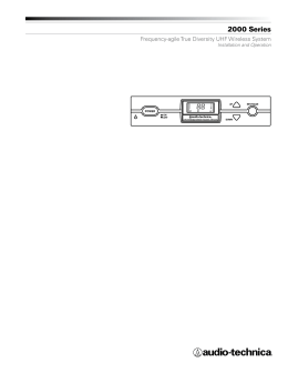
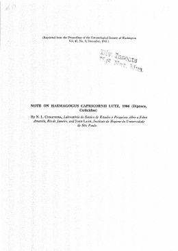
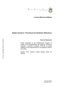
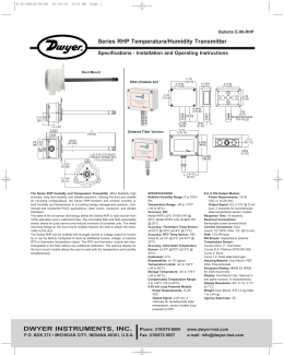
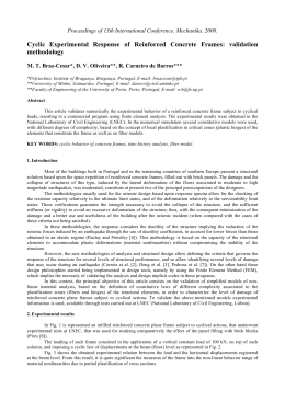
D811527 ver.04 18-01-10
I
GB
SISTEMA RICEZIONE RADIOCOMANDI ROLLING-CODE, CODICI E TESSERE
RECEPTION SYSTEM FOR ROLLING-CODE RADIO TRANSMITTERS, CODES AND CARDS
8
027908 3 0 1 3 8 3
SYSTÈME DE RÉCEPTION RADIOCOMMANDES ROLLING-CODE, CODES ET BADGES
EMPFANGSSYSTEM FÜR FERNBEDIENUNGEN, ROLLCODE, CODES UND ERFASSUNGSKARTEN
SISTEMA DE RECEPCION DE RADIOMANDOS ROLLING-CODE, CODIGOS Y TARJETAS
SISTEMA DE RECEPÇÃO DE RADIOCOMANDOS ROLLING-CODE, CÓDIGOS E CARTÕES
CLONIX 4 RTE
ISTRUZIONI D’USO E DI INSTALLAZIONE
INSTALLATION AND USER’S MANUAL
INSTRUCTIONS D’UTILISATION ET D’INSTALLATION
INSTALLATIONS-UND GEBRAUCHSANLEITUNG
INSTRUCCIONES DE USO Y DE INSTALACION
INSTRUÇÕES DE USO E DE INSTALAÇÃO
Via Lago di Vico, 44
36015 Schio (VI)
Tel.naz. 0445 696511
Tel.int. +39 0445 696533
Fax 0445 696522
Internet: www.bft.it
E-mail: [email protected]
D811527_04
INSTALLATION MANUAL
Thank you for buying this product, our company is sure
that you will be more than satisfied with the product’s
performance. The product is supplied with a “Warnings”
leaflet and an “Instruction booklet”. These should both
be read carefully as they provide important information
about safety, installation, operation and maintenance.
This product complies with the recognised technical
standards and safety regulations. We declare that this
product is in conformity with the following European
Directives: 2004/108/EEC and 2006/95/EEC (and
subsequent amendments).
GENERAL SAFETY
WARNING! An incorrect installation or improper
use of the product can cause damage to persons,
animals or things.
• The “Warnings” leaflet and “Instruction booklet”
supplied with this product should be read carefully
as they provide important information about safety,
installation, use and maintenance.
• Scrap packing materials (plastic, cardboard, polystyrene etc) according to the provisions set out by
current standards. Keep nylon or polystyrene bags
out of children’s reach.
• Keep the instructions together with the technical
brochure for future reference.
• This product was exclusively designed and
manufactured for the use specified in the present
documentation. Any other use not specified in this
documentation could damage the product and be
dangerous.
• The Company declines all responsibility for any
consequences resulting from improper use of the
product, or use which is different from that expected
and specified in the present documentation.
• Do not install the product in explosive atmosphere.
• The construction components of this product must
comply with the following European Directives:It
complies with the 2004/108/EEC, 1999/5/CEE,
European Directive and subsequent amendments.
As for all non-EEC countries, the above-mentioned
standards as well as the current national standards
should be respected in order to achieve a good
safety level.
• The Company declines all responsibility for any
consequences resulting from failure to observe
Good Technical Practice when constructing closing
structures (door, gates etc.), as well as from any
deformation which might occur during use.
• The installation must comply with the provisions set
out by the following European Directives:It complies
with the 2004/108/EEC, 1999/5/CEE, European
Directive and subsequent amendments.
• Disconnect the electrical power supply before carrying out any work on the installation. Also disconnect
any buffer batteries, if fitted.
• Fit an omnipolar or magnetothermal switch on the
•
•
•
•
•
•
•
•
•
•
•
•
•
ENGLISH
mains power supply, having a contact opening
distance equal to or greater than 3,5 mm.
Check that a differential switch with a 0.03A threshold is fitted just before the power supply mains.
Check that earthing is carried out correctly: connect all
metal parts for closure (doors, gates etc.) and all system
components provided with an earth terminal.
Fit all the safety devices (photocells, electric edges
etc.) which are needed to protect the area from
any danger caused by squashing, conveying and
shearing.
Position at least one luminous signal indication device
(blinker) where it can be easily seen, and fix a Warning
sign to the structure.
The Company declines all responsibility with respect
to the automation safety and correct operation when
other manufacturers’ components are used.
Only use original parts for any maintenance or
repair operation.
Do not modify the automation components, unless
explicitly authorised by the company.
Instruct the product user about the control systems
provided and the manual opening operation in case
of emergency.
Do not allow persons or children to remain in the
automation operation area.
Keep radio control or other control devices out of
children’s reach, in order to avoid unintentional
automation activation.
The user must avoid any attempt to carry out work
or repair on the automation system, and always
request the assistance of qualified personnel.
Anything which is not expressly provided for in the
present instructions, is not allowed.
Installation must be carried out using the safety
devices and controls prescribed by the EN 12978
Standard.
1) GENERAL OUTLINE
The CLONIX 4 RTE receiver is characterised by:
- outputs with relay contacts insulated (1 output
with changeover contact, 3 outputs with N.O.
contacts).
- programming of outputs as monostable, bistable,
timed.
- absolute safety thanks to coding with variable
code (rolling code).
- radio programming for transmitters.
- presetting for the reception of transponder cards
and codes from the numerical keypad (wiegand
26 standard).
- transmitter cloning.
Cloning a transmitter means creating a transmitter
which can be included automatically within the list
of the transmitters memorised in the receiver, either
as an addition or as a replacement of a particular
transmitter.
CLONIX 4 RTE - 7
INSTALLATION MANUAL
D811527_04
ENGLISH
Therefore it will be possible to remotely program a
large number of additional transmitters, or for example,
replacement transmitters for those which have been
lost, without making changes directly to the receiver.
Cloning by replacement is used to create a new
transmitter which takes the place of the one previously memorised in the receiver; in this way the lost
transmitter is removed from the memory and will no
longer be usable
Using clones when there is more than one receiver
(as in the case of communal buildings), and especially
when a distinction is to be made between clones to be
added to or replaced in individual or collective receivers, could turn out to be rather difficult. The CLONIX 4
RTE receiver cloning system for communal buildings
makes it particularly easy to solve the problem of clone
storage for up to 250 individual receivers.
on the transmitter, and the DL1 led will stay on
permanently.
Note: Hidden key P1 looks different depending on
the transmitter model.
4) Press the transmitter key to be memorised, and
the DL1 led will start blinking again.
5) To memorise another transmitter, repeat steps 3)
and 4).
6) To come out of the memorisation mode, wait until
the led is completely switched off.
IMPORTANT NOTE: ATTACH THE ADHESIVE KEY
LABEL TO THE FIRST MEMORISED TRANSMITTER (MASTER).
In the case of manual programming, the first transmitter assigns the key code to the receiver; this code is
necessary in order to carry out subsequent cloning of
the radio transmitters.
2) TECHNICAL SPECIFICATIONS
Frequency...............................................:433.92MHz
Working temperature..............................:-20 / +55°C
Coded by means of...............:Rolling-code algorithm
No. combinations........................................:4 milliard
Power supply.................................:230V ±10% 50Hz
Antenna impedance..........................:50Ohm (RG58)
Relay contact ............................................:4 x 16A
Max no. radio transmitters to be memorised.:..........128
Max absorption on 12V..................................:100mA
4.2) Transmitter storage via radio in self-learning
mode
This mode is used to memorise a transmitter without
having to access the receiver.
The first transmitter is to be memorised in manual
mode.
a) Press hidden key P1 on the transmitter already memorised.
b) Press key T on the transmitter already memorised,
which is also to be attributed to the new transmitter.
c) Within 10 sec., press key P1 on the new transmitter
to be memorised.
d) Press key T to be attributed to the new transmitter.
e) To memorise another transmitter, repeat the procedure from step (c) within a maximum time of 10
seconds, otherwise the receiver exits the programming mode.
f) To copy another key, repeat from step (a), having
waited for the receiver to exit the programming
mode (or after disconnecting the receiver from the
power supply).
2.1) CONNECTIONS See Fig.6
3) ANTENNA INSTALLATION
Use an antenna tuned to 433MHz.
For Antenna-Receiver connection, use RG8 coaxial
cable.
The presence of metallic masses next to the antenna can interfere with radio reception. In case of
insufficient transmitter range, move the antenna
to a more suitable position.
4) PROGRAMMING
The TRANSMITTERS can be memorised in manual
mode or by means of the universal palmtop Programmer,
which allows installations to be carried out in “common
receivers” mode and managed by means of the EEdbase
software for complete installation database.
4.1) Manual memorisation of transmitters, see fig.1-2
In the case of standard installations, which do not require
advanced functions, the transmitters can be memorised
manually, making reference to Fig.2.
1) If you wish the transmitter to activate output 1, press
the SW1 button, whereas if you wish the transmitter
to activate output 2, press the SW2 button.
2) If you wish to use functions other than those for
monostable activation, make reference to Fig.1
and 2.
3) When the DL1 led blinks, press hidden key P1
8 - CLONIX 4 RTE
5) RADIO-TRANSMITTER CLONING
Rolling-code cloning.
Make reference to the instructions for the universal
palmtop programmer and to the CLONIX programming guide.
6) ADVANCED PROGRAMMING: COLLECTIVE
RECEIVERS
Make reference to the instructions for the universal
palmtop programmer and to the CLONIX programming guide.
7) MANUAL PROGRAMMING OF CARDS AND
CODES FROM THE KEYPAD (WIEGAND 26 standard),
see Fig. 3-4
D811527_04
INSTALLATION MANUAL
ENGLISH
8) ACTIVATION TIME SETTING FOR TIMED OUTPUT: See Fig.5.
9) MAINTENANCE
The maintenance of the system should only be
carried out by qualified personnel regularly.
10) DISPOSAL
ATTENTION: disposal should only be carried out
by qualified personnel.
Materials must be disposed of in conformity with the
current regulations.
In case of disposal, the system components do not entail
any particular risks or danger. In case of recovered
materials, these should be sorted out by type (electrical
components, copper, aluminium, plastic etc.).
For battery disposal, refer to the current regulations.
The descriptions and illustrations contained in
the present manual are not binding. The Company
reserves the right to make any alterations deemed
appropriate for the technical, manufacturing and
commercial improvement of the product, while
leaving its essential features unchanged, at any
time and without undertaking to update the present publication.
CLONIX 4 RTE - 9
A
B
C
Il relè dell'uscita abbinata, resta attratto finché riceve il comando via radio dal telecomando.
The associated output relay remains picked up as long as it is receiving the command wirelessly from the
remote control.
Le relais de la sortie associée reste excité tant qu'il reçoit la commande via radio de la télécommande.
Das Relais des zugeordneten Ausgangs bleibt solange angezogen, wie der Befehl er Fernbedienung über
Funk empfangen wird.
El relé de la salida asociada permanece excitado mientras recibe el mando vía radio del mando a distancia.
O relé da saída associada, fica accionado enquanto recebe o comando via rádio do telecomando.
A
B
Il relè dell’uscita abbinata, cambia stato ad ogni pressione del tasto della trasmittente.
The relay of the coupled output changes status each time the transmitter key is pressed.
Le relais de la sortie associée change d’état à chaque pression de la touche de l’émetteur.
Das Relais des zugeordneten Ausgangs ändert seinen Zustand bei jeder Betätigung der Sendertaste.
El relé de la salida asociada cambia de estado cada vez que se pulsa la tecla del transmisor.
O relé da saída associada, muda de estado a cada pressão da tecla do transmissor.
C
T
T
FIG.2
SW1
SW2
SW3
SW4
---->
---->
---->
---->
CH1
CH2
CH3
CH4
Ad ogni pressione del tasto della trasmittente, il relè dell’uscita resta attratto per il tempo impostato tramite
dip-switch (Fig.5). Pressioni del tasto durante il ciclo di conteggio reinizializzano il conteggio stesso.
Each time the transmitter key is pressed, the output relay remains picked up for the time set by means
of the dip switch (Fig.5). When the key is pressed during the count cycle, the actual count is restarted.
À chaque pression de la touche de l’émetteur, le relais de sortie reste excité pour le temps programmé par
l’interrupteur DIP (Fig.5). Les pressions de la touche pendant le cycle de comptage réinitialisent le comptage lui-même.
Bei jeder Betätigung der Sendertaste bleibt das Ausgangsrelais für die Dauer angezogen, die per Dip-Switch
eingestellt wird (Abb. 5). Tastenbetätigungen während des Herunterzählens führen dazu, dass die Zeit erneut
zu laufen beginnt.
Cada vez que se pulsa la tecla del transmisor, el relé de la salida permanece excitado durante el tiempo configurado
mediante dip-switch (Fig. 5). Si la tecla se presiona durante el ciclo de cálculo, se reinicializa dicho cálculo.
A cada pressão da tecla do transmissor, o relé da saída fica accionado pelo tempo definido por meio do
dip-switch (Fig.5). Pressões da tecla durante o ciclo de contagem reinicializam a própria contagem.
1
A
1
1
15 s
2x
EXIT
1
A
T1-->CH1
T2-->CH2
T3-->CH3
T4-->CH4
1
15 s
3x
EXIT
1
B
1
4x
15 s
EXIT
1
C
15 s
5x
EXIT
1
N.D.
N.D.
6x
1
Cancellazione dell’intera memoria della ricevente.
Cancellation of the entire receiver memory.
Annulation de toute la mémoire du récepteur.
Löschen des gesamten Empfängerspeichers.
Cancelación de toda la memoria del receptor.
Cancelamento de toda a memória do receptor.
EXIT
22 - CLONIX 4 RTE
SW1
SW2
10 sec.
EXIT
D811527_04
INSERIMENTO RADIOCOMANDI /ENTRY OF RADIO TRANSMITTERS /INSERTION RADIOCOMMANDES /
EINFÜGEN VON FERNBEDIENUNGEN / INSERCION DE RADIOMANDOS /INTRODUÇÃO DE RADIOCOMANDOS.
FIG.1
D811527_04
FIG.3
INSERIMENTO CODICI O TESSERE / ENTRY OF CODES OR CARDS / INSERTION CODES OU BADGES / EINFÜGEN VON
CODES ODER ERFASSUNGSKARTEN / INSERCION DE CODIGOS O TARJETAS / INTRODUÇÃO DE CÓDIGOS OU CARTÕES
A
B
Il relè dell'uscita abbinata, resta attratto per circa 1 secondo.
The relay of the coupled output remains picked up for about 1 second.
Le relais de la sortie associée reste excité pendant environ 1 seconde.
Das Relais des zugeordneten Ausgangs bleibt etwa 1 Sekunde lang angezogen.
El relé de la salida asociada permanece excitado durante aproximadamente 1 segundo.
O relé da saída associada, fica accionado por cerca de 1 segundo.
A
1s
1s
1s
B
C
T
T
FIG.4
FIG.4
SW1
SW2
SW3
SW4
---->
---->
---->
---->
CH1
CH2
CH3
CH4
Il relè dell’uscita abbinata, cambia stato ad ogni riconoscimento della tessera o del codice memorizzato.
The relay of the coupled output changes status each time the card or the memorised code is
recognised.
Le relais de la sortie associée change d’état à chaque reconnaissance du badge ou du code mémorisé.
Das Relais des zugeordneten Ausgangs ändert bei jeder Erkennung der Erfassungskarte oder des
gespeicherten Codes seinen Zustand.
El relé de la salida asociada cambia de estado con cada reconocimiento de la tarjeta o del código
memorizado.
O relé da saída associada, muda de estado a cada reconhecimento do cartão ou do código memorizado.
Ad ogni riconoscimento della tessera o del codice memorizzato, il relè dell’uscita resta attratto per il tempo
impostato tramite dip-switch. Riconoscimenti della tessera o del codice memorizzato durante il ciclo di
conteggio reinizializzano il conteggio stesso.
Each time the card or the memorised code is recognised, the output relay remains picked up for the
time set by means of the dip switch. When the card or the memorised code is recognised during the
count cycle, the actual count is restarted.
À chaque reconnaissance du badge ou du code mémorisé, le relais de sortie reste excité pour le temps
programmé par l’interrupteur DIP. Les reconnaissances du badge ou du code mémorisé pendant le cycle
de comptage réinitialisent le comptage lui-même.
Bei jeder Erkennung der Erfassungskarte oder des gespeicherten Codes bleibt das Ausgangsrelais für
die Dauer angezogen, die per Dip-Switch vorgegeben worden ist. Wird während des Herunterzählens
eine Erfassungskarte oder ein gespeicherter Code erkannt, beginnt die Zeit erneut zu laufen.
Con cada reconocimiento de la tarjeta o del código memorizado, el relé de la salida permanece excitado
durante el tiempo configurado mediante dip-switch. Reconocimientos de la tarjeta o del código
memorizado durante el ciclo de cálculo reinicializan dicho cálculo.
A cada reconhecimento do cartão ou do código memorizado, o relé da saída fica accionado pelo
tempo definido por meio do dip-switch. Reconhecimento do cartão ou do código memorizado
durante o ciclo de contagem reinicializam a própria contagem.
C
1
A
1
1s
1
2x
15 s
EXIT
1
N.D.
1
N.D.
3x
1
B
1
1s
4x
EXIT
1
C
1s
5x
15 s
EXIT
1s
1
Cancellazione di un codice singolo
Cancellation of a single code
Annulation d’un code simple
Annullierung eines einzelnen Codes
Cancelación de un código individual
Cancelamento de um único código
15 s
EXIT
6x
Cancellazione dell’intera memoria della ricevente.
Cancellation of the entire receiver memory.
Annulation de toute la mémoire du récepteur.
Löschen des gesamten Empfängerspeichers.
Cancelación de toda la memoria del receptor.
Cancelamento de toda a memória do receptor.
15 s
1
10 sec.
SW1
SW2
EXIT
EXIT
CLONIX 4 RTE - 23
FIG.5
2
3
OFF
OFF
OFF
OFF OFF
OFF
ON
ON
OFF
OFF
ON
ON
OFF
ON
4
OFF
ON
5
180s
15min
ON
1h
6
OFF
ON
OFF
180s
OFF
OFF
15min
ON
ON
ON
ON
ON
OFF
ON
ON
ON
180s
ON
12h
ON
OFF
30s
1h
CH2
OFF
OFF
CH4
OFF
ON
12h
10
OFF
OFF
30min
ON
OFF
OFF
9
6min
OFF
OFF
ON
OFF
30s
60s
ON
ON
ON
CH1
ON
30s
ON
60s
ON
7
6min
ON
OFF
1h
ON
180s
ON
30min
ON
OFF
ON
2h
CH3
OFF
OFF
30min
8
ON
OFF
30s
6min
FIG.6
LED presenza alimentazione,
Power supply on LED,
LED présence alimentation,
LED Spannungsanzeige,
LED de presencia de alimentación,
LED presença alimentação
LED programmazione,
Programming LED,
LED programmation,
LED Programmierung,
LED de programación,
LED programação
WIEGAND 26
1
2
3
4
5
6
+ 12V
D1
D0
GND
LED A
LED B
1 2 3 4 5 6 7 8 9 10
SW1
CH4
4
5
6
COM
NO
COM
NO
Max 16A
CH3
COM
NO
NC
COM
NO
230V 50Hz
CH2
3
CH1
2
N
SW3
SW4
1
L
SW2
Max 16A
Max 16A
Max 16A
Connettore WIEGAND 26 per lettore tessere e tastierino numerico,
WIEGAND 26 connector for card reader and numerical keypad,
Connecteur WIEGAND 26 pour lecteur de badges et clavier numérique,
Steckverbinder WIEGAND 26 für Kartenleser und Ziffernblock,
Conector WIEGAND 26 para lector de tarjetas y teclado numérico,
Conector WIEGAND 26 para leitor de cartões e teclado numérico.
max 100 mA!
DIP SWITCH
Connettore programmatore palmare,
Palmtop programmer connector,
Connecteur programmateur de poche,
Steckverbinder Handprogrammiergerät,
Conector para programador de bolsillo,
Conector programador palmar.
1
OFF OFF
1 2 3 4 5 6 7 8 9 10
CLONIX 4 RTE
Calza,
Braid,
Gaine
Geflecht,
Trenza,
Fio trançado.
Antenna,
Antenna,
Antenne,
Antenne,
Antena,
Antena.
Baixar