AEROPORTO FRANCISCO SÁ CARNEIRO [PORTO]
!
"# $
"
%
&
'
( )* &
+
,
.
/ 0* * ( .0* #
-
!
!"
#
#
!
%
$%
&''"
#
(
&''"
)*
)+
#
,
&''0
!
.'/
)*/
-
,
1
,
!
(
2
3
#
$
,
!
,
,
(
3
1
*
#
4
5'
2
,
7
6
,
(
1
8
#
!
1
9
9
9
:
#
1
9
1
!
(
%
;
<
=
!
?
=
>
@
,
A
(
!
9
3
#
#
#
A
3
=
=
,
>
6
(
!
>
1
A
,
2
,
9
3
9
(
2
#
1 ,
6
B
,
=
>
1
=
9
-
#
,
1
(
%
#
1
9
=
6
A
(
B
3
1
>-
9
-
2
;
#
19
4 1
6
(
B
1
=
1
=
1 ,
1
=
=
1
, # (
6
;
B
19
!
>-
(
!
!
"
#
$
%
&
'
! '
#
(
!
)
&
*
-
+
%
%
%& ,
*
!
"
,
0
.
.
!"
4
2
!
#
!1
1
#
.
,
-
!
/
"
2
,
,
.
-
-
+
%& ,
3
3
4
&
!
'
%
56
78
%
&
&"
&"
&
&
!
9 '
#
!
#
"
:
&
!
% !
!
!
2 #
%
*
&
&
'
!
%
&
*
"
('
;
#
!
"
!
,
!
!
, <!
, 67
%
"
, <9 8
*
"
#
;
'
!
!
&
.
&
#
< =
#
*
1
7
; !
!
;
#
#
,
)
!"
,
$
&
!"
2
6>>>
"
(
*
$
(
!
&
!
@
)
#
/
1
"
#
"
!
#
)
@
#
!
/
B
/
#
"
' A
#
6>>?
1
&
"
!
"
#
#
#
: ;
1
9
/
#C
%& ,
#
&
+
&
;
9
!
#
!
!
#
"
,
"
1
/
"
"
"
!
;
#
#
"
1
2;
"
&
/
"
#
!
"
!
"
;
;
#
&
#
,
: ;
1
/
"
;
"
;
;
!
#
#
1
,
1
&
#
%
"
:
D;
"
E
;
#
" (
#
#
!
E
/
#
-
-
1
/
1
#
&
#
#
&
"
1
#
A
/
&
1
#C
E
A
#C
1
#
' A
#
A
'
;
#
#
* $
(
6>>>!
#
F%
, G!
9
" #
! ; ,
H
6>>6
#
"
6>>8! %
#
!
, " "
,
#
6>>7
*
&
:
*
#
8
!
"
!"
1
##
%
!
"
6>><!
#
#
)
#
!
F G
I JKE6>>>!
$
-
$
&
F
G
+
)
)
!
%& ,
!
F %, 6>>>G
#
"
" A
;
#
!
'
#
;
!
3
3
"
;
3
(
(
(
3 ;
3
(
(
3"
!
3
3
"
$
&!
!
#
!
"
!
#
1
6>>7G
F$
*
!"
!
,
2
;
,
!
)
6>>>!
#%
#
"
#
#$
'
#C
:
!
#
)
%,
)
#
#
*
A
,
"
"
2
;
,
!
)
)
"
!
"
#
#
!
&
"
#
)
!
$
$
&
4 &
$
A
)
I JKE6>>>!
8
F$ 2 JKE6>>>G!
#C
$
2
I <K5E6>>?!
L
F$ 2 <K5E6>>?G
:
" #
I 6E6>>J
J
H
!
9
#
2
$
$
#
"
#
:
;"
)
$ 2 JKE6>>>!
!
#
!
!
'
!
)
;
/
'
1
G ,
5! ;
#
)
6<>>
'
1
<>
1 )
"
(
!
#
F
MN <?>>
&
!
"
/,
1
;
;
,
G
#
' G/
;
/4
)
$#
4
#
/
6<
#
# !
)
!
'
;
'
#
#
!
!
'
4
<8
" #
;
'
! O
'
#
)
)&
# !
;
'
'
#
'
F
" #
#
;
&
$$
"
"
9
!
#
#
&
#
"
A
!
!
#
!
# !
' G
%
#
1
#
: " A
/
O
3
:
D;
F&
%
"
: ;
+
+
G3
3
3
: ; 3
1
3
%(
*
1
(
D
!
&
(
4
(
3
,
#
$%
#
F
&
"
G! "
$'
#
"
;
$(
!
!
!
;
"
"
1
"
&
$)
F
!
!
$
9
&
#
"
#
!
#
&
!
!
#
"
!
)
!
(
#
#
!
$*
#
,
"
"
!
&
"
#
#C /
&
)
#
* )
H
#
"
#
1 )
,
)
)
!
&
$
#
)
1 )
,
G
#
;
$
#
C
!
;
#
,
!
"
!
#
"
"
! "
!
";
#
#
"
1 )
!
,
#
1
-
#
#
#
#
'
;
-
,
'
#
!
#
#
&
F
"
G
#
#
"
-
#
-
,
#
!
#
,
C
2
;
"
,
C
4
1
$"
:
" A
"
#
4
,
#
)
1
!
!
!
$
"
!
!
1
#
;
:
$ +
#
'
#
#
!
"
!
&
/
;
;
3
3
3
;
"
3
!"
3
3
(
(
(
(
3
3
"
#
#C
#
$
)
#
F: , 1 G!
:
'
$
&
$
"
#
1
(
F$
'
!
:
D
$
G
$
#
"
:
,
"
#C
,
F$
!
$
"
)
G
6>>>!
I <76EK5
!
&
&
,
#
#
9 :
I 5JE6>>>!
,
-
!
1
"
F$
1
!
#
&
#
#
!
I K6E78E,
I 5KE7>KE, !
,
G
#
A
1
$ #
!
F1 * G
*
%
!
,
$
1
"
!
)
1
&
8
)
)
'
#C
!
)
!
!
P %, 6>>>Q
,
2 ;
9 1
+
)&
!
#
,
&
!
!
$
#C
%& ,
+
+
$
1
&
/
/
+
$
J - 1 RE
&
1
:
#
)
A
+
!
$
!
" #
#
'
#
*
A
&
!
!
#
"
&
#C
)&
!
'
#C
+
:
+
$
Q << < - 1 R E
#
3
#
$
+
:
+
P-
!
&
P@
#
+
Q S <6E<? - 1 R E
#
$
!
" #
$
%
&#
'
#
*
(
)
#
$
+
,
-. /
&' $
/
0
& (
# ,
/
1
$
2
&
#
/#
/
*
4
/
/
$
/
&
/
!
&
;
&
'
!
9
6
#
/,
/
3
#
&
3
$
)
#
!& /
) /
$
/
*!
788-/ 1.
:#
/
'
3
&
5
9
/
<8
/
#
*
(
-
4
; *
4
*
'
)
)
78
!
!
/#
=/>
/
$
&
<8
)
?
/
& (
$
& (
@
/ #
!
$
0
"
/
!
A
$
/
4
/*
4
%/
9
:
/#
&
)
" /
BC1. D
#
/
%
/
*!
/
(
&
'
/
$
#
$
/
(/
/
%
/
/
/
*
#
&
0
!
!
&
/!
!
,
0
#
&
$
#
*
888 *
$
/
!
$
(
4
& (
/
/
& )
/
6 *$
0
/
! &
$
E=.
&
B-8. D/ F G
!
!
B>. D
H
/
#
B1. D$
#
6
&
/
&
#
'
F
$
=$=$7
4
!
/ & # (
&
0
/
C
$
#
/#
4
3
/
4
$
I
# /
788=/
!
&
*!
/
/
,
&
78. / & )
5
&
/
#
&
/
)
'
&
'
*,
#
!
=
7881
#
$
*
/
78 8 1 / $ $ 1
4
78 8$
7
&
/
/
/
"
&
&
$
I *
!
&
/ &
& /
(
!#
(
$
/
'
#
& (
/
&
/
/
*
/
/
$+
&
FH
#
%
! /
K #
!
(
/
#
4
*
!
/
!
#
/ &
&
' $
$ +
)
/
$
3
$
/
&"
:
/
#
/
*
&
/
0
*,
*
=$E/
4
2
0
!
$ J+
$
"
&
#
$
*
I
'
*
/
$
*,
!
!
(
/
'
&
$
#
#
$
&
,
#
!
#
4
*,
* /
#
#
#
788-L788>
&
$
/
& "' /
#
$
=
$
7$
=$
=$
=$ $
=$ $7
=$ $=
=$ $C
=$7
=$7$
=$7$7
=$7$=
=$7$C
=$7$1
=$7$=$=
=$=$
=$=$7
=$C
=$C$
=$C$7
=$1
=$=$E
=$>
C
C$
C$7
C$=
C$C
C$1
1
-
F
N
F
I
M M M M M M M M M M M M M M M M M M M M M M M M M M M $$$
/O
/9
*
D M M M M M M M M M M M M M $$$$
%
(
M M M M M M M M M M M M M M M M M M M M M M M $$$
,
M M M M M M M M M M M M M M M M M M M M M M M M M M M M M M $$
I
)
M M M M M M M M M M M M M M M M M M M M M M M M M M M M M M $$$
;
M M M M M M M M M M M M M M M M M M M M M M M M M M M M M M M M $$$$
%
)
M M M M M M M M M M M M M M M M M M M M M M M M M M M M M $$$$
I )
M M M M M M M M M M M M M M M M M M M M M M M M M M M M M M $$$$
M M M M M M M M M M M M M M M M M M M M M M M M M $$$
% &
M M M M M M M M M M M M M M M M M M M M M M M M M M M M $$$
M M M M M M M M M M M M M M M M M M M M M M M M M M $$$$
F
M M M M M M M M M M M M M M M M M M M M M M M $$$
F
M M M M M M M M M M M M M M M M M M M M M M M M $$$
F
M M M M M M M M M M M M M M M M M M M M M M M M $$$$
*
M M M M M M M M M M M M M M M M M M M M M M M M M M M M M $$$$
&
M M M M M M M M M M M M M M M M M M M M M M M M M M $$$$
I
M M M M M M M M M M M M M M M M M M M M M $$
M M M M M M M M M M M M M M M M M M M M M M M M M M M $$
(
F
M M M M M M M M M M M M M M M M M M M M M M $$$
% &
M M M M M M M M M M M M M M M M M M M M M M M M M M M M $$$$
%
(
M M M M M M M M M M M M M M M M M M M M M M M M M $
F
M M M M M M M M M M M M M M M M M M M M M M M M M M M M $$
M M M M M M M M M M M M M M M M M M M M M M M M M M M M M M M M
FH %
M M M M M M M M M M M M M M M M M M M $
2
M M M M M M M M M M M M M M M M M M M M M M M M M M M
I
!
M M M M M M M M M M M M M M M M M M M M M M M M M $
O
'
F
M M M M M M M M M M M M M M M M M M M M M M M $$
M M M M M M M M M M M M M M M M M M M M M M M M M M M M M
M M M M M M M M M M M M M M M M M M M M M M M M M M M M M M M M M
*,
I
% &
M M M M M M M M M M M M M M M M M M M M M
M M M M M M M M M M M M M M M M M M M M M M M M M M M M M M M M M $
4
788- 788> M M M M M M M M M M M M M M M M M M M M $$
"
M M M M M M M M M M M M M M M M M M M M M M M M M $
B
'
C
>
>
>
<
<
8
>
7C
71
7<
==
=C
=C
=C8
C8
C7
C=
C1
CE
CE
CE
C>
C>
C>
C<
18
1=
11
C
O
O
O
O
O
O
O
O
O
O
O
O
O
O
O
O
O
O
O
O
O
O
O
O
O
O
O
O
O
O
O
O
O
O
O
O
O
O
O
O
$ =$
$ =$7
$ =$=
$ =$C
$ =$1
$ =$$ =$E
$ =$>
$ =$<
$ =$ 8
$ =$
$ =$ 7
$ =$ =
$ =$ C
$ =$ 1
$ =$ $ =$ E
$ =$ >
$ =$ <
$ =$78
$ =$7
$ =$77
$ =$7=
$ =$7C
$ =$71
$ =$7$ =$7E
$ =$7>
$ =$7<
$ =$=8
$ =$=
$ =$=7
$ =$==
$ =$=C
$ =$=1
$ =$=$ =$=E
$ C$
$ C$7
$ C$=
P@
P@
P
P
P
P
P
P
P
P
P
P
P
P
P
P
P
P
P
P
P
P )
P )
P )
P )
P )
P )
P% &
P% &
P% &
P
P
P
P
P
P
P
P%
P
P% &
Q
Q
5
5
P
P
1
1
"
&
& F
&
P
%
7881
% &
%
P
P
P
P
P
P
P
P
P
A
P
&
& F
&
%
4
4
&
& F
&
%
;
4
P 788CL7881
7881
F
P 7881
% &
% &
O
% &
P 788CL7881
7881
% &
P 7887L788% &
R
& (
=8/ -8/ <8
78
=8/ -8 <8
$P
F
=8/ -8 <8
$P
@
=8/ -8 <8
$P
=8/ -8 <8
$P
; *
<8
1
B1
7881 788C P
B1
7881 788C P
B8
7881 788C P
2
2
A
A
B7881D
7881 P
PA "
7881 P
PA "
PI
5
A "
A
!
P
A
P
@
!
$D
$D
D
1
!
9
9
9
9
9
9
9
9
9
9
9
9
9
9
9
9
9
9
9
9
9
9
9
9
9
9
9
9
9
9
9
9
=$
=$7
=$=
=$C
=$1
=$=$E
=$>
=$<
=$ 8
=$
=$ 7
=$ =
=$ C
=$ 1
=$ =$ E
=$ >
=$ <
=$78
=$7
=$77
=$7=
=$7C
=$71
=$7=$7E
=$7>
=$7<
=$=8
=$=
C$
P
P
P
P
P
P
P
P
P
P
P
P
P
P
P
P
P
P
P
P
P%
P
P
P
P
P
P
P% *
P2
PO
P
P *,
R
1
P )
=8/ -8/ <8
78
& (
!
,
&
"
"
"
"
"
"
"
"
"
*
4
&
*
& # (
&
#
0
A
"
L 3
P@
"
&
4
2
0
0
R
A "
@
Q
0
!
/
&
O
FH
%
&
-
"
I0
I
@
Q%
20
T
T FF
I
A%
F%I
OF
%
I
S
#
G0
%
!
)
0
I
@
(
Q
%
2
!
O
0
T "
T F &F
I
!
A
%
F
%!
F
%
"
I
O%
;F
0
%
;
;O
!
O
;
I
%
FG
0
%
; 6
;
O
I
%
/
I
&
&
Q
2OOF
2O
2 I
FIA I2
%2
%
TI
T 0 U F0 2
@O
/
2
2
F
%!
%
T
T
@
%
4
Q
O O
F
O #
G
&
4
2
/
*
A
&
4
2
,
4
I
5*
I
4
U
2
0
O
E
$
%&' %
$
*
$
%(
)
%
%
+
%
& (
5
,
'
788=/
0
A " / EC/E.
/ - /1.
QL
QL
!
&
:
&
#
I
!
)
#
T
T
I
I
W
$
'
!
(
I
/
" V
#
/
(
:
T
$
+
788-/
V
&
&
7/8.
/1.
/8.
8/1.
8/8.
8/1.
788
7887
788=
788C
7881
788-
/8.
/1.
, $- @
Q
B
I
$+
5
1
Q
D
/
A
#
" /
V
>/8.
-/8.
C/8.
7/8.
8/8.
788
7887
788=
, $- @
Q
B
788C
5
1
7881
A
"
A ID
>
$
, %(
0 /F
!
)
#
5*
/
*
I
*
$
/
'
"
$
*
'
!
#
/
%
% &
!
%
0
%
0
5*
$;$ 87L<8
&
/
7
/
$
'
V
PO
0 W
(
/
I
P&
0 /F /
)
)
!
W
P &
0 /F /
W
%
0
!
*
&
5*
4
& / *
&
$;$ C8CL<>
/
:
0
"
V
P&
/
&
T
#
$
0 /F W
188$888
"
/
L
/
4
&
#
#
4
!
/
" /
/ *
,
#
#
&
&
$
$
$
0
(+ , %
5
&
/
*
;
*
"#
$
4
/
*
!
&
4
$
/
*
/
)
/
*
!
'
4
<
B
#
'
D/
$
QE>E/
"
Q
#
#
$
'
&
/
&
5
"
T FF/
H O/
)
.
(+ , %
!
!
& (
#
*
!
/ 2O
/
/ $
* #
X 7887L=8L I/
'
I
/
:
/#
$
6
4
T
*
I
/
6 *
"
$I
"
/
4
$
*
#
*
' /
/
*
L
*
#
/
$
)
!/
;$ 7<=L788=
*!
&'
<
0
&
/
18$888
&
* $
*
&
/
&
$
=
7881/ <E$C.
# /
/
#
&
I
#
"
/
' /
@
$
&
#
5
$ =
-
/
88. $
8
$
/
%
0
$
1 ,
/
0
%(
&
"
0
/!
$
'
'
*
@
&
&
5
IT 2 788C
?
0
/
/
$
&
&
3
$
1$888
2004
2005
C$888
, $-$
P
&
=$888
7$888
$888
8
? 0
OI@
2
*
Q2
?T 0
?T ;
A
/
FI%
T%
0 @
IY
*! /
$
E$888
2004
-$888
, $-.
P
& F
2005
1$888
C$888
=$888
7$888
$888
8
FIA
%I2
9T
9T
FIZ
F Q
0
#
/
&
/
>U 88$ [
#
8>U 88
/
&
/
"
"
*
/
&
8U 88
/
-U 88
/
$
/
'
'
/
C888
Mov./hora
=888
, $-2
&
7888
7881
888
8
7
=
C
1
-
E
>
<
8
7
=
C
1
-
E
>
< 78 7
77 7= 7C
&
&
& )
J 6
#
K
$
0
/
/
*
788C
,
788-
#
#
8.
&
$
1888
I&
LCC
Cargo
Charter
FSC-Reg.
IT 2 788C
C888
=888
7888
, $-3
P
%
% &
8C
81
08C
081
81
8C
F81
F8C
8C
81
?81
?8C
?81
?8C
8C
81
8C
81
8C
81
O81
O8C
?81
8
?8C
888
P 788CL7881
7
/
0 442 -
0
1 , 5
6 0
&
L
/ ->/ -E
"
&
=1 &
!
$
!
%
%&'
&
-=
/ 7=L "
=L?
/
$
->.
C/C
C=
&
$
E/
$
6
2
&
6 *
/
/
G
&
,
18
&
F
/ &
$
#
&
U *\
I
#
/
&
*!
"
4
$
I
/
/#
/#
$
'
'
2E 1,7%
U > 1,8%
E=>
2,9%
E17
4,0%
=7
4,1%
11,1%
88
17,4%
I2C
18,1%
= <
20,5%
=78
8/8.
8/8.
, $-7
%
78/8.
7881
=
#
&
&
&
F
9
# (
#
*
#
2,5%
7
11,4%
6
70,7%
5
4,4%
6,2%
4
4,6%
<4
0,0%
10,0%
20,0%
, $-8
%0
30,0%
40,0%
50,0%
F
'
/
!
J 6
&
70,0%
80,0%
P 7881
( &'
)
0
60,0%
P
I
4
$
0,1%
8
06
&
&
&
&
!
'
&
&
1.
/
$
/
&"
(
/
#
!
" /
/
K$
-8$888
18$888
C8$888
, $-9
4
=8$888
% &
78$888
8$888
8
7881
788-
788E
788>
788<
78 8
78
C
%00%,
0
*
&
/
(
*
/
/
'
;
O
&
!/
$
C88$888
2004
=18$888
2005
=88$888
718$888
, $- 4
&
788$888
18$888
88$888
18$888
8
? 0
*
!/
/
#
OI@
2
Q2
*! /
&
?T 0
?T ;
!
A
$
FI%
T% 0 @
IY
! /
&
/
$
2004
188$888
2005
C88$888
, $P
& F
=88$888
788$888
88$888
8
FIA
%I2
9T
9T
FIZ
F Q
1
*
(
$
=88$888
Pax./hora
718$888
788$888
18$888
88$888
18$888
8
7 = C 1 - E > <
8
7 = C 1 - E > < 78 7 77 7= 7C
, $-
I
P
&
:
!
(
/#
788-/
1. /
K
&
&
/
J 6
$
I&
400.000
IT 2 788C
LCC
Charter
FSC-Reg
300.000
200.000
, $- $
P
%
D05
D04
N05
N04
O05
O04
S04
S05
A04
% &
A05
J05
J04
J05
J04
M04
M05
A04
A05
M04
M05
F04
F05
J05
0
J04
100.000
P 788CL7881
-
4
"
0
;O
J
#
/
>8. $
&
K
/&
&
4
/
/
$
&
;
/
Regulares
88.
Charters
E1.
18.
71.
8.
? 0
OI@
2
Q2
?T 0
?T ;
, $- .
%00%,
0-
0
&
06
;
FI%
T% 0 @
O
IY
7881
1 ,
7881
V -$=>7/ 1$ 7=
%0
A
L
1$8<>
/ =L?
7L?
/
$
( &'
I
4
&
'
(
&
6
)
&
/
&"
&
#
'
/
&
$
E
4
<. /
&
/
!
" /
&
!
6
$
1$788$888
=$<88$888
, $- 2
4
7$-88$888
% &
$=88$888
8
7881
788-
788E
788>
788<
78 8
78
>
% ,%
&
"
!
(
*
$
&
*
7881
Q
6 G BQECED #
$
=$788
2004
2005
Toneladas
7$C88
, $- 3
P
&
$-88
>88
8
? 0
OI@
2
Q2
*
?T 0
?T ;
A
!*
&
FI%
T% 0 @
IY
/
&
:9
&
O
5
/
"
B =88D$
>$888
2004
E$888
2005
-$888
Toneladas
, $- 7
P
& F
1$888
C$888
=$888
7$888
$888
8
FIA
/
8<U 88
'
<U 88
%I2
&
7 U 88$ +
9T
9T
FIZ
F Q
#
81U 88
#
<
&
'
/
/
/
$
I
&
! &
4
$
C888
Ton./hora
=888
, $- 8
&
7888
7881
888
8
7
&
=
C
1
-
E
>
<
8
7
=
C
1
-
E
>
< 78 7
!
77 7= 7C
/
5
#
$
Cargo
C8$888
Mistos
Toneladas
=8$888
, $- 9
% &
78$888
P
%
P 788CL7881
8$888
8
7887
06
%0
788=
788C
7881
!0 $
788-
( &'
I
)
4
)
&
4
/
'
&
*!
&
/
&"
&
#
'
$
,
:
4
#
G
$
78
/&
1. /
&
!
&
*
#
$
C1$888
C8$888
=1$888
=8$888
71$888
78$888
1$888
8$888
1$888
8
, $- 4
4
% &
7881
788-
788E
788>
788<
78 8
78
7
$
/
:
%
%
%(
1( )
R
%
& (
!/
&!
/
:
'
#
/
&
&
/
/& "
&
'
$
#
J
K
%
*
I
6
& (
-$8=<$ 7
0
; *
@
F
#
$
/
$4
$=E<$<7=
7$=-=$CE8
1==$E81
E7$E =--$-8>
*
$
6 (%&'
34
94
4
7$<88$C>E =$>7=$>-1 1$C1<$=>E
=$8-<$<<E =$C= $1E8 C$77-$7=1
$8E7$E C
$C-1$E=>
$C8-$=E1
$E7>$=>>
>->$-78
$11<$ -%
&
4
/
$
!
&
/
<8
&"
$
R
& (
5.000.000
$
30
60
90
4.000.000
% ;0
3.000.000
2.000.000
1.000.000
0
OPO
LIS
VGO
6
SCQ
LCG
0
,$
77
4
&
)
&
*
*
4
2
/
& (
& /
)
$
#
V
Porto
,$
)
=8/ -8/ <8
78
7=
O "
(
4
&
V
Santiago
Vigo
,$ $
Corunha
,$ .
,$ 2
Lisboa
, $ $%$ 3 )
=8/ -8
<8
=
A
; *
7C
/
1
& (
& #
"
!
#
)
<8
"
/
; *
,
"
/
/#
!
$
&
$
:
F
@
/
5
/
$
#
,$ 7 )
<8
1
71
% %
<%&'
%
%
/
&
&
& (
$
&
*
#
&
*
!
%$
/
&
#
,
/; *
$
&
/
,
4
4 /
*,
*
/
!
/
V
& (
! 0
6
%
%I2
T
U
@ I
2I
FF
2A
U
;
@I
#
U
*
@
"
2 &
F$ F
;
@
0
F
; &
A
; &
/ U ;Z
2G
/ U ;Z
%
%
; ]
/; ]
% /% A
;Q
%
H
2G
/
#
V
! 0
6
Q
2
0
Q;9
O
6 % > %0 ?
,
%0
A
%
%
#
%0
$
!
&
/
%0 6
A
#
I
& # (
=
6 % > %0 ?
%
/
#
$$
/
X
&
&
#
:
V
7-
! 0
6
O
A
*
Y #
Q
;
*
0
2
?
F
0 6
0
6 % > %0 ?
6
%0
A /%
%
F6 / %
F0 Q
;
A
%
%
%
A@
Y2U
Q2T
;T Z
0 I
A A
A 2T
IH 2
%
2
&
V
6
#
$.
/
0
! 0
0
2
#
!
/
/Q
/Q
/Q
O
/
&
/Y
0
/
%
I
"
$
#
,
/
&
'
/
#
/
/
#
A
/
*
$2
&
&
/
&
; *
/#
/ A
,
@
F
%0
/
$
&
!
&
&
/
*
$
7E
$
$
,
% %
%&'
<%&'
/
%
%00%,
%&'
!
!
/
)
@ 4
59B
%
#
$
A 4 @$4
$5 B
A$4 @.4
$25.B
0
(%
/ ?
5B
%
6 0
.5 B
1 00'
0
$45 B
%
@
&
A32
5$B
$3
59B
/ ?
$59B
?
53B
6
0
58B
59B
$8
#
45$B
0
25 B
%
/ %0
39 B
A24 @32
$57B
/
,/
$7
6
253B
C ,+ 0
..52B
A.4 @24
53B
?
59B
%
/
C8
#
%
6
..5 B
=8
!
$9
$459B
$ 4
#
/
,/
&
/
$
(
+
*
/
!
/& "
(
#
I
(
T
)
&
4
,
& # (
$
&
/&"
$
/C
$
6
" (>
0
(%00
" 0
52B
359B
%
0
. 53B
,
CD
%
I
%
00
+
%
9453B
$
0
285.B
$
7881
7>
CE
# %,
%(
0
%$
$85 B
$$5$B
.%3
58B
%
F ? %
-" %( '
$5 B
%(
6 %
F ?
.
,
%-
,
- C ,+
0
,
# %,
.$53B
952B
%&' G
,
, # %,
$5 B
0
/
/
&
$
/
"
/ $ 7<
I
)
/
452B
$ .
,
5
&
A 4
857B
$ $
%
$
7% 4
854B
=$C8>
!
0
/
&
#
#
T
11-
I
/&
)
7
#
*
#
)
$
&
/ &
O
$
&*
)
6
^I
@
)
V
0%
%( %
I;
0% 0I0%I U I2 I2
F/ F$ $
% I0A ;/ I0A I0U 2 I
0F%2T _ ` / F$
0O 0I 0 %I U 0 ; A IF O Q2
I FI
0 T % 2IF
2%T A ;/F$ $
; % A ; 2 T % F ; I0% 2IF/ F$ $
% T F %I;I
T0
_ a IF/ F$ $
;; 0 I T 0 U I
O 2
IT %
/ F$ $
IT A I % %2 I0 T %
b @I F
2%T A ;/ F$ $
T 0 I2
F%2 QT _ `
I QIQ
F/ F$ $
0% 0I0% ;
Q 2 0 T F%2
I 0IT F/ F$ $
F
I
I I
0F%2T _ a IF F 2IF
F% / F$ $
2%T A ; 2 T % F O 2
IT %
F/ F$ $
0F%2T % 2
%c IA / F$ $
H 2%I0 I9 T
I0% F 2
; 2/ F$ $
Q @ I2
I2
I T%
@ I F/ F$ $
0 2 I%2
A 2T
I0%
I%2
;% 0
2% / I
F ;@
2
I% 0
I2
I T%
@ I F/ F$
$ 2%T A T IF
T%
2IF
F%$ 2 $ 0O 2 $/ F$ $
O T 2I
FFI0% F I T %
b @ I;/ ; $
T % FT I / ; $
@ T ; 0 %I2
+F%
F/ F$ $
%
F
U
F$
;
F
@ $0$ A
&
U
@ $0$ A
A &4
F$ ?
$ 2
7<
I
#
A
" /
,
/
3
V
6
0%
%( %
U
Y
A
@
P
P;
P
" P
I
Q
2
F
O
%
$ 3
3
&
,
)
$
-#
I
#
/
!
0
$
/
;
&
"#
/
A
/
,
&
"
#
!
/ *
2
#
/
*!
7d
0
4
&
&
)
& (
/ !
#
&
5
I
'
$
#
&
0
$
#
=d
& )
;
'
$
5
/
Q
/
'
$
+
#
"
&
$
,
-
0 5
@
/
0
&
V
'
/
F
/
$
=8
%H0
Q
%
! 0
0
%
'
/ , *
/;
I
* " /O
F
@
* @
*
/; "
&
%
%
$ 7
/
A
& (
/
$
"
&
&
#
V
6
! 0
@
F
%
/%
;
!
&
/
0
"
%
I
0!
&
& /A
&
$ 8
#
#
*
A
3
&
V
6
! 0
0
0
,
@
;
%
O
%
;
O
F
&
&
/O
; "
/;
; "
/
%
/
/
/
/
$
$
/%
&/
$ 9
#
&
& #
$
/
/
/
; *
$ +
0
*
4
#
(
&
/
/
#
* "
& (
F
'
/
&!
$
#
#
/
/
/ $ $V
'* / R &
# (
Q
/
$
=
0
/
&
#
* "
&
X
4 /
/
"
$
#
&
/ &
%H0
2
Q
V
! 0
$
F
/O
" /F
)
!
%
0
! )*
$ 4
#
%
$
&
/
4
#
'
/
/
4
%
*
$
#
V
6 %
%
%;c 0%
T0
@
;T QI >C8 B *
I0%2I
2IF
F ;%2b
F 0U 0
F
0 2%2 @ I;
0
;
;
;
;
;
D
%
*
*
*
*
*
$
=7
$
2
,
%&' G
,
- C ,+
&
,
,
0
&
F
0
)
*!
$
"
/
&
I$
&
/
/
" 4
*
4
/
#
&
0
&
/
#
/
$
/
" 4 V
6% J
6
% J
0
,
&
*
'
'
/
I$T $ $
O
Q
6% 0 I
2
"
F
T
Y
*
7
X
%H0
7
" %, %
$
9
;
6 0 &K 0
%(
# ,
-#
&
*!
@
R&
2
F
0
;
%0
/0 6 ?
G/ 0
#
/U
F
/I
/@
?
/ F$
/Q
/Q
U "
/%
/
6
@
/@ (
*
) /
* / $ *
?
*
#
V
/@
/A
* /0
Q
&/ O
& /F
/U
*
*
B
D/ I L "
/ &&
%
$
%&'
CE
, %
2
/F
/
/Q
@
\
*
/
)
#
0
$ EE$ 7
E>>$->=
E88$888
18-$7E8
C88$888
=88$888
718$888
-8$-E7
=7$-71
-1$888
788C
==
,
-
+
0
&
#
/
#
$
I%T 20/
0
/
%
!
" 4 /
/F
%
/@
%
/
/Y
I
" 4
I
!
" $
0
>
/
4
F /
R
%3
A
(
/
#
I /F
5*
'
20/ A %/ O%
A
%
Q
/
/0
$
* V
/ @ " F / T 0 U F0 2/
I%T 20$
I /#
I%T 20V
#
&#
U
F
A
Q
V
" 0
9
f
6% 0
% &K 0 %
,'
C
, %(=
6
Q
6 % 0 ! 0 %J
"
0
@
#
0
%
)
A
@
@
@
@
A
9
A
U
%
e
@
U !
$ $
=C
0
%&'
03
0
H0
0=
%
I
G
F
Q
%
%
%
%6 %
%
L
(
%
C
-C
%6 %
,'
L
;
A
%3
I
%
@
0
F
Q
0
; &4
I
0
%(
1-=
EEE
-==
C8=>
E=<
=><
88
<1<
=<=
C-7
7E
C
CC
-C<
3888
%
I
%
0K 0
8>8
77=>
7CC
>E1CE
CC7
<E= 8
7=>1
=C8<
= >
=8871
=3 .7
@
Q
Q
, %(
R
( *%
0
-7C
78C
1<=
E
=8=
><1
C C
CE
= <
EC
>C
234
%(
=7-<
CC778>
C=>E
=7E
>=
77>=
=1>8
C-E=
17>1
1<7
CC=<
C-<
8<C
.87$3
$ .
V
U
U
U
6
1I
CI
=I
% 0
==1
->
7<7
%
% %0
781<
=7E>
7C1-
$ 2
=1
%
!
A
*,
6% 0
•
'
% &K 0 %
%
+
C%
5*
/#
A " $
Z
%( <%
%(
I
2
?
•
%
#
( %(
2
+
#
#
,
U
)
'
#
#
I
6 %0
&
•
&
0% %
O
•
%
0
! 06
%
I
%
A
0
&
$0
•
•
•
%6 %
0 %0
%0
%
%
L
00
MN(
%
>
%
(
%,
% %
%( <%=
6
U
U
%
CE
- EC>
C--
4
2
%
% 0
C7$=1
E$>1=
1$=17
$ 3
=-
$
3 ! 0
*
N
4
/
(
*
"
H IQ/ #
&
*
*
>E8
&'
!
#
)
/
!
4
%
(
X
(
A " C88$
$
$
$
:
*!
$
!
/
0
/
*
&
$0
V
$
$
$
$
G
$
$
$
0
%
6 % > %0 ?
%0=
6% > %
? %
%(
Q
F
O
@
U O;g
*
2
A
/ =-
1E8 F
; &
F %
F0 Q
%
"
F
% ,
/
&
* " $I
!
&
&
* # # / = C 88
"/ - X =-787 @
/ = 7X 1E8 F
%
$ 7
/
*
' /
* '
#
*! /
A
$
=E
$$ /
%
%
1
%
$$
0
% %
M0 %
!
%( % &%0
/
:
H
9
/
(
=
VF
* /#
/F G
$
#
!
V
F
V ; &
%
h B
-8.
-8.
D
F G
V
O
V *
H
h
B
E.
0
#
>. D
B
A
>.
1. D
788-/
$
&
#
E1.
/
!
/
V
" /;
0
/
6 G /O
I
#
2G
788-/
V
/* 6
/F
(
I
/
/ ;%I/ G
O
$
F0 Q
%
/F
Q
/ U ;Z /
'
(
:%
/
@
0
6 G/Q
;
/H
/ $
&
/I
&G/
/
*! /
$
!
W
&
/
/
; 6
788E/
?
#
V
F
'
/
/%
!
/
=
O
E=.
$
; 6
W
&
$
=>
1 , -
(
0
6
O2
%
0
14.000
442 0 44. - /
0P
25%
12.000
10.000
8%
8.000
60%
7%
6.000
4.000
2004
2005
2.000
0
TAP
PGA AFR
ANS
DLH RYR UPS
LXR
BER
RZO
IBE
DHL
LXR
GBL
DAT
, $ 8
1 ,
(
0
6
O2
%
0
442 0 44. - %00%,
0P
1.200.000
27%
1.000.000
800.000
5%
60%
8%
600.000
400.000
2004
2005
200.000
0
TAP
PGA RYR DLH
AFR
RZO
LXR
BER
ANS
IBE
GBL
LUX
LTE
DAT
JKK
, $ 9
=<
1 ,
(
0
6
O4
%
0
442 0 44. G % , %P
8.000
2004
2005
7.000
6.000
5.000
4.000
3.000
2.000
1.000
0
BCS
SRR
TAP
AFR
DLH
PNR
PGA
RZO
BAW
SWT
, $ $4
C8
"
R
I
/
/
C #
!S
T / "
!
-$<EE
1E$>1>
1E<$C=1
77C$<7<
E=8$-=7
E>
11
<$78>
C
K
C$=E-
1
/
=8
=8E$< <
=C
--C$77C
*
-C$E-E
=
>>$887
<E$ 1
E$C77
7881
-8
11E$<18
0X; $F
7
=
7C
7
>E$<7E
0
1
1E $-7<
7C-$><C
1E$8-E
<8$ C
1-
C
C8E$->C
C>
& # (
C=$C<=
18
/
1>$ 8E
C
77
J *
0
C1$ =1
CQ
7C
#
! 0
E1$<C7
C L
E
"
1$>8E
C!
=8
!
E<$ 87
/
!
=
/
7
"
>
4
E
$
0
E
(
8
$$
&
"
$
#
C
C
CI
%
11$>1-
C
CE$<<8
C
EC$8<>
-
VC
C
=7$-<
C
$8>1
=
<$-8<
7 $78<
-
<$-87
# L
CC$=>1
=-$1=
7
8$=7<
" "
8$C<E
C
C7$771
1
7=$C7=
>
1
-1$7=<
=$<C7
E$1==
C$E17
C-$>8-
=$717
$7EC
=
1$<E7
-$->7
--$=<E
!
C
!
8
C
=
#
7 $C-
/ :
C
"
C
T
1
"
<
C L
1
/
C
C$E<<
U C
1
/
!R
C
/
$ 8
C7
, %&K 0 !
%0 A
T
" /
I
*
$
,
4
"
$
América do Sul
, $$ -
2
C=
, %&K 0 !
%0 - %( <%
(
=
'
V
F
B2
D/
B;
4
$ 2
D
/
2G
/
BO
&
4
, $$ -
2
*
4
D/
T I$
A
CC
$.
)
$.
%
1 ,
/ % W
>%
%(
F
B;
D !/
$
&
(
/ #
"
*
&
/
&
#
(
$
&
#
$
&
200.000
150.000
100.000
2000
VGOPax
1500
SCQPax
LCGPax
1000
VGOMov
50.000
500
0
SCQMov
0
JAN
FEV
MAR
ABR
MAI
JUN
JUL
AGO
SET
OUT
, $ $$ -
/
/
&
*
/
#
@
!
*
LCGMov
DEZ
A
2
&
NOV
B7881D
*!
*
!
,
/
$
400.000
350.000
300.000
250.000
200.000
Porto
150.000
Galiza
100.000
50.000
0
JAN
FEV
MAR ABR
, $ $. -
MAI
JUN
JUL
7881 P
AGO SET
OUT NOV
A
DEZ
"
C1
I
&
A
/
&
&
& $ =$==$
3.200
Toneladas
2.400
Galiza
Porto
1.600
800
0
JAN
FEV MAR ABR
MAI
, $ $2 -
JUN
JUL
AGO SET
7881 P
OUT NOV
A
&
"
5
3
DEZ
/
(
$
40000
Toneladas
30000
Galiza
20000
Porto
10000
0
2001
2002
2003
, $ $3 -
I
2004
PI
5
2005
-
Ac.Out/2006
A
"
/
&
*! /
CC.
*
+
/
&
'
/ -C.
F
*! /
788CD
*
2G
#
F
UTQ
@
$
E7.
F
B 8E.
(
/
&
*!
$
/
7881
/
/
$
C-
8
, $ $. A
VGO
42
SCQ
4.
Y ! 42
Y ! 4.
42
4.
U 42
U 4.
C 42
C 4.
42
4.
XQ Q 42
XQ Q 4.
" 42
" 4.
7888888
LCG
188888
888888
188888
!
CE
$.
)
%0
/
%
&
5
I
/
#
6
/
/
)
&
6
I
K
$
!
C
J; 6
#
/
$
0N % G
&
/
)
#
$
#
/
/
*
/ !
/
#
/
,
%
'
*
&
'
&
#
$
&
/*
&
$
#
%A @
; *
&
&
$
/
& (
&
'
*
/
#
&
/
&
'
0
/
&
/
3
'$
)
A
5
" $
&
/
/
#
)
F
/
C
I0
;
# (
*
/
0
/
$
/
"
4
$
78 8
5*
#
/
=1
&
4
I
/
(
$
C>
$2
%&'
%
/ 00'
0
#
/
N*
/ & (
) $
*
'
0
*
2 &
L
)
*
!
#
'
9
&
*
4 4-2/
I
*,
3
1
4
OF
;
/
&
78 8$
C<
$3
1 )
%
0
& 0
/
/
#
&
*
$
/
!
#
' /
%
4
/
*
I
$
*
&
& (
L&
*
*,
&
/
!
J
#
K
$
%( %
&
[
4
(
+
#
)
'
$
*,
!
#
#
*
'
$
#
*
,
#
&
&
:
(
/
$
/
#
'
#
%&'
%(
%00%,
:
0
%
3
&
I
3
,/
/
*
*! /
(
#
$
*,
&
/
$
/
#
#
$
"
#
$
18
(
%
/ % W
,
/#
'
#
/
&
"
% ( %
0
#
%
$
/
0
&
!
/
6
%
4
0D % ( %
0
2OOF
0X F
0X
0X
0X Q
0X
0X
#
2
4
4
4
F
O
BD
%
4
O
2 $Q
7C88
8-V=8L77V 1
=788
<C8
%0
8
%
E
%$ >
=1
<
-8
78
;F
844
B D
% P 78
%$ E
7
7
7
;F
%
%$ E
8
C
=
>
7
C
8.4
CB
;
QT F
QT F
E
%$ E
1
7
7
8
944
7
> , % %0
#
#
U 7C
3 O 4P
;F
%6 %
0X ;
0X ;
0X %
;
4
81V=8L7=V=8
=C>8
0%
%6 %
0X
0X %
$
0
0X
O
#
' /
" /#
U 7C
%
D> P
L&
4 $
#
O
%6 %
&
/
%0
A
%6 %
0 /#
#
'
*,
%6 %
'
*
224
C
D
=B
$D
1 B
0
$D
=B
$D
844
8.4
44
344
7188
7
C8
F%
1->
0
0
B@
788
17C
@
@
D
F
;
2
;
F
0
17
7C
0
0 1CE
0
0 118
<
C
=
%
$ $4
1
$7
(0
Y
6
&%0
*
*
9
9
;
;
%J <%0
0
%
;
4 &
F && J
#
0
F
&
F
4
TI
U T Q]
*
*
Q% %
6
K
*
!
%&%0
!
3
F
F
TI
U 7C
% 0
& (
R
*
F
;
O
; *
;
F
0
)
'
'
'
)
A
"
%
$8 / % W
,
$$
0 % >
"
& (
# !
$
!
/! &
/
/
*
/
V
%/
"
@
/%
/
$
I
/
#
%
#
/
*!
/#
/
/
/
$
: &
$
/#
17
.
0 % ?, %
.
%
/ % W
0
H
,
0
00
2
F
*
O
(
'
4
2
*
2
I& (
9
.
0
*
F
O # (
F
F
%
I
0
.$ / % %
#
#
$
&"#
&
/
/
F
%
!
:
"
&
& "
/
!
&
5
/
$
&
/
/#
$
/
&
$
/
/
!
* "
:
#
, '"
#
& (
F
$
*
F
&
O
#
O
&
&"
#
*
&
F
!
/
"
/
F /
"
/
&
/
%
$
/!
#
&
,
$
1=
..
N*
0
( &'
0
1 ,
J78 8 1 K !
N*
06
6
1 ,
OF
6
442
443
447
448
449
4 4
D
4
43
== $>--
%(
V
1 , =
7$EE-$=78 7$E- $718
;
#
1>-$-8>
$ 48 83 $ $.7 828
7$E78$1=<
7$E< $-8C 7$>-C$777 =$8=-$E8>
><-$117
$7E1$<E-
$18>$7>>
$ 3 7 49
. 437 284
. $7 2 4
%
$> >$C . 822
.
=$7 1$< E
7/=.
$<7 $E<7
->/C.
2 $7 749
95$B
.
1C
.2
0
&
/
!&
$
0
&
788-D
B
0
$
0
/
#
#
=
!
$
1.400
1.200
1.000
800
Galiza
Z
Porto
600
400
200
0
A320
ER4
B738
B752
Tipos de Aeronaves
, .
- % %0 0 6
% %0 6 ( 0
6
%
0G
6 % %&'
6
I
/
4
.
0 %( , 0
# / #
788-/ &
"
$
%
#
3
/
#
/
,
#
$
=
C
&
*
' /
#
'
/
11
9
:
!
$
&
,
=
&
$
35
30
=<.
7>.
25
20
€
Taxa Seg
15
Taxa Pax
Parque
10
5
9
0 00 6
&
%
/
0 6 ( 6 %00%,
#
4
I
#
/
0
)
6 % %&'
A
/
$
"
*
*
$
#
&
4 /
/
&
/
/
$
#
/
/
$
/
#
)
*!
4
#
(
!
!
1
2
# ,
#
"
9
#
G
&
(
4
VGO-LON
, .
OPO-LON
OPO-PAR
VGO-PAR
0
G
7
GF
B
&
/
/
$
D$
1-
900
800
700
600
500
€
400
300
200
100
, . $ % 1%0 ?
(%
%0
0
0
6
%
SCQ-CCS
OPO-CCS
SCQ-GIG
OPO-GIG
VGO-FRA
OPO-FRA
0
0
788C$
"
/
:
/
,
I
/
)
1
/
/
/
*
/
A / 2G
7881
; &
E.
/
#
/
$
&
$
3 *
/
&
&
0
/
$
/
%
#
#
*
#
/
&
0
%(,
0
@
I
VGO-LON
OPO-LON
VGO-PAR
OPO-PAR
VGO-MAD
OPO-MAD
0
/
/
$
" 4 /
"4
#
, '
:
"
&
$
/
#
*
(
&#
$
!/
*
$
1E
2
(%
&K 0
443 % 448
4
&
/
/
!
/
"
/
&
&
$
Objectivo
Acção
Parceiro
Meio
Data
Participação em eventos, feiras
Maio
- Routes Europe
- Routes World
Adeturn
Setembro
Abril
- World Regional & Low Cost Airports
- Mundo Abreu
Agência Abreu
- Expogalaecia
Participação
com stand
Maio
Participação
com stand
Outubro
30-06-2006
Reformular a apresentação do Aeroporto (Português)
Reformular a apresentação do Aeroporto (Inglês)
30-06-2006
Filme promocional do ASC
Promover em parceria a elaboração de um filme
promocional da região
30-06-2006
Aumentar notoriedade
Info pack do Aeroporto
Estudo da Marca, Slogan e Estratégia de
Comunicação
Adeturn
30-06-2006
30-06-2006
31-12-2006
Campanha de Eventos para animar Aerogare
- Dia da Criança
- Semana da Cultura (Música, Teatro, Exposições,
etc)
- Recepção ao Emigrante
- Semana das Empresas (Mostra do que melhor se
faz na região)
- Natal
Identificar e participar em acções de mecenato com
visibilidade
Maio
Março
Julho
Outubro
Dez./Janeiro
2006-2008
1>
Objectivo
Acção
Aumentar notoriedade e
Comunicar Produtos
Melhorar página na Internet, tornando um meio activo
de comunicação - Incluir versão do Aeroporto em
Galego
Parceiro
SEGER
Meio
WEB
Organizar dossier e visitar empresas âncora e
frequent flyers
Comunicar produtos
Organizar Workshop no OPO com Agentes de Viagem AV e TO (PT)
de Portugal (Área de Influência)
Até DEZ/2006
Organizar Workshop no OPO com Agentes de Viagem AV e TO (GA)
Galegos (Área de Influência)
Airlines e Ag.
Roadshow nas capitais distrito, mostrar como é fácil
Viagem
viajar; oportunidades
Até DEZ/2006
Estudo de Mercado na Galiza
2007
30-06-2006
Incentivos
31-12-2006
A definir
Estudo de Mercado em PT-Área de Influência
A definir
Identificação destino final Pax - LIS - Catchm. Area
DEMA
MIDT
30-06-2006
Identificação destino final Pax - VGO
DEMA
MIDT
30-06-2006
Identificação destino final Pax - SCQ
DEMA
31-12-2006
MIDT
30-06-2006
Actualização de informação constante do Plano de
Marketing
Diversas
Fontes
Trimestralmente
Identificar pontos de vendas juntos comunidades
emigrantes
Diversas
Fontes
30-06-2006
A definir
Bases de
Dados
30-06-2006
Serviços/entidades
Acções de
Divulgação
31-12-2006
Formação do Pessoal na Área de Apoio ao Cliente e
MKT
A definir
Formação e
Treino
31-12-2006
Negociar esquemas de incentivos com peers nonaviation
RIPE
Proporcionar visibilidade aos nossos parceiros no
Aeroporto
Diversos
Espaço
30-06-2006
Estabelecer parceria com Tour Operators por forma a
servir o mercado charter identificado com potencial
A definir
A definir
2006
Adeturn
A definir
2006
Turgalicia
A definir
2007
ITP
A definir
2006
Levantamento da Rede da Ag. Viagem PT e ES
Envolver
Serviços/Trabalhadores
30-09-2006
2006-2008
Colocar o Stand ASC na Aerogare
Marketing Research
Data
Comunicar internamente o Plano de Marketing
31-12-2006
Acordar Estratégia de desenvolvimento e cooperação
Parcerias
Acordar Estratégia de desenvolvimento e cooperação
Colaboração com Postos de Turismo
Elaboração de software facilitador com
acompanhamento do cliente
Acompanhamento do
Cliente
Apoio de Marketing aos actuais clientes
Actualização de dossier sobre actuais e potenciais
Operadores
DSTE
30-06-2006
Diversos
Diversas
Fontes
Permanente
Permanente
1<
3 /
<%&'
(%
&
/
$
, '"
#
/ &
4
#
/#
/
1
I
4
"
4
?
&
"
,
/ * /?
$
#
*
4
&
$
5
-8
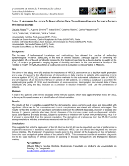
PLANO DE UTILIZAÇÃO DE SOLOS – MASTER PLAN
O Master Plan do Aeroporto do Porto apresenta-se através de 10 desenhos que
reflectem os vários cenários de desenvolvimento do Aeroporto.
Estes estágios de desenvolvimento correspondem a saltos de capacidade desde
da fase actual até aquele que se entende ser o limite de capacidade máximo na
presente localização.
Para a identificação desse limite máximo foram tidas em conta, por um lado, as
condicionantes inultrapassáveis da envolvente externa, e por outro, as próprias
limitações de funcionalidade do sistema aeroportuário.
Prevê-se que este limite, assim definido, possa ser atingido com um
processamento na ordem dos 15 milhões de passageiros/ano.
Os desenhos de nºs impares representam as várias fases de desenvolvimento
correspondendo a cada salto de capacidade.
Os desenhos de nºs pares representam os respectivos planos de utilização de
solos.
Desenhos Nº 1 e 2 – Situação Actual – 5 milhões pax/ano
Identificam as várias infra-estruturas actualmente existentes e que, em grande
parte, resultaram do Plano de Desenvolvimento ASC2000.
Incorpora-se neste layout a 1ª fase de Desenvolvimento do Centro Logístico de
Carga Área (CLCA) que se encontra em fase inicial de construção.
Realça-se, também, a consideração com o nº 28 de um hangar para manutenção
de aeronaves, em fase de estudo preliminar, mas a construir oportunamente.
O sub-sistema de Pista e Taxiways permite processar até 20 movimentos/hora.
Assumindo-se um mix e distribuição de tráfego semelhante ao actual e,
considerando a capacidade já instalada para as restantes infra-estruturas, estimase que o Aeroporto poderá processar volumes de tráfego da ordem do 5 milhões
de passageiros / ano.
Quanto à carga aérea, tendo em conta a construção do CLCA em curso, não é
previsível a existência de qualquer constrangimento no curto e médio prazo.
Esta configuração permite o estacionamento de 35 aeronaves de passageiros e 5
de carga.
Desenhos Nº 3 e 4 – Cenário de Desenvolvimento – 6 milhões pax/ano
Nesta fase existe a necessidade de aumentar a capacidade do sub-sistema de
Pista e Taxiways, pelo que se prevê o prolongamento do caminho de circulação
Poente (A) para Norte, de modo a garantir uma capacidade de processamento de
29 movimentos/hora.
É considerada também a ampliação do CLCA de acordo com a procura, podendo
implicar a afectação de alguns terrenos ainda não contidos no actual perímetro
aeroportuário.
Considera-se ainda a existência de uma Área Estratégica para Desenvolvimentos
Imobiliários (9 A).
No lado nascente do Aeroporto prevê-se a existência de um desenvolvimento
imobiliário que contempla um hotel, uma estação de serviço e abastecimento de
combustíveis e uma zona comercial.
É ainda previsto o aumento da capacidade para estacionamento automóvel.
Nesta fase, a infraestrutura estará preparada para receber a estação de transporte
ferroviário.
Desenhos Nº 5 e 6 – Cenário de Desenvolvimento – 9 milhões pax/ano
Nesta fase torna-se necessário aumentar a capacidade de estacionamento de
aeronaves.
A ampliação da plataforma principal não é possível, uma vez que o seu
prolongamento para Poente feriria as superfícies de protecção da pista actual
(superfície de transição).
Por outro lado, torna-se necessário aumentar a capacidade de pista, o que só será
possível com a existência de um caminho de circulação paralelo a todo o seu
comprimento.
Como solução de desenvolvimento que permite a satisfação dos dois objectivos
atrás identificados, é considerada a translação da pista da sua localização actual
para aquela que se apresenta no seu lado Poente e que corresponderá a um
prolongamento para Norte do actual caminho de circulação A, com a configuração
de pista.
Com este investimento será possível processar na nova pista valores na ordem dos
40 movimentos / hora e ampliar a capacidade para 40 posições de estacionamento
de aeronaves de passageiros.
Deve dizer-se que a pista antiga passará a funcionar como caminho de circulação
paralelo à nova pista.
Aproveitando as suas características, com algumas adaptações de baixo custo
poderá servir como pista de emergência, o que constitui uma enorme vantagem
operacional para o Aeroporto, pois permitirá manter a operação em situações de
inoperacionalidade da pista principal.
A extinção prevista do caminho de circulação A, onde está actualmente localizada
a posição isolada de estacionamento, obrigará à sua relocalização.
Tendo em conta o espaço disponível, considerou-se como localização ideal a que
se assinala em 24.
É considerada a ampliação da placa de estacionamento que serve o CLCA (11), de
5 para 7 posições e ainda a existência de um parque de material de placa que
apoiará essa plataforma.
Em consequência desta ampliação, prevê-se a relocalização da fuel farm para a
posição 23.
Com a relocalização da pista, o actual radar deverá ser também reposicionado.
Nas instalações do terminal de passageiros, para além do reforço de
equipamentos, está prevista a ampliação do edifício Terminal de Bagagem de
Partidas (3).
Desenhos Nº 7 e 8 – Cenário de Desenvolvimento – 11 milhões pax/ano
Ampliação da capacidade para 43 posições de estacionamento de aeronaves de
passageiros, permitindo ao mesmo tempo maior flexibilidade no mix de aviões.
Está prevista a relocalização e ampliação das áreas técnicas de apoio no lado Sul
do Aeroporto (13) e a relocalização das instalações de catering (7).
O espaço libertado pela reinstalação do catering irá permitir uma reformulação das
vias de acesso ao Aeroporto no seu lado Nascente.
Procurando que estas novas vias passem a constituir periferia do domínio
aeroportuário serão criados espaços que poderão servir, nomeadamente, para
aumento da capacidade da actividade de rent-a-car (8).
Do mesmo modo, no lado Sul, serão criadas novas áreas destinadas a reforçar a
capacidade de estacionamento automóvel (6 e 6 A).
Nas instalações do terminal de passageiros está prevista nova ampliação do
edifício Terminal de Bagagem de Partidas (3).
Desenhos Nº 9 e 10 – Cenário de Desenvolvimento – Capacidade Máxima
Está prevista a ampliação da capacidade para 54 posições de estacionamento de
aeronaves de passageiros.
A ampliação das áreas técnicas de apoio no lado Sul do Aeroporto (13).
Criação de novas áreas técnicas de apoio no lado Poente do Aeroporto (18).
Para este estágio de desenvolvimento, assumindo-se que o Terminal de
Passageiros com a configuração anterior esgotou a sua capacidade com o
processamento de cerca de 11 milhões de passageiros/ano, será necessário
proceder à sua ampliação.
Esta será conseguida através do seu desenvolvimento para Sul.
O pier será prolongado, prevendo-se a instalação de mais 7 pontes telescópicas.
Serão construídas novas áreas de partidas e chegadas com os respectivos
curbsides, com tipologias semelhantes às actuais e ligadas ao Terminal principal.
Esta ampliação implicará a relocalização da Torre de Controlo de Tráfego Aéreo
para a posição (15).
! "#$%
&)**
+
! ,* )%-
0
1 23
,* )%$
.
0
/ 2
+
0
7
0
1 23
/
.
4
0
.
- 58
.
540 / 6
8
0
/.
2
7
6
2
=.
.
/
.
1 3
7
>.
7
2
0
1 23
.
=
=
?
<
' (
&)-,
0
4
/ 2
)&9$ : ;%)% <
""
1 &,
7
1
.
&&
0
+
=
.
=
2
2
?
.
0
@
2
A
"!
,* )%-
&&!
+
B
2
2
0
""$!
!&
(
""
/
.
2
7
0
*!
?
2
.
2
2
/
2
/ + AD 8
26
&)-,
0
3
=
C
?
! ,* )%$
!
! ,* )%$
?
:
+
.
o sistema Hayford - Gauss, com datum no ponto central.
3
@
8
@2
0
1
+
2
!
" #" $
%
2
7
<
E
+
F
2
.
+
&
.
06
5& + 6 7
3
1
5&
=
(
2
@
2
C
&
'
&G
%
(
'
&
,- "&$ 9%
&$% )*# %&
"
,* $"& 99
&$- 9*% ,*
9
,* $,# &%
&$- ",& ,*
,
,* $,# ,&
&$- "&$ 9$
*
,* $9# ,)
&$- &%* ,&
-
,* $&9 9&
&$- &-" ,%
$
,* ,$, &$
&$* &-" ,%
%
,* ,)$ )"
&$* -&, #)
)
,* *&" #$
&$* *)- %,
&#
,* *#) $%
&$* *$" #*
&&
,* ,)) ")
&$* *9) *#
&"
,* ,$, --
&$* ,)) %%
&9
,* ,,9 #-
&$* ,-% *9
&,
,* 9*- *"
&$* #&- "-
&*
,* ""& *9
&$, )$, #-
&-
,* #%% ,)
&$, )$, %$
&$
,, )** ,*
&$, )$* -)
&%
,, %%* #,
&$, )#$ $%
&)
,, $%9 %)
&$, %,% 9,
&
'
(
'
"#
,, $*# &%
&$, $&- &-
"& 5 6
,, $9$ ,*
&$, ,$% "&
"" 5 6
,, -$* ,#
&$, ,&- %"
"9 5 6
,, -)$ 9,
&$, 99" 99
",
,, %"- #-
&$, &)$ 9-
"*
,, %&) &-
&$, &-& 9#
"-
,, %#) 9%
&$, &"* &-
"$
,, $)) *)
&$, &#" 9-
"%
,, $%) 9&
&$, #%" $$
")
,, $-9 #9
&$, #99 #&
9#
,, $*9 *9
&$, ##- ",
9&
,, $*" #)
&$9 )$$ %%
9"
,, $*$ -$
&$9 )"" #)
99
,, -)% ,$
&$9 %-9 $*
9,
,, $,* "%
&$9 $9) )*
9*
,, %9" -9
&$9 -,) %9
9-
,, ),* $$
&$9 ")$ #)
9$
,* &&- #"
&$9 "#) )-
9%
,* ,"- &$
&$9 9)* &-
9)
,* "%) ##
&$" -$% ##
,#
,* ,%- ##
&$" -,# ##
,&
,* --" ##
&$9 *-# ##
,"
,* %&9 &&
&$9 *9# )%
,9
,- #,- %"
&$9 $*) #&
,,
,- &9* 9-
&$9 $%" -,
,*
,- #%, &*
&$9 )#9 )#
,-
,- #$# **
&$9 %&, **
,$
,- #*9 *$
&$9 %," $,
,%
,- #,9 *#
&$9 %-, )#
,)
,- #&" -"
&$9 )&* -&
*#
,- &%$ $)
&$, ##$ #$
'
:
(
'
*&
,- 9%, ,#
&$9 )-) ,*
*"
,- 9$$ $,
&$9 %)) #,
*9
,- 9$) $&
&$9 %$% "&
*,
,- 9%# 9%
&$9 %-9 "-
**
,- 9%# -,
&$9 %#" ,*
*-
,- *)% #&
&$9 %&- ")
*$
,- $&) *"
&$, ,*& ")
*%
,- -$$ 9)
&$, ,%% "*
*)
,- -%$ ,%
&$, *&# &)
-#
,- -*& ,%
&$, *9, %)
-&
,- -,# -*
&$, *-% &#
-"
,- -9" #)
&$, *)- "-
-9
,- -&- &9
&$, -*, ,-
-,
,- -&# 9*
&$, -)& ,9
-*
,- *)* -#
&$, $$& -"
--
,- **% ,#
&$, %%* 9#
-$
,- *9* 9&
&$, %$- #%
-% 5.6
,- -"" *%
&$* 99" &*
-) 5.6
,- -*& *&
&$* 9)" "*
$# 5.6
,- $#- ,,
&$* ,9# &#
$&
,- %"& ,"
&$* ,$& ##
$"
,- %9& *#
&$* *"9 #"
$9
,- ,,) "$
&$* %,9 $,
$,
,$ #&% 9$
&$% $)$ *,
C
56H
3
7
@
"& ""
"9
5.6
3
7
@
-% -)
$#
&
)
'
!
" #" $
%
(
'
$*
,- )&# *,
&$$ 9&% &#
$-
,- *%, $,
&$$ 9%# ,*
/
$- 2
$$
$$
9##
%*
,--&$ &$
/
$$ 2
$ %$
$%
&$$ *&# 99
9##
%-
,- "$- $#
/
$% 2
$)
&$$ %&9 ,%
9##
%*
$)
,- #&$ "9
&$$ *&$ -*
%#
,* %), ",
&$$ *,& &)
%&
,* $,9 %)
&$- $** ,,
/
%& 2
%"
%"
9##
%$
,* )-9 *#
%9
&$- ,#% -#
,- 9)# ,)
/
%9 2
%,
&$- ")% "%
9##
%%
%,
,- $-# &)
&$- *9" 9-
%*
,- 9&$ "9
&$$ *&- "9
%-
,- *$- -,
&$$ %#$ *%
%$
,- #9% *,
&$- -)) #-
%%
,- ,-* *9
&$- *%% $,
&
!
'
%)
/
%) 2
" #" $
%
(
'
,- ,&9 -&
&$, $"& ""
)#
9##
&##
)#
,* %", 9&
&$, %99 ))
)&
,* $$9 9%
&$, *-$ %-
/
)& 2
)"
9##
&#&
)"
,* *"9 ,$
&$, 9"$ *)
)9
,* ,9& "%
&$9 %,* %*
/
)9 2
),
9##
&#"
),
,* %,# ,*
&$9 ,*" ,"
)*
,* )-" ,"
&$9 ,") #%
)-
,* )$$ $*
&$9 *#) &)
/
)- 2
)$
9##
	
)$
,- #*, *-
&$9 )&# -#
)%
,- #-- *"
&$9 )$9 &"
))
,- "-9 "-
&$9 )9* ,%
&##
,- &&% )-
&$, $$$ -#
&#&
,* %&% &"
&$, "$& "&
'
(
'
&#"
,* *-% ,)
&$9 *$) #$
	
,* %## ,"
&$9 $*& &%
&
&
* #+
'
#
%
(
'
&%,
,- ,"$ "$
&$, ),# #&
&%*
,- ,#$ &%
&$, %9* #&
&%-
,- ,#- 9%
&$, $%9 ),
&%$
,- ,*& %-
&$, $%& &*
&%%
,- ,%, ,%
&$, $,) 9*
&%)
,- ,), &9
&$, $9, %9
&)#
,- *&& &9
&$, $") *-
&)&
,- *9% $-
&$, $-# -"
&)"
,- ,*$ )#
&$, %9) 9%
&)9
,- *&, ")
&$, %-% )$
&),
,- ,$) %&
&$, )** *#
!! $ !
1
)2 (
&
#
$3
$
, !-
#.
!
/
0I
!%0
=
9##
'
&#,
0
$
(
'
,%#$" ,9
&%--%% -#
=
45 5.
6
!
1
)
)2 (
&
!
3
00
=
5
(
'
&#,
1
56-4 $
@
89-4 $
!6
7
!
(
'
,%#$" ,9
&%--%% -#
56
1
)2 (
&
$ 3
=
0I
9##
'
&#*
0
$
,$)%* *&
&%*&$# #%
48 5.
6
56
!
)2 (
&
!
3
'
&#*
0
0I
=
&###
(
'
,$)%* *&
&%*&$# #%
=
56-4 $
!6
*9-4 $
1
5
7
#
(
1
!
:
3
2 (
&
$ 3
; I
9##
&#-
&#%
&#&#$
&#%
&#)
I
7
5
&#$
7
&#)
'
.
'
=
1
@
(
(
'
,- ,$) -#
&$% 9,% 9#
,- -$# "&
&$% "%# &$
,- --) )-
&$% *%# &$
,- ,$) %-
&$% #,% 9#
=
&#-
&#$6
5 -8 $
!
1
<
:
2 (
&
!
;C I
3
3
"###
&#-
&&#
&#$
7
&&&
'
(
'
&&#
,$ ",$ &*
&%# &)* &*
&&&
,* )#" --
&$- ,99 9"
0
=
=
5
"7
5 -8 $
!6 C
#
(
.
2
2
@
7
1
#
@
(
=9-8 $
.
2
2
@
1
1
0I
>;
&&"
86-8 $
!
*#,"
7
&&,
'
&&*
(
'
&&"
,- 9#& *"
&$* ,-# $)
&&9
,- *&% ,)
&$* -,& $$
&&,
,9 &%& -#
&$) ,"& *%
&&*
,) -9% ,#
&$& -%# )%
0
=
@4 $
@
! 4- 8
?
3
2
(
$
7
!
4-557 %
!
? 5.
#
!
6
(
+!
%0
@
2
@
2
'
C
(
'
&&-
,- 9$, )"
&$% -&* %&
&&$
,* "-) -9
&$" %9) $)
&&%
,* $-# $"
&$" $,* %&
&&)
,- %-- #&
&$% *"& %9
5
!
2
2
@
=
&&9
$
!
#.
!
(
C
!
A
2
%C
@
'
(
'
&"#
,$ 9$9 &&
&%) -%* #*
&"&
," &&# -*
&-" &%, #"
&""
,, $-" *9
&-& -$- *$
&"9
*# #"* ##
&%) &$$ -#
8
" !%0
2
=
3
C
-
1
C
;
1
)C
F
"*##
3
3
2
2
& +6
F
" EJ
2
/
C
'
(
'
&",
,- *9# $9
&$$ *-$ %*
&"*
,- "%& *"
&$$ 9") -"
&"-
,* -#, )&
&$9 $)9 $$
&"$
,* %9& ,#
&$9 )&9 "*
C
1
&G &0
1
3
-
& 5&
G
3
1
,*##
3
3
2
2
2
/
C
'
(
'
-,
,*)*& $*
&$,*," &$
-*
,*-&- &)
&$9%*" $#
--
,--#* %#
&$$)-# &-
-$
,-"$# ",
&$$"$# -)
9
+ %0
2
(
2
@
2
C
'
(
'
&"%
,-%)$ ,9
&$)))) 9$
&")
,*$#- &&
&$$),9 "-
&9#
,*,-, 9"
&$*)#, ,-
&9&
,*#,# %#
&$,9#$ 9#
(
'
&9"
,*#,# %#
&$&&)$ 9)
&99
,-9,# ,-
&$,#*) $*
&9,
,--," #%
&$*)*% -,
'
&9*
=
,$&"$ $-
!
&$$)#& 9"
!%0
2
(
2
@
2
C
-
$
0
,- #-
1
<
&$ H 0
5
&K 6
&)- #-
'
(
'
&9-
,, $-* )#
&)9 #") 9-
%#
,* %), ",
&$$ *,& &)
&9$
,* ),* $-
&$$ *9& 99
&
,- "&$ 9%
&$% )*# %&
$,
,$ #&% 9$
&$% $)$ *,
&9%
,- )," %"
&$% ,#* ,"
/
&9% 2
&9)
9##
&#$
&9)
,- %$) $$
&$% #-" -&
&,#
,- %*& #&
&$$ )"% )&
/
&,# 2
&,&
9##
%-
&,&
,- $%- ")
&$$ *)9 ##
&,"
,- $9) -9
&$$ 9*# %&
$*
,- )&# *,
&$$ 9&% &#
&,9
*9 -)# #9
&)& 9"& *%
0
=
%-
,- *$- -,
&$$ %#$ *%
&#$
,- -$# ""
&$% "%# &$
-
$ G
0
1
<
&$ H
(
H
&)- #'
(
'
&#%
,*"$- &#
&$99#* **
&#)
,*#$% $9
&$"$,9 )*
&&#
,*9*$ "&
&$99&) &%
&&&
,*9$& "#
&$99-" 9,
-
$ 0
-) "*
0
1
<
9* H 0
5
&K 6
"&) "*
'
(
'
&,%
,* "*& -9
&$9 ")# ),
&,)
9% -#- 9#
&*) *-, **
&*#
,$ #$) $-
&*$ ),9 &&
)*
,* )-" ,"
&$9 ,") #%
),
,* %,# ,*
&$9 ,*" ,"
/
), 2
&*&
9##
&#"
&*&
,* -#% $%
&$9 "%& $)
,#
,* ,%- ##
&$" -,# ##
9)
,* "%) ##
&$" -$% ##
&*"
,* ,&" 9*
&$9 9"" )&
/
&*9
&*" 2
&*9
,* 9-* ##
0
&#"
9##
,* *-% ,)
&#"
&$9 9*% -9
=
&$9 *$) #$
-
$
+
-) "*
0
1
<
9* H 0
5
&K 6
"&) "*
'
(
'
)*
,* )-" ,"
&$9 ,") #%
&*,
,$ #9% *#
&*% *&, )$
&**
,$ 9%# -#
&*% ,,) *&
))
,- "-9 "-
&$9 )9* ,%
&*-
,- &#$ 9&
&$9 )-* 9"
&*$
,- #-# 99
&$9 ),# $-
)$
,- #*, *-
&$9 )&# -#
/
)$ 2
&*%
9##
	
&*%
,- #)- -9
&$9 $)% $"
,,
,- &%% $$
&$9 $-# ,-
&*)
,- &## ,"
&$9 $*# #-
/
&*) 2
)-
)-
9##
	
,*)$$ $*
&$9*#) &)
0
	
=
,*%## ,"
@ !
B+
!
&$9$*& &%
%0
=
&, 9K
F
=
2
1
(
C
-
%
5
6H 0
'
F
&
(
'
&-#
,* ,$9 ,*
&%9 9&$ "&
&-&
,* -9* &%
&%# &-& 9#
/
&-"
&-& 2
&-"
,* $#& "9
0
&#-
"###
,- ,$) -#
&#&%# &)# -"
=
&$% 9,% 9#
@
&#"
-
%
G 5
6
0
(
@
2
1
1
&#"
'
(
'
&-9
,* *,$ ),
&$- #,$ ##
-
,* $&9 9&
&$- &-" ,%
*
,* $9# ,)
&$- &%* ,&
,
,* $,# ,&
&$- "&$ 9$
9
,* $,# &%
&$- ",& ,*
"
,* $"& 99
&$- 9*% ,*
&-,
,* $,- #-
&$- ,%$ -%
/
&-, 2
&-*
&-*
"###
,* -&) %9
&$- *," *9
0
&#-
-
=
,- ,$) -#
% 0 5
@
&#-
&$% 9,% 9#
$ 06 0
$0
&#"
'
(
'
&--
,* #,) )9
&$9 ",9 $%
&-$
,9 %)* -)
&$# ,)# &,
&-%
,* "*& -9
&$9 ")# ),
9$
,* &&- #"
&$9 "#) )-
-
% + 5
@
$
6 0
$
&#"
'
(
'
&-)
,) ,,- $)
&%" **- %%
&$#
,% #-% *-
&$) $&# #$
/
&$&
&$# 2
&$&
,% &&- $,
0
&#$
"###
,- -$# "&
&#$
&$) --& 9"
=
&$% "%# &$
-
% E 5
6
0
(
@
2
1
1
&#"
'
&$"
/
(
'
,- $), -"
&$- "%, #*
&$" 2
&$9
"###
&#$
&$9
,- *9, "*
&$- "%, %#
$9
,- ,,) "$
&$* %,9 $,
&$,
,- -,) *$
&$* -$* -%
&#$
,- -$# "&
&$% "%# &$
6 !
B+
C
D
#
%0
&#"
=
8
3
/
3
0
,*##
3
2
2
2
C
(
'
&",
,- *9# $9
&$$ *-$ %*
&"*
,- "%& *"
&$$ 9") -"
&"-
,* -#, )&
&$9 $)9 $$
&"$
,* %9& ,#
&$9 )&9 "*
B+
E
%C
=
6
2
1
*K
1
3
2
2
-*##
2
C
/
3
3
2
'
!
1
2
'
4 !
@2
2
C
(
'
&",
,- *9# $9
&$$ *-$ %*
&"*
,- "%& *"
&$$ 9") -"
&"-
,* -#, )&
&$9 $)9 $$
&"$
,* %9& ,#
&$9 )&9 "*
B+
"#"
C
D
# *
%0
8
=
@2
0
2
1
4
&* ###
'
&$*
?
#D !
(
'
,- &&" ,)
&$* -%# %#
!!+" !
B
" %0
$
2
!
"
=
C
-
1
F
5I
4
6
? 1
H ??F
.
1
2
?
3
2
/
,"##
2
3
3
2
'
C
(
'
&",
,- *9# $9
&$$ *-$ %*
&"*
,- "%& *"
&$$ 9") -"
&"-
,* -#, )&
&$9 $)9 $$
&"$
,* %9& ,#
&$9 )&9 "*
E
1
L
&*##
2
1
@
7
(
2
L
*-##
C
'
? 2(
(
'
&$-
,- ,-% )&
&%& $-$ 9)
&$$
,$ ,,9 $$
&%- %-& %%
&$%
,% )&$ #,
&%- *$) )*
&$)
,$ ),) #&
&%& *"& &,
'
(
'
&%#
,, &%- -,
&-) %,# ,%
&%&
,9 "&% -&
&-, $%& -$
&%"
,, -)& %$
&-, ,)) $,
&%9
,* --- $9
&-) *), ""
E
;
@
1
) 5I
? 2( F
-*$
0 =
4
? 1
6C
H 0 ?F
.
1
'
&$*
E
@
0
=
&%*##
(
'
,- #-$ %,
&$* -%# %#
9#*$
?
=
.
7
7
@
.
.
7
2
.
1
7
=
.
7
@
2
6
7
C
0
7
7
7
7
.
L
J
.6
7
7
2
J
6
7
6
<
6
+
.
.
J
J
1
2
2
6
(
26
8
2
(6
8
2
@
7
7
J
.
7
@
7
7
J
J
( 2
J
2
@
7
1
6
M
7
.
. (
.
2
@
2
&G
7
7
3
&0
5
&
=
.
7
7
.
.
7
7
1
7
7
.
.
=
@
2
7
?@
7
2
6 0
!
7
C
7
.
L
J
.6
7
7
2
J
6
7
.
6 <
.
J
J
6 +
1
2
2
6
(
26 8
2
(6 8
2
7
6 M
?
@
7
7
J
J
.
. (
@
7
.
2
1
7
J
7
"
.
7
@
7
J
( 2
1
2
7
2
@
.
3
.
?
(
=
2
2
>.
.
=
1
@
2
9
?
2
7
1 3
?
7
.
=
2
(
.
7
(
7
1
7
8
:
5
1
@
.
3
@
=
.
3
2 @
7
.
@
2
9
&
:
8
1
.
@
2
C
6
1
.
7
.
7
@
1
1
=
7
.
2
(
7
F
.6
2
=
@
7
2
7
2
.
@
2
2
2 2
"
:
8
@
=
C
6
:
1
07
.6
:
1
)0
6
:
1
0
7
7
3
.
.
.
.
=
:
=
.
2
@
1
.
@
2
C
6
7
7
2
3
2 @
@
2 L
@
J
.6
1
7
7
.
7
7
7
1
2
7
=
.
7
.
7
.
@
2 L
@
@
&
N
.
9
=
=
O 2
"
2
B
O =
/
2
.
=
F
9
.
2
=
=
=
1
.
1
7
>
3
>
6
&
:
= !
!
@
%
2
.
7
7
.
1
6
7
7
0
7
J
7
=
7
2
7
7
.
7
C
.
L
.6
7
7
2
J
6
7
6
<
6
+
.
.
J
1
2
2
6
26
8
2
(6
8
2
7
6
M
@
7
( 2
7
J
@
7
J
7
.
. (
.
2
= !
7
J
7
:
.
7
@
2
J
(
1
"
J
!
7
2
@
3
%
2
7
7
.
7
7
7
.
7
@
2
1
+!
0
=;
1
8
5
0
=; )
0
=;
&K
0
=;
#$
@2
8
5
&)- #-
1
8
&K
1
&K
0
.
&)- #-
@2
6
0
.
6
@2
0
-) "*
8
5
;
,- #-
1
5
C
@2
-) "*
.
"&) "*
6
0
.
"&) "*
6
4
&
=
.
7
2
7
7
@ @
.
.
7
.
1
7
=
7
.
@
2
C
6 0
7
7
7
7
.
L
J
.6
7
7
2
J
6
7
.
6 <
.
J
J
6 +
1
2
2
6
2
(6 8
2
7
7
J
@
7
J
7
.
. (
2
?
7
J
7
"
@
7
@
6 M
.
( 2
1
7
J
(
26 8
2
1
.
7
2
@
.
3
.
.
7
@
@
:
2
6
2
1
7
7
.
7
@
7
1
8
:
7
@2
.
7
.
0
&#" ##
4
2
1
7
7
.
7
@
7
7
1
=
8
*#
@2
7
.
0
&#" ##
"#" ##
?
:
2
1
7
7
.
7
@
7
1
8
7
.
@2
7
0
"#" ##
5
:
1
.
@
2
C
6
:
1
7
1
"
*# P ;
5
P
"
;
6J
7
2
.
2
2
.6
:
1
)
7
1
"
* QP ;
5
P
"
;
6J
8
&
E
2
"!
@
=
1
.
.
7
2
2
7
2
=
6 .
7
1
@
=
5
7
3
=
.
"
+
@
2
2
1
7
2
! - ?- =- @
6
3
7
9
&
M
.
.
.
7
7
2
"
1
=
>
.
.
.
=
&
/
2
2
"
:
7
@
7
. 2
1
@
.
2
2
7
. (
7
3
.
.
. (
(
6 <
(
2
2
C
.
@
&C&####
J
.6
.
6 8
(
1
.
7
.
>
9
2
7
,
/
!&
@
2
. 2
1
7
7
.
. (
@
&
2
7
2
"
:
@
7
>
1
. 2
@
.
(
2
2
7
1
7
3
6
&
N
.
2
1
=
.
. (
7
.
.
"
12
7
0
1
=
.@
2
. (
.
7
. 2
.
1
.
.
2
2
4
&
1
7
7
.
. (
. 2
2
2
.
. 2
. (
"
=
>
1
7
7
9
.
. (
7
6
7
C
1
. (
2
7
J
.6
7
(
>
J
6
,
7
<
>.
23
2
.
.
. (
7
2
2
1
&#
.
.
=
1
=
&
7
1
7
.
7
=
1
7
7
"
2
7
7
7
7
7
.
1
=
1
9
1
.
2
,
/
2
>
2
1
.
.
=
1
=
&#
&
1
.
. (
7
2
.
L
.
.
1
7
2
+
"
0
! &#;"##,
)
'
2
2
+
! &#;"##,
)
'
7
. 2
. (
7
.
.
1
.
1
2
?
+
2
1
. 2
. (
.
.
.
.
(
7
. (
7
7
1
7
7
8
/.
<>.
A
R .
5
/
2
Decreto Regulamentar n.º 7/83, de 3 de Fevereiro
8
/
2
.
=
...\servidão_asc_09-01-2007.dgn 09-01-2007 18:30:52
!
Report for Provision of
Consultancy Services
ANA, Aeroportos de Portugal, SA – Lisboa
Terminal Capacity Review of Oporto International
Airport
05 May 2006
Final Draft
International Air Transport Association
800 Place Victoria, B.P. 113
Montreal, Quebec
Canada H4Z 1M1
Tel: +1 (514) 874 0202
Fax: +1 (514) 874 2662
www.iata.org/ics
2
Executive Summary
IATA was commissioned by ANA to provide a terminal capacity assessment at Oporto International airport. The
focus of the study was to evaluate the current conditions at the airport based on the busy peak hours in 2005; to
calculate the maximum reliable throughput of the existing facilities; and propose possible solutions to ensure capacity
balance and to optimize the terminal capacity while maintaining a good Level of Service. The systems were
reviewed based on IATA’s expanded Rules of Thumb and experience.
An airport is more than just the terminal building. Rather it is a network of inter-related systems that processes
aircraft, passengers, baggage and vehicles. As such, capacity balance amongst all the inter-related systems is a
must to operate an efficient and effective airport.
The study is based on original data supplied by ANA, including plans and busy day flight schedules. This data was
supplemented by information received during the course of a meeting held at Lisbon Airport on the 13.04.06. The
additional parameters, including enhanced load factors and on site observations, were input into the previously
prepared models, generating a set of revised final results with regard to the original Preliminary Report issue.
It is evident from the data supplied that the passenger terminal at Oporto International Airport has been
designed with substantial future capacity expansion in mind. Selective elements of the equipment
installation, including check-in desks, outbound security and baggage reclaim carousels, have only been
provided at 50% of the maximum system configuration afforded by the respective areas. Other, fixed
areas of the terminal system, such as gate lounges have already been sized for a larger demand profile,
reflecting the maximum capacity of the system as a whole.
This situation is reflected in the results of the capacity audit, where there is an asymmetrical distribution
in the sub-system utilisation factors relating to the status of the current installation. This asymmetry is
corrected once the full fit out parameters are input into the model. In order to obtain a more accurate
status the numerical audit was performed twice with the following input data:
The system components as currently installed
The system components within their ultimate maximum configuration
Due to the recent commissioning date of the Oporto Passenger terminal facility and the inherent spare capacity,
which had been built into the design, there are no apparent immediate system constraints or capacity limiting factors.
3
Terminal System Configuration, System Logistics and Market Profile
Aircraft Stands
The aircraft stands main apron is located west to the terminal and East of the runway 17/35. Another small apron is
located south west of the runway but will not be part of the study. The main apron has 31 aircraft stands of 9 are
contact stands. The cargo apron, which is part of the main apron, contains three (3) aircraft stands that can be use
for parking commercial aircrafts if required.
Terminal Configuration
The existing passenger terminal at Oporto International Airport is configured in four levels. The generic process
sequence follows a vertical distribution with the check-in area located at the upper Level 3. After security processing,
the departing passengers descend to Level 2, which accommodates the principal airside concourse serving the nine
air-bridged contact stands along the western façade. The central area is dedicated to Schengen operations with the
southern flank of the southern gate promontory assigned to Non-Schengen traffic.
The main arrivals corridors, located at Level 1, feed passengers into the Level 0 immigration, baggage reclaim and
landside arrivals concourses. Apron Level 0 additionally accommodates two discrete coaching gate lounge clusters
at the southern and northern extremities of the existing building. Both areas accommodate a mix of Schengen and
Non-Schengen dedicated lounges. The northern gate cluster also accommodates a Schengen immigration control
area. The main bank of immigration desks is located at the southern end of the baggage reclaim concourse. The
reclaim area is common to both the Schengen and Non-Schengen traffic streams, which enter the concourse from
the northern and southern ends respectively.
Outbound baggage is processed within a discrete module located at the southern end of the building at Level 0.
Arrivals baggage is processed in an area to the north of the terminal core.
The remainder of the basement area is allocated to sundry technical infrastructure and staff facilities.
Kerb
The terminal is equipped with dedicated departures and arrivals kerbs at Levels 3 and 0 respectively. Each kerb
extends to 200 m with a duplicate road frontage. This provides opportunities for the separate processing of private
car and coach traffic.
Check-in Concourse
The check-in desks are arranged in four island banks located perpendicular to the landside elevation. Each bank
accommodates 15 check-in desks feeding a single collector belt. The size and geometry of each island provides the
opportunity for a future installation of an additional 15 desks (in a mirror configuration) with a second collector belt to
each island. The check-in concourse in its ultimate configuration shall accommodate 120 check-in desks.
The lateral separation between the check-in islands is 22 m. This is adequate in the current configuration, where
each island check-in array is single sided. A future installation of additional check-in desks will create a situation,
whereby the opposing queue depths of 11.0 m each will not permit any lateral circulation between the islands. This is
below the IATA recommended minima and is likely to result in local congestion during future peak hour operations.
Outbound security
The outbound security area has been sized to accommodate 14 X-ray machines and AMD gates. The current
installation consists of 6 units, one of which is dedicated to staff processing.
The outbound security area is accessed directly from the check-in concourse. Six boarding card inspection stations
control access to the security inspection area.
4
Airside Departures Concourse
The airside departures concourse located at Level 2 is accessed by two banks of stairs and escalators descending
from the check-in area at Level 3. The free flow concourse, bounded by commercial and catering outlets on the
eastern perimeter extends the full length of the building. The terminal frontage has two gate promontories at the
northern and southern ends of the airside concourse. The southern promontory accommodates a dedicated
outbound passport control area providing access to Non-Schengen gate lounges at both Levels 2 and 0 respectively.
The northern promontory is only a single level building accommodating both Schengen and Non-Schengen traffic
gate lounges at Level 0. Without access to the arrivals collector corridors at level 1, this area also houses a
dedicated Non-Schengen immigration control area. The structure of the northern promontory has been prepared for
future expansion up to Level 2, to complement the existing provisions in the southern promontory and provide
additional Schengen facilities. Since there were no details available of this future development at the time of
preparing this study, the resulting additional gate lounge areas have not been accounted for in the future system
capacity projection.
Arrivals and Baggage Reclaim Area
The baggage reclaim area contains four indirect feed inclined bed reclaim carousels. The layout of the baggage
reclaim hall has been prepared to accommodate three additional reclaim carousels of a similar size. This shall
require a re-location of the existing immigration area at the southern flank of the reclaim concourse. The future
location of the principal immigration control area, in closer proximity to the access stairs, may result in a limited
queuing area at the head of the passport control desks.
For the purposes of the capacity calculations it has been assumed that each reclaim carousel is capable of
processing three simultaneous flights of a typical aircraft size.
Transfer Logistics
The terminal contains separate provisions for Schengen and Non-Schengen transfer. The Schengen transfer route,
which is located at the northern end of the building, emanates form Levels 0 and 1 terminates at Level 2. The NonSchengen transfers follow a similar path (airside of the immigration control) at the southern end of the building. Both
transfer routes are equipped with dedicated ticketing desks and security X-Ray machines (one each).
Landside Arrivals Concourse
The open plan landside arrivals concourse is located at Level 0. The baggage make-up and despatch area bound
the landside arrivals area on the southern side. There is an opportunity for the future expansion of the landside area
to the north into an area previously occupied by a temporary check-in facility.
Market Profile
The design busy day, recorded on the 29.08.2005, indicates 92 directional movements corresponding to each
departures and arrivals. Of those movements 19 (21 %) serve Non-Schengen destinations / points of origin. The
Non-Schengen destinations are located in the United Kingdom, Switzerland, North Africa, North America and South
America (connecting via Lisbon). The 2005 schedule Non-Schengen and Schengen departures peak hours coincide,
however the Non-Schengen arrivals stream peaks in the morning ahead of the Schengen arrivals stream. The long
haul destinations are currently served outside the combined Schengen and Non-Schengen peak hour periods.
5
Capacity Analysis Methodology
Analysis Methodology
The evaluation of the capacity of the existing Passenger Terminal at Oporto Airport was performed in the following
manner:
Identification of the Prime System Component capacities required meeting the current recorded directional Peak
Hour demand (29 August 2005, Departures 16.00 – 17.00 hrs. and Arrivals 15.00 – 16.00 hrs.)
Extrapolation of the MAXIMUM equivalent Peak Hour Passenger capacity which can be sustained by the
EXISTING Prime System Components, assuming similar process conditions.
Illustration of the UTILISATION LEVELS of the existing terminal system components within the context of the
CURRENT (2005) peak demand loading.
Prime System Parameters
The capacity audit has been conducted on the basis of he IATA Level of Passenger Service Standards. These
provide internationally accredited benchmark targets, whereby the performance of various specific installations can
be directly compared using a common, consistent and quantifiable reference database.
The IATA Level of Service standards are measured on a 6-point descending scale of performance graded from Level
‘A’ to ‘F’. Level ‘A’ represents an excellent level of service, free passenger flow and superior level of user comfort.
Level ‘F’, on the other end of the scale represents a condition of system breakdown, with major process constraints,
cross flow conditions and unacceptable level of service.
The following tabulation provides an indicative summary of the Passenger Service standards related to specific
spatial provisions
A
B
C
D
E
F
SYSTEM
FAILURE
Queue (Check-in)
1.8
1.6
1.4
1.2
1.0
Wait/Circulate
2.7
2.3
1.9
1.5
1.0
Holdroom
1.4
1.2
1.0
0.8
0.6
Bag Claim
2.0
1.8
1.6
1.4
1.2
Gov. Inspection Services
1.4
1.2
1.0
0.8
0.6
This capacity audit, in common with similar studies, has been conducted using IATA Level of Service ‘C’ as the
target parameter for the performance of the prime system components. This level indicates a good level of service
commensurate with stable flow conditions and acceptable levels of delay during peak demand conditions.
The results, using the above stated parameters, are based on the ultimate capacity of the installed systems,
assuming a 100 % utilisation of all the available system resources.
Considering the time required to design, construct and fully commission new or additional terminal facilities, there is
a common expectation of the degradation of Passenger Service Levels during the lifetime of any terminal building.
Extension and remodelling of existing operational facilities also provides additional pressure on the system during the
course of the construction works. It, is consequently, not recommended that a Level of Service Standard below ‘C’ is
adopted as the starting point for any future strategic development policy, since the subsequent and inevitable
degradation as the system reaches maturity, would provide conditions below acceptable standards.
6
Prime System Components
IATA regards the following terminal system components as the key factors which govern the overall capacity of the
facility:
Outbound Security
Check-in desk provisions
Departures passport control
Gate Hold room areas
Arrivals passport control
Baggage reclaim area
Landside concourse
Aircraft Stands
Prime System Variables
The calculation of the system capacity with regard to each individual component specified above is based
on the following parameters:
Demand Profile
o Peak Hour Directional Passenger flow (PHPax)
Fixed installation
o Number of desks, processing counters or reclaim belts (Number)
Floor areas
o Gross floor areas within specific holding sectors (sq.m.)
Process times
o Time taken to process a single passenger (seconds)
System redundancy (Optional)
o Proportional allowance for staffing / system technical constraints
The demand profile was analysed separately for the Schengen and Non-Schengen traffic sectors, where
specific dedicated facilities were required namely:
Outbound Passport Control positions
Departures Gate Lounges
Immigration Control positions
Where the absolute Busy Day peak hour demand did not reflect the a specific peak in a corresponding
traffic sector (Non-Schengen or Schengen) the peak demand of that specific traffic sector was used, in
lieu of the combined figure, to determine the capacity of sector dedicated facilities.
Other areas were audited in terms of the combined peak hour demand (Schengen and Non-Schengen),
reflecting common usage of the facilities.
7
The following graphic illustrates the Schengen boundary conditions in force at the time of this report:
Passenger Traffic
Luxembourg
Spain
Portugal
Austria
Italy
Greece
Denmark
Finland
Germany
Holland
Belgium
France
Sweden
Non - Schengen
Great Britain
Ireland
Poland
Hungary
Czech Republic
Slovakia
Lithuania
Estonia
Latvia
Slovenia
Cyprus
Malta
Customs Boundary
Non - EU
Cargo Traffic
European Union
Schengen
Norway
Iceland
Rumania
Bulgaria
Croatia
Switzerland
Planned Accession
2007
8
The system variables (as currently installed) used in the capacity audit are listed in the tabulation below:
System Component
Passenger Service Level (C)
Schengen
Demand
Profile
Non Schengen
Demand
Profile
Fixed
Installation
Existing
Floor
Area
Process
Time
LOS
System
Redundancy
(sq.m)
Check-In Desks
Proportion of Short Haul Internat.
Movements in peak hour
% of pax in 60 min. before PH
% of pax in 60 min. after PH
1,232.00 PHP (Combined)
100 %
10 movements.
0.00 %
47.00 %
60 units
130.00 sec
0%
Outbound Security
Y – Class Passengers
J – Class Passengers
1,232.00 PHP
80.00%
20.00 %
5 units + 1
staff
15.00 sec
0%
18 units
15.00 sec
0%
Departures Passport Control
Y – Class Passengers
J – Class Passengers
Gate Hold Rooms – Schengen
Peak Hour Aircraft Capacity
Load Factor
Proportion Seated Pax
Proportion Standing Pax
Area per Seated Pax
Area per Standing Pax
Gate occupancy time
503.00 PHP
80.00%
20.00 %
729.00 PHP
Adjusted
80 %
20 %
LOS (C)
1.70
1.20
35 mins.
Gate Hold Rooms – NonSchengen
Peak Hour Aircraft Capacity
Load Factor
Proportion Seated Pax
Proportion Standing Pax
Area per Seated Pax
Area per Standing Pax
Gate occupancy time
Gate Hold Rooms – Total
Peak Hour Aircraft Capacity
Load Factor
Proportion Seated Pax
Proportion Standing Pax
Area per Seated Pax
Area per Standing Pax
Gate occupancy time
7,049.00
503.00 PHP
Adjusted
80 %
20 %
4,122.00
LOS (C)
1.70
1.20
35 mins.
1,232.00 PHP
Adjusted
80 %
20 %
11,171.0
LOS (C)
1.70
1.20
35 mins.
Arrivals Passport Control
Number of aircraft exist doors
559.00 PHP
5 no.
Baggage Claim Units
Proportion of wide body a/c
Occupancy wide body pax
Wide body claim units
Proportion of narrow body a/c
Occupancy narrow body pax
Narrow body claim units
1,230.00 PHP
0.00 %
Arrivals Hall - Landside
Average occupancy time / pax
Av. Occupancy time / visitor
Space per person
Number of visitors / pax
1,230.00 PHP
Aircraft stands - Airside
Buffer time
Turn around time
Number of stands
Schengen peak period AC
movements 18
Non-Schengen peak period AC
movements 8
26 units
20.00 sec
5 units tot.
0%
0%
20 mins.
0 units
100.00 %
20 mins.
4 units
5,662.00
LOS (C)
15 mins.
30 mins.
2.0
0.50
30 mins.
60 mins.
31
9
Capacity Analysis Results
Existing and Maximum Future Capacity
It is evident from the data supplied that the passenger terminal at Oporto International Airport has been
designed with substantial future capacity expansion in mind. Selective elements of the equipment
installation, including check-in desks, outbound security and baggage reclaim carousels, have only been
provided at 50% of the maximum system configuration afforded by the respective areas. Other, fixed
areas of the terminal system, such as gate lounges have already been sized for a larger demand profile,
reflecting the maximum capacity of the system as a whole.
This situation is reflected in the results of the capacity audit, where there is an asymmetrical distribution
in the sub-system utilisation factors relating to the status of the current installation. This asymmetry is
corrected once the full fit out parameters are input into the model. In order to obtain a more accurate
status the numerical audit was performed twice with the following input data:
The system components as currently installed
The system components within their ultimate maximum configuration
System Capacity – Current Installation
The following numerical and graphical tabulation illustrates and compares both the CURRENT (2005 Busy day) peak
Hour demand and the MAXIMUM saturation capacities of the respective terminal sub-systems, based on the
CURRENT EQUIPMENT INSTALLATION. The results are expressed in terms of the utilisation levels of each system
component. These results provide the following indicators:
The ability of the existing installation to respond to the current demand
The residual capacity (2005 date) of each system component
The overall system balances and local constraint conditions, in terms of the mutual relationship of each
consecutive system component.
The following results reflect a capacity profile consistent with both the target LOS (C) and 100% system utilisation
parameters.
OPORTO INTERNATIONAL AIRPORT
SCHENGEN & NON-SCHENGEN TRAFFIC SECTORS
2005
LOS - (C ) - 100%
KEY
SURVEY DATE = 2005
PASSENGER LEVEL OF SERVICE (C )
SYSTEM UTILISATION - 100 %
A
B
C
D
E
F
G
H
J
K
CHECK-IN DESKS
SECURITY CHECK POSITIONS
DEPARTURES PASSPORT CONT.
GATE HOLD ROOMS - SCHENG & NON-SCHENGEN
GATE HOLD ROOMS - SCHENGEN ONLY
GATE HOLD ROOMS - NON-SCHENGEN ONLY
ARRIVALS PASSPORT CONTROL
BAGGAGE CLAIM AREA
LANDSIDE CONCOURSE
A/C STAND PROVISION
1,232
1,232
503
1,232
729
503
559
1,230
1,230
1,732
2,956
2,053
4,527
11,967
7,545
4,411
2,906
4,920
5,662
3,542
42%
60%
11%
10%
10%
11%
19%
25%
22%
49%
MEAN VALUES - DIRECTIONAL PEAK HOUR
1,331
3,827
26%
2,219
0.065%
3,413,333
6,378
0.065%
9,811,795
CURRENT
PEAK HOUR
DEMAND
MAXIMUM
PEAK HOUR
CAPACITY
CURRENT
UTILISATION
FACTOR
(LOWEST VALUES)
COMBINED PEAK HOUR DEMAND
DESIGN INDEX - CHARTER OPERATIONS
EQUIVALENT ANNUAL CAPACITY
10
CAPACITY AUDIT - LOS (C) - 100 % UTILISATION
14,000
Peak Hour Demand
Max Available Capacity
12,000
10,000
8,000
6,000
4,000
2,000
0
A
B
C
D
E
F
G
H
J
K
T E R M IN A L S UB - S Y S T E M
CAPACITY AUDIT - LOS (C) - 100 % UTLISATION
70%
Utilisation Factors
60%
50%
40%
30%
20%
10%
0%
A
B
C
D
E
F
G
H
J
K
T E R M IN A L S UB - S Y S T E M
11
System Capacity – Maximum System Configuration
Due to the recent commissioning date of the Oporto Passenger terminal facility and the inherent spare capacity,
which had been built into the design, there are no apparent immediate system constraints or capacity limiting factors.
The following numerical and graphical tabulation illustrates and compares both the CURRENT (2005 Busy day) peak
Hour demand and the MAXIMUM saturation capacities of the respective terminal sub-systems, based on the
MAXIMUM EQUIPMENT INSTALLATION, which the building has been prepared for.
OPORTO INTERNATIONAL AIRPORT
SCHENGEN & NON-SCHENGEN TRAFFIC SECTORS
FUTURE
LOS - (C ) - 100%
KEY
SURVEY DATE = 2005
PASSENGER LEVEL OF SERVICE (C )
SYSTEM UTILISATION - 100 %
CURRENT
PEAK HOUR
DEMAND
MAXIMUM
PEAK HOUR
CAPACITY
CURRENT
UTILISATION
FACTOR
A
B
C
D
E
F
G
H
J
K
CHECK-IN DESKS
SECURITY CHECK POSITIONS
DEPARTURES PASSPORT CONT.
GATE HOLD ROOMS - SCHENG & NON-SCHENGEN
GATE HOLD ROOMS - SCHENGEN ONLY
GATE HOLD ROOMS - NON-SCHENGEN ONLY
ARRIVALS PASSPORT CONTROL
BAGGAGE CLAIM AREA
LANDSIDE CONCOURSE
A/C STAND PROVISION
1,232
1,232
503
1,232
729
503
559
1,230
1,230
1,723
5,913
5,749
4,527
11,967
7,545
4,411
2,906
8,610
5,662
2,496
21%
21%
11%
10%
10%
11%
19%
14%
22%
69%
MEAN VALUES - DIRECTIONAL PEAK HOUR
1,329
5,686
16%
2,216
0.065%
3,408,718
9,477
0.065%
14,579,487
(LOWEST VALUES)
COMBINED PEAK HOUR DEMAND
DESIGN INDEX - CHARTER OPERATIONS
EQUIVALENT ANNUAL CAPACITY
12
CAPACITY AUDIT - LOS (C) - 100 % UTILISATION
14,000
Peak Hour Demand
Max. Available Capacity
12,000
10,000
8,000
6,000
4,000
2,000
0
A
B
C
D
E
F
G
H
J
K
T E R M IN A L S UB - S Y S T E M
CAPACITY AUDIT - LOS (C) - 100 % UTLISATION
80%
Utilisation Factors
70%
60%
50%
40%
30%
20%
10%
0%
A
B
C
D
E
F
G
H
J
T E R M IN A L S UB - S Y S T E M
13
Conclusions
The capacities of the individual terminal sub-systems indicate a good degree of parity. As anticipated, the mutual
balance of the individual sub-system capacities is markedly improved once the ultimate system installation
parameters are input into the audit. This is fully commensurate with status of a terminal system, where the internal
installation and equipment fit out is phased in line with anticipated demand growth.
The current installation enjoys an average loading in the order of 23% of the aggregate available capacity during the
peak demand period (2005). The exceptions are the check-in desks and outbound security provisions, which are
known to have been installed at half the ultimate capacity.
Substitution of the maximum installation values into the model redresses the imbalances with a resulting average
loading of 16% of the aggregate available capacity during the peak demand period (2005). The departure gate
provisions remain particularity generous with loadings in the order of 11%. The measured areas are illustrated in
Appendix-A to this report.
System Saturation and Strategic Development Plan
The final graph is based on a notional extrapolation of the aggregate directional peak hour demand within three
distinct future growth scenarios (low, median and high). Although this is a very generic approximation, it does give
some indication as to the date when the existing terminal system as a whole will reach saturation capacity at
Passenger Service Level (C).
According to the graph if traffic grows at a median (baseline) of 10% per annum, the terminal system will reach
saturation capacity at Passenger level of Service (C) within the 2020 timeframe.
PEAK HOUR DEMAND GROWTH SCENARIO
12000
8000
SATURATION CAPACITY
15 % ANNUAL GROWTH
6000
10 % ANNUAL GROWTH
6 % ANNUAL GROWTH
4000
2000
19
20
17
20
15
20
13
20
11
20
09
20
07
20
05
0
20
DIRECTIONAL PEAK HOUR PAX
10000
YEAR
14
Baggage Handling System
The evaluation of the outbound baggage handling system focussed upon the following principal considerations:
System capacity to satisfy the busy peak hour demand based upon system variables and data used in the
capacity audit described elsewhere in this document;
Calculation of the maximum reliable throughput of the BHS;
Qualitative review of the system configuration and arrangements for Hold Baggage Screening of outbound
baggage.
System Capacity
The capacity evaluation was based upon data and information provided by ANA and the results of the schedule
analysis. In addition it was necessary to make a number of operational assumptions, which are summarised below:
Peak hour departing passenger volumes are 1,232 passengers / hour (includes both Schengen and NonSchengen);
The number of aircraft movements in the peak hour is currently 10;
Bag Factors are 1.4 for Schengen passengers, and 2.0 for Non-Schengen passengers;
Maximum size of Standard baggage items is 1200 x 750 x 650 mm;
Spacing between bags on the transport conveyors is approximately 150 mm;
The Level 1 EDS screening machines have a throughput capacity of up to 1800 bags per hour;
The Level 3 CT screening machines have a throughput capacity of up to 400 bags per hour;
Average speed of the slowest segment of the in-line transport conveyor system is 1.0m/s.
Peaking of throughput demand within the peak hour has been assumed to be of “medium” severity suggesting a
Peaking Factor of 1.25
Based upon the assumptions listed above the peak hour demand placed upon the outbound system was calculated
to be approximately:
Scenario A: 100% Schengen traffic: 2,156 bags per hour; and
Scenario B 100% Non-Schengen traffic: 3,080 bags per hour.
Baggage Characteristics
It has been assumed that the baggage to be handled by the system will conform to the following characteristics.
These dimensions are governed by the static and dynamic load capacities of hold baggage screening equipment, the
building structural clearances within the allocated BHS spaces together with the anticipated capabilities of BHS
elements such as powered turns, vertical sortation devices and pushers. The figure and table below illustrate the
baggage measurement conventions used to determine the transport system capacity.
Width
Standard
Bag
Dimensions
Maximum
Average
Minimum
Weight [kg]
50
35
5
Length [mm]
1200 1
800
300
Width [mm]
750
400
200
Height [mm]
650
300
50
Length
Height
1
Normal size Golf Bag.
15
Capacity: Transport conveyors
It has been assumed that bags will always be loaded onto the Collector Belt with their long side laid along the axis of
the belt in the direction of travel as illustrated below
The transportation system capacity using
the
belt
speed
and
baggage
configuration illustrated was calculated
for each of the two primary baggage lines
(A and B) to be 44 bags per minute
(2664 bags per hour).
Total system capacity:
44 x 2 = 88 bags per minute (5280 bags
per hour).
Capacity: Hold Baggage Screening System
It has been estimated that each of the three parallel multi-level screening lines will be capable of processing up to
1800 bags per hour, based upon currently available screening system product information, providing a total
screening throughput capacity of 5400 bags per hour.
The time required for the Level 2 screening officer to interrogate the Level 1 image and make a decision to clear the
bag and send it to the make-up area or reject the bag and send it to Level 3 is assumed to be 20 seconds.
Each of the in-line Level 3 CT machines have been assumed to have throughput capacity in the order of 400 bags
per hour, based upon currently available screening system product information, providing a total Level 3 screening
capacity of 1200 bags per hour.
The time required for the Level 4 screening officer to interrogate the Level 3 image and make a decision to clear the
bag and send it to the make-up area or reject the bag and send it to Level 4 is assumed to be 60 seconds.
Similarly, in the absence of data to the contrary, it has been assumed that Hold baggage screening processing and
clear / reject rates are in accordance with IATA recommendations, which are summarised below:
HBS
LEVEL #
1
2
Definition of Screening
Within Level
Fully Automatic Explosive Detection System (EDS) –
inline X-ray Machine.
Staff Operated X-ray Screening image Processor
workstation using enhanced Image Processing software.
3
CT X-Ray Machine Or
Staff Operated Electronic Trace Detection (ETD) System.
(NOTE Level 2 reject Image replicated at Level 3 position
in parallel to ETD system)
4
Reconciliation of Threat Baggage with Passenger (Pax
and Bag Brought to Special Area) Passenger asked to
account for threat image and ETD trace presence
concern. Passenger asked to Open Bag
Cleared Baggage
Directed to:
(Target % of Baggage)
Automatic or Manual
Baggage Sortation System
(70% of Total Flow)
Automatic or Manual
Baggage Sortation System
(25% of Total Flow)
Automatic or Manual
Baggage Sortation System
(4.8% of Total Flow)
Automatic or Manual
Baggage Sortation System
(0.19992% of Total Flow)
Reject Baggage
Directed to:
HBS Level 2
(30% of Total Flow)
HBS Level 3
(5% of Total Flow)
Reconciliation of
Higher Threat Status
Baggage with
Passenger
(0.2% Of Total Flow)
Very High threat
Baggage Sent to
Baggage Bomb
Disposal Unit.
(0.00002% of Total
Flow)
16
Capacity: Baggage Make-up Area
The Make-up facilities should be able to process the allocation of narrow and wide body aircraft proposed to be
resident within the weekly flight schedules. The following summarises IATA recommendations regarding the number
and length of make-up facilities required to process individual narrow and wide-body flights.
Total Make-up
Number of
Ref
Flight Characteristics
length
Make-up
Required to
devices
service each
Flight
1
2
Wide Body
1st Class / Business
2
Economy Class
4
42
5
42
Wide Body
Single class
3
4
Narrow Body
st
1 Class / Business
1
Economy Class
2
28
3
28
Narrow Body
Single Class
The schedule identified up to 10 aircraft movements within the current peak hour, comprising nine “narrow-body,”
and a single “wide-body” aircraft. Based upon current IATA recommendations this would require a total make-up
capacity of:
42 + (9 x 28) = 294 m to be provided by up to (3 x 9) + (6) = 33 individual sort laterals
The BHS has a total of 21 make-up devices, 20 sort laterals, each with a presentation length of approximately 10
metres and a single carousel with a make-up length of approximately 45 metres.
The total makeup length available to support peak hour operations is therefore 240 metres provided by 21 devices,
including a single large carousel.
Based upon IATA recommendations, this indicates a capacity shortfall of 54m of presentation length and 6 individual
sort laterals (assuming that the single carousel is allocated to the make-up of all wide-body flights).
However, it is acknowledged that the rule of thumb IATA recommendations do not take account of the variation of
aircraft size within the narrow or wide-bodied categories. Analysis of the “narrow-body” fleet mix for a typical busy
day indicates that:
Approximately 20% (2 movements in the peak hour) are of Code C3 or B aircraft, such as Embraer 145, CRJ,
and Q300. Baggage make-up for these flights may be performed using a single lateral;
Approximately 20% (2 movements during the peak hour) are Code C2 aircraft, such as Avro RJ, Fokker 100.
Baggage make-up for these flights may be performed using 2 lateral devices; and
Approximately 50% (5 movements in the peak hour) are of code C1 aircraft such as B737-800, A320. Baggage
make-up for these flights may be performed using 3 lateral devices.
Under these conditions the make up requirements may be summarised as:
42 + (5 x 3 x 10) + (2 x 2 x 10) + (2 x 1 x 10) = 255m to be provided by 21 laterals and a single large carousel.
17
This requirement almost exactly matches the current configuration and capacity of the make-up facilities. Additional
flights maybe concurrently processed during the peak hour if baggage sortation protocols are relaxed, for example,
to restrict narrow body Code C1 sort lateral allocation to two laterals per flight, allocation of two or more flights to the
large make-up carousel and intensification of baggage cart loading activities.
Similarly, it is understood that a significant element of the air traffic comprises low cost and charter operations which
are usually single class configurations: This may offer additional opportunities for sortation protocol rationalisation
and reduction in the number s of sort laterals allocated to each flight.
However, any significant increase in the number of peak hour aircraft movements will require the installation of
additional make-up facilities.
Capacity Conclusion
The following summarises the outcomes of the BHS capacity analysis:
System Element
Check-In (60 Counters)
Identified Peak Hour
Demand
Calculated Maximum
Peak Hour Capacity
Current
Utilisation
1,232 passengers
2,956 passengers
42%
100% Schengen
2,156 bags per hour
5173 bags per hour
100% Non-Schengen
3,080 bags per hour
7390 bags per hour
100% Schengen
2,156 bags per hour
5280 bags per hour
41%
100% Non-Schengen
3,080 bags per hour
5,280 bags per hour
58%
100% Schengen
2,156 bags per hour
5400 bags per hour
40%
100% Non-Schengen
3,080 bags per hour
5400 bags per hour
57%
646 bags per hour.
4 screening officers
required
924 bags per hour.
6 screening officers
required
1620 bags per hour.
9 screening officers
required
1620 bags per hour.
9 screening officers
required
108 bags per hour
1200 bags per hour
154 bags per hour
1200 bags per hour
5 bags per hour.
1 screening officer
required
6 bags per hour.
1 screening officer
required
48 bags per hour.
1 screening officer
required
48 bags per hour.
1 screening officer
required
Transportation System (Line A and B)
Hold Baggage Screening
Level 1 (100% of total bag flow)
Assumes individual EDS capacity of 1800
bags per hour
Level 2 (30% of total bag flow)
Assumes 20 seconds to analyse bag image
and make pass / fail decision
100% Schengen
100% Non-Schengen
92%
86%
Level 3 (5% of total bag flow) Assumes
individual CT capacity of 400 bags per hour
100% Schengen
100% Non-Schengen
9%
13%
Level 4 (0.2% of total bag flow)
Assumes 60 seconds to analyse bag image
and make pass / fail decision
100% Schengen
100% Non-Schengen
92%
86%
18
System Element
Identified Peak Hour
Demand
Calculated Maximum
Peak Hour Capacity
Current
Utilisation
Baggage Make-up
20 sort laterals and a single carousel
10 Movements per peak hour (9 Narrow and
a single wide-body)
Evaluation against IATA recommendations
Revised Evaluation
42m + (9 x 28m) =
294m
42m + (21 x 10) =
252m
45m + (20 x 10) =
245m
45m + (20 x 10) =
245m
125%
103%
In conclusion, it may be stated that the check-in, transportation and hold baggage screening elements of the BHS
have a significant amount of unused capacity: Average system utilisation may be considered to be in the order of
40%– 50 %, depending on the mix of Schengen and Non-Schengen passengers.
However based upon the available information, the make-up facilities are currently fully utilised and will require
augmentation in order to cope with any significant additional traffic volume.
The planned installation of an additional 60 check-in counters will add the capability to process up to 5900
passengers (which equates to 8260 Schengen destination bags). However, this additional capacity to induct
baggage to the BHS far exceeds the ability of the current system to process it effectively.
System Configuration
Notwithstanding the concern over baggage make-up facility capacity, the general design and layout of the BHS has
been carefully considered to align with current industry norms and best practices. There are no apparent
constrictions or bottlenecks in the flow path and all major components have been configured to provide good working
conditions for baggage handling staff and screening system operators.
The inclusion of cross-over transportation links between the main transportation feeds from check-in to baggage
room (Line A and Line B) is an excellent way of balancing load and providing operational contingencies in the event
of a downstream planned or unplanned maintenance event.
19
Ergonomic Considerations
Baggage system interfaces with the baggage handling staff within the baggage hall should be ergonomically
designed. Baggage off-load levels within the baggage halls should be designed to be ergonomically suited to the
local workforce and should adopt best international working practices, such that the risk of off loading injuries should
be minimised. Similarly, attention is drawn to the requirement to ensure that heavy baggage lifting equipment is
provided where it is envisaged that excessively heavy baggage will be transferred from the BHS to awaiting
containers. This applies not only the baggage handling work areas, but also to the provision of maintenance access
ladders, platforms, and catwalks.
Bag Sortation
It has been assumed that bag sortation will be achieved through the use of automated bar code reader devices
installed ahead of the Level 1 EDS screening machines. It was not apparent from the information provided as to what
arrangements had been included for the manual coding of bags whose labels were unreadable or were mis-read by
the scanners, other than direct the affected bag to the Level 5 Screening Station where it may be manually examined
before being directed to the appropriate make-up device.
Over Size Items
It is not apparent from the information provided as to what arrangements are planned to handle over size or out of
gauge items, although it is acknowledged that the specification of a baggage belt width in the order of 900-950 mm
will provide some capacity to handle individual items that are outside of the Standard Baggage dimensional
envelope.
Hold Baggage Screening System:
The arrangements for Hold Baggage Screening are in accordance with industry norms and best practices. The multilevel in-line approach will ensure that baggage screening does not impose any restriction upon baggage flow during
peak hour operations and the inclusion of three parallel screening lines provides a high degree of redundant capacity
in the event of a failure an individual screening machine (Level 1 or Level 3).
The location of the screening control room housing the monitoring work stations adjacent to the baggage hall will
enable rapid response of screening operators for manual intervention to address a specific screening problem as
required. The baggage flow path up to and beyond Level 5 reconciliation of the bag and passenger is very clear and
well thought out. Of particular note is the provision of a Threat Bag quarantine and evacuation facility.
However, there would appear to be a significant over-capacity with regard to Level 3 screening via the use of three
In-line integrated CT machines. Notwithstanding the fact that specific throughput and capacity data was not available
to IATA, machines of this type are usually capable of processing up to 400 bags per hour which would suggest that a
single machine would have provided sufficient capacity to meet projected demand for the foreseeable future.
A second machine may be justifiable in order to address any latent concerns over machine reliability and provide a
high degree of surge capacity but based upon the available information, the inclusion of a third CT machine may be
considered excessive.
20
Conclusion
The design of the outbound baggage handling system has been carefully considered to conform to current industry
norms and best practices, including IATA recommendations regarding system performance, and configuration to
promote a safe, secure and efficient operating environment.
The current traffic schedule imposes a projected outbound demand of between 2156 and 3080 bags per hour, which
is dependant upon the mix of Schengen and non-Schengen flights being processes concurrently.
The hold baggage screening configuration should be reviewed with the objective of rationalisation of the number of
CT machines from three to two.
A conservative estimation of the overall system capacity is in the order of 5400 bags per hour based upon the hold
baggage screening process configuration, which indicates that the system will initially have a 40 - 57% utilisation rate
during peak hour operations.
However, the baggage make-up facilities are very closely matched to the current traffic volume and mix, and
notwithstanding the ability to process additional flights through the relaxation of sortation protocols, for example, to
restrict narrow body Code C1 sort lateral allocation to two laterals per flight, allocation of two or more flights to the
large make-up carousel and intensification of baggage cart loading activities, any significant increase in the number
of aircraft movements during the peak hour will require additional make-up capacity both in terms of make-up
presentation length and the number of individual sort laterals.
CAPACITY AUDIT - UTLISATION FACTORS
120%
1.4 bag/pax Schengen
2.0 bag/pax Non-Schengen
100%
CAPACITY LOADING
80%
60%
40%
20%
0%
Check-in
Collector Belt
Level 1
BHS SUB-SYSTEMS
Level 3
Make up Area
21
Aircraft Stand System
The aircraft stand (gate) system is a key interface between the aircraft flow and the passenger flow. The number of
aircraft and where the aircraft are processed will affect the performance and capacity of the apron and passenger
terminal. Realistic stands requirements are essential to develop efficient and cost-effective apron/terminal concepts.
Determining aircraft stand capacity and requirements largely depend on predicting the impact of projected airline
schedule. Therefore a typical busy summer day was selected to conduct the capacity analysis. Please refer to the
appendix B for more detailed information on the hourly distribution of aircraft movements in 2005.
The next figure illustrates the overview of the available apron areas and the gate supply (2005) used for the analysis.
Code E1
Code E2
Code D1
Code D2
Code D3
Apron stands allocation is not only based on aircraft size
configuration, rules and procedures are also important
factors determining the practical capacity of the system. The
next figure shows the fleet mix derived from the typical 2005
summers busy day.
Code C1
Code B
17%
Code C2
Code C3
Code B
Code D1-2
7%
Code C3
5%
Code C1
54%
Code C2
17%
22
The assignment of the individual flights was governed by the priority list that was provided by ANA. The
objective being to maximize the use of the Main apron stands.
Preferential stand selection: Contact Stands.
Priority is given to larger aircrafts on the large and MARS Stands.
Small code C and B aircraft types are not allowed on contact stands due to the
loading bridge restriction.
The cargo flights are given priority at the cargo stands but commercial flights can use
to cargo stands if required.
Gate restrictions and gate adjacency restrictions as provided by ANA.
A blocking time of 30 minutes is add to the aircraft occupation time at the stand to
take into account normal schedule variation.
Guided by ANA operational parameters and gating needs, and using the approved gate definitions and the planning
schedules, an assignment of flights have been undertaken. It provides an assessment of the ability of the facility to
handle the proposed flight schedule. IATA’s model (Total AirportSim) was used to assign the aircraft demand to
stands determining requirements and limitations.
The 2005 peaks illustrated in the hourly distribution of aircraft movements graph from Appendix B p.8, ire translated
to a gate usage profile illustrated in the following image (b and c). The peak gate occupation rate (a) is explain by
having many overnight flights at the airport.
25
(a)
(c)
20
(b)
Stands
15
10
5
0
0
1
2
3
4
5
6
7
8
9 10 11 12 13 14 15 16 17 18 19 20 21 22 23 24
With a residual capacity of about 30% the gate system can easily handle the projected 2005 + 50% demand.
Although no code E aircraft was numbered in the base 2005 schedule, provision for four (4) code E aircraft stands
are made available and should suffice to handle the 2005 + 50% demand.
23
The next graph and figures illustrate the apron stand system at saturation and beyond (2005 +60%). The 2005 +
60% peaks illustrated in the hourly distribution of aircraft movements graph from Appendix B p.8, are translated to a
gate usage profile illustrated in the following graph (b and c). With the growing demand the daily gate usage will
increase faster than the overnight requirement. Therefore, the peak gate occupation (b) surpasses the peak gate
utilisation (a).
40
(b)
(a)
35
(c)
30
Stands
25
20
15
10
5
0
0
1
2
3
4
5
6
7
8
9 10 11 12 13 14 15 16 17 18 19 20 21 22 23 24
To accommodate all the flights during the morning peak, up to 36 aircraft stands are required. However,
using the full potential of the available cargo stands, only three (3) commercial code B stands and one
cargo code D stand are required. The breakdown is as follows:
5 code D2 (48m) stands
3 code D3 (B757) stands
14 code C1 (36m) stands
6 code C2 (28m) stands
8 code C3 and B (<28m) stands
The next graph shows the hourly Schengen contact stand
occupation profile. The Schengen flight sector with over 20
movements during the peak period fully utilised the contact
stands.
6
5
On the other hand, the International contact stands are less
busy. However and because of the operational time w window
of international flights it is difficult to fill the gaps with extra
flights.
5
S tan d s
4
3
2
1
0
4
0
1
2
3
4
5
6
7
8
9 10 11 12 13 14 15 16 17 18 19 20 21 22 23 24
S tan d s
3
2
1
0
0 1
2 3 4 5
6 7 8
9 10 11 12 13 14 15 16 17 18 19 20 21 22 23 24
24
The following figure shows an aerial view snap shot of the main apron occupation at 6h30 am.
: Incoming arrival or an
aircraft has just left within
30 minutes.
: The stand aircraft type
restrictions/ regulations do
not permit any of the
overflow flights to be
parked at the stand.
: Time gap between two
flights is not sufficient to
accommodate one of the
aircraft allocated to the
overflow area.
Virtual Overflow area showing
the missing stands
25
Conclusions
The aircraft stand system with 31 stand positions is at 70% of the capacity using a typical 2005 busy summer day. It
can easily accommodate the current traffic plus 50% (5.0 MAP). Up to three additional code B stands are required
when the traffic growth reaches 60% (5.4 MAP). However, the cargo apron maybe at capacity before the airport
reaches 5.0 MAP.
By implementing local operational
procedures such as towing aircraft
that has long ground occupation
time to a remote location (cargo
apron or the west apron), and by
adding some flexibility to the actual
apron usage such as introducing
MARS (Multiple Apron Ramp
System) at the remote S-Sixties
stands (see the next figure) the
apron stand system would be able
to handle a 60% traffic increase with
only minor investments.
This figure shows that 6 Code B
aircrafts can be parked where 4
Code C aircrafts are parked.
Although the apron stand system has the capacity of accommodating a 60% traffic increase it is seams
that the taxi - runway system may become the airport capacity limiting factor. Priority should be made to
increase the runway throughput before investing in the apron expansion by improving to the runway taxiway system such as extending the taxiway F to the runway end or relocating the runway to the west
to fully take advantage of a dual taxiway system.
All the stand assignment Gant charts can be found in the appendix C1 to C4, where C1 is the actual
2005 demand, C2 the 2005 + 40% demand, C3 the 2005 + 50% demand and appendix C4 the 2005 +
60% demand. The next pages figures shows part of the Gantt chart of the 2005 + 60% stands allocation
as for example.
26
27
28
29
EUROPEAN ORGANISATION FOR THE SAFETY OF
AIR NAVIGATION
EUROCONTROL
Assistance to ANA
Airports
Airside Capacity
Assessment of
Porto Airport
Edition
Edition Date
Status
Class
:
:
:
:
1.4
24 August 2005
Released Issue
Restricted audience
This page is intentionally left blank
DOCUMENT IDENTIFICATION SHEET
DOCUMENT DESCRIPTION
Document Title
EUROCONTROL Assistance to ANA Airports
Airside Capacity Assessment of Porto Airport
EATMP Infocentre Reference: 05/07/20-1
PROGRAMME REFERENCE INDEX:
EDITION:
1.4
Project Manager : Bruno Desart, DAS/AEM
EDITION DATE:
24.08.2005
Project Team : Bruno Desart, Laura Serrano Martin, Kamen Peshev
Abstract
In a letter dated 22 May 2000, Mr. Fernando Melo Antunes, President of the ANA Board, requested
EUROCONTROL to conduct a runway capacity study for four Portuguese Airports, namely Lisboa,
Faro, Madeira and Porto. The aim of this request was to assist the Airports Authority in Strategic
Airport Planning and to support them in the implementation of the EC Regulation 95/93 on airport Slot
Co-ordination.
This document concerns the fourth airport, Porto Airport (Aeroporto Franscisco Sa Carneiro). This
study is based on specific baseline scenarios and uses the EUROCONTROL Commonly Agreed
Methodology for Airport airside Capacity Assessment (CAMACA). Both the baseline scenario and
the analytical model were reviewed and accepted by the Technical Team that included
representatives from ANA, NAV and EUROCONTROL.
Capacity
CONTACT PERSON:
Keywords
Porto Airport
Airside
Bruno Desart
TEL: +32 2 729 3137
CAMACA
DIVISION:
DAS/AEM
DOCUMENT STATUS AND TYPE
STATUS
Working Draft
Draft
Proposed Issue
Released Issue
;
CATEGORY
Executive Task
Specialist Task
Lower Layer Task
;
CLASSIFICATION
General Public
EATMP
;
Restricted
ELECTRONIC BACKUP
INTERNAL REFERENCE NAME:
HOST SYSTEM
Microsoft Windows
N:\AirsideCapacityStudies\Portugal\Porto - OPO - LPPR\OPO
EUROCONTROL Study 2003\OPOFinalReport.1.42.doc
MEDIA
Type: Hard disk
Media Identification:
SOFTWARE
Word 97 – SR2
EUROCONTROL Assistance to ANA Airports
Airside Capacity Assessment of Porto Airport
DOCUMENT APPROVAL
The following table identifies all management authorities who have successively approved
the present issue of this document.
Prepared
Stakeholder
Organisation
/
EUROCONTROL
Official’s Name:
Position:
Mr. Bruno DESART
Manager Airport
Capacity & Delay
Analysis
Date & Signature:
Operational
Manager Porto
Airport
Mr. Rui ALVES
Reviewed
ANA
Mr. João NUNES
NAV
EUROCONTROL
Head of Operations
Division
Mr. Pedro Manuel
BARROS PRATA
Head of Porto ATS
Mr. Ken REID
Head of Airports &
Environment
Management
Business Division
Cpt. J. Ivo da SILVA
Technical Services
Director
Mr. Jaime
VALADARES
Advisor ANA Board
Approved
ANA
NAV
EUROCONTROL
Edition : 1.4
Mr. Abel PARAIBA
Mr. Bo REDEBORN
Director Safety and
Operational
Performance
Director ATM
Strategies
Released Issue
Page iv
EUROCONTROL Assistance to ANA Airports
Airside Capacity Assessment of Porto Airport
DISTRIBUTION LIST
The following table identifies the direct stakeholders as well as all the other participants to
the study. Their co-operation is gratefully acknowledged.
ANA
Mr. Walter W. MARQUES – President of ANA Board
Mr. Rui VERES – ANA Board Member
Mr. Casimiro PIRES – ANA Board Member
Mr. Jaime VALADARES – Advisor to ANA Board
Mr. João Ivo DA SILVA – Technical Services Director (DSTE)
Mr. João NUNES – DSTE/Head of Operations Division
Mr. Fernando GASPAR VIEIRA – Director Porto Airport
Mr. Rui ALVES – Operational Manager Porto Airport
Mr. Antonio LOUREIRO – Head of Porto Airport Operations
Mr. Joaquim CARVALHO – Deputy Head of Porto Airport Operations
Mr. Paulo Jorge F. PEREIRA – Airport Operations Expert
NAV
Mr. Abel PARAIBA, Director Safety and Operational Performance
Mrs. Maria da Conceição Lobão FERREIRA, Lisbon FIR OPS Director
Mr. Americo MELO
Mr. Pedro Manuel BARROS PRATA – Head of Porto ATS
Mr. Jesus CONDE – Technical consultant / ATM expert
Mr. Rui NEVES
Mr. Alvaro FERRAO
EUROCONTROL
Mr. Bo REDEBORN - Director ATM Strategies
Mr. Ken READ – Head of Airports & Environment Management
(DAS/AEM)
Mr. Kenneth EIDEBERG - Head of Stakeholder Implementation Service
(SIS)
Peter ERIKSEN
(DAS/AEM)
–
Acting
Airport
Operations
Domain
Manager
Razvan BUCUROIU –Capacity Enhancement Manager (SD/ESC/CEF)
Etienne FRANCOIS – LCIP Service Manager
Mr. Bruno DESART – Manager Airport Capacity & Delay Analysis
Mr. Juan CARRASCO GUILLEN - Area Manager (WEST) & CIP EAS
Projects
Ms. Laura SERRANO MARTIN – Airport Modelling & Statistics
Mr. Kamen PESHEV – Software Expert
Edition : 1.4
Released Issue
Page v
EUROCONTROL Assistance to ANA Airports
Airside Capacity Assessment of Porto Airport
EXECUTIVE SUMMARY
In a letter dated 22 May 2000, Mr. Fernando Melo Antunes, President of the ANA Board,
requested EUROCONTROL to conduct a runway capacity study for four Portuguese Airports,
namely Lisboa, Faro, Funchal and Porto. The purpose of this request was to assist the
Airports Authority in Strategic Airport Planning and to support them in the implementation of
the EC Regulation on airport Slot Co-ordination.
This document addresses capacity analysis for the fourth of these airports, Porto Airport
(Aeroporto Franscisco Sa Carneiro), based on the operational conditions in 2003. It reports
the airside capacity values and ground traffic efficiency analysis, based on specific baseline
scenarios and using the EUROCONTROL Commonly Agreed Methodology for Airport airside
Capacity Assessment (CAMACA). Both the baseline scenarios and the analytical model
were reviewed and accepted by the Technical Team that included representatives from ANA,
NAV and EUROCONTROL.
Based on data collected in 2003, the following conclusion could be drawn:
Declared capacity at Porto Airport was 14 movements per hour. This study showed
that the runway system capacity was 19 movements per hour during outbound traffic
peak and 17 movements per hour during inbound traffic peak when RWY 17 was
used in mixed mode of operations. When RWY 35 was used, the hourly capacity
was 24 movements in departure peak and 16 movements in arrival peak.
Although the airport was equipped with an on-site monopulse 15-RPM SSR radar,
the capacity at Porto Aiport was predominantly affected by the in-trail separations (8
NM on RWY 17 and 10 NM on RWY 35). In inbound traffic peak, capacity relating to
RWY 17 operations could be increased by 39% if radar separation was reduced to 5
NM, and to 55% if it was reduced to 4 NM. Below 4 NM on RWY 17, it was
suggested to focus on lower arrival runway occupancy time. As far as RWY 35 was
concerned, the following capacity increases were assessed for inbound traffic peak :
69% if radar separation was reduced to 5 NM, 95% if reduced to 4 NM, and 130% if
reduced to 3 NM.
The need to taxi on RWY 35 in order to join the departure queue of RWY 17 was
another factor affecting capacity. In order to mitigate the impact of these operations,
the five following planning options were analysed: the construction of a new holding
bay close to threshold 17, the extension of Western taxiway up to 2400 and 2700 m,
the extension of Easter taxiway up to 2500 and 2700 m. The extension of Eastern
taxiway was the most promising option from both capacity and safety points of view,
because it avoided crossing runway operations. Taxiway extension had no
significant impact on RWY 35 operations, as long as heavy jets were operated out of
peak.
As far as the apron S was concerned, its configuration enabled to accommodate 16
aircraft per hour when parking positions S10 and S55 were not split, and 18 aircraft
per hour when spittable stands were used. The new design of Apron S was expected
to increase sustained capacity to 33 aircraft per hour, for the 32 parking positions,
should type of service remain unchanged.
A ground traffic efficiency is also reported, concluding that ground traffic was fluid and
efficient, and did not constrain airside operational capacity.
Edition : 1.4
Released Issue
Page vi
EUROCONTROL Assistance to ANA Airports
Airside Capacity Assessment of Porto Airport
In brief, the runway and Apron S were the two major components in the determination
of Porto airside capacity in 2003, to be considered with equal importance. The new
investment on Apron S would be fully beneficial if runway capacity was improved
through reduction of in-trail separation combined with Eastern taxiway extension to
increase departure capacity on RWY 17.
It is to be noted that, since 2004, NAV reduced in-trail separation to 7 NM on both runway
orientations, what entailed a theoretical capacity increase of more than 11% for equally
balanced traffic mix for RWY 35 operations. This resulted in an increase of declared
capacity by 2 additional movements.
It is also to be noted that, according to AIP’s, runway exit F is not available any longer for
landing on RWY 17. It is recommended to investigate the impact of this operational change
on capacity in the scope of a next capacity analysis study.
Edition : 1.4
Released Issue
Page vii
EUROCONTROL Assistance to ANA Airports
Airside Capacity Assessment of Porto Airport
COPYRIGHT NOTICE
This document has been produced by the EUROCONTROL Agency for the ANA Board.
Copyright is vested with the EUROCONTROL Agency.
Copy or disclosure to any other party is subject to prior consent in writing by the
EUROCONTROL Agency.
ACRONYMS
ANA
Portuguese Airports Authority – Aeroportos de Portugal SA
ANSP
Air Navigation Service Provider
CAMACA
EUROCONTROL Commonly Agreed Methodology for Airport airside Capacity Assessment over
ECAC
CTOT
Calculated Take-Off Time
FAF
Final Approach Fix
LPPR
Porto Airport (Aeroporto Franscisco Sá Carneiro) – ICAO Code
LUPT
Line-up Time, defined as “the time elapse measured between the crossing of the stop bar and
the moment that the aircraft is fully lined up.” (AOT4 WP3 RACE TF)
MTOW
Maximum Take-Off Weight
NAV
Navegação Aèrea de Portugal, E.P.
NOTAM
Notice to Airmen
OM
Outer Marker
OPO
Porto Airport (Aeroporto Franscisco Sá Carneiro) – IATA Code
(P)RET
(Perpendicular) Runway Exit Taxiway
RAT
Runway Access Taxiway
ROTA
Arrival Runway Occupancy Time, defined as “the time elapse measured between the crossing of
the threshold and the aircraft’s tail vacating the runway edge” (AOT4 WP3 RACE TF)
ROTD
Departure Runway Occupancy Time, defined as “the time elapse measured between the
crossing of the holding stop bar and the main gear off the runway.” (AOT4 WP3 RACE TF)
RRET
Rapid Runway Exit Taxiway
RWY
Runway
SSR
Secondary Surveillance Radar
STATFOR
EUROCONTROL Air Traffic Statistics and Forecast Service
TAP
Transportes Aéreos Portugueses
THR
Runway Threshold
TORA
Take-Off Run Available
TOFT
Take-Off Time, defined as “the time elapse measured between the moment that the departure is
fully lined up and the moment that the main gear is off the runway, (including pilot response
times, ATC clearance time equivalent and separation time equivalent).” (AOT4 WP3 RACE TF)
TWY
Taxiway
VLA
Very Large Aircraft (i.e. A380)
Edition : 1.4
Released Issue
Page viii
EUROCONTROL Assistance to ANA Airports
Airside Capacity Assessment of Porto Airport
DOCUMENT CHANGE RECORD
The following table records the complete history of the successive editions of the present
document.
Edition
Date
Status
Reason for Change
& Page/Section affected
Edition : 1.4
0.1
27/06/03
Working draft report
0.2
07/07/03
Draft Report
Sections 2.3, 4.2, 5.2 and
related to Sensitivity
Analyses
0.3
22/07/03
Draft Report
Typographical review
1.0
09/10/03
Proposed Issue
External review
1.1
26/02/04
Proposed Issue
Complement results with
new data collection by
ANA and NAV
1.2
05/05/04
Proposed Issue
Decision made at
meeting 19/02/04
1.3
12/07/05
Proposed Issue
Decision made at
meeting, 12/07/2005,
concerning new radar
provision; Executive
Summary; Conclusion
1.4
24/08/05
Released Issue
Executive Summary and
Conclusion based on
update of information
from NAV, 9 August 2005
Released Issue
Page ix
EUROCONTROL Assistance to ANA Airports
Airside Capacity Assessment of Porto Airport
TABLE OF CONTENTS
DOCUMENT IDENTIFICATION SHEET....................................................................................................... iii
DOCUMENT APPROVAL..................................................................................................................................iv
DISTRIBUTION LIST ..........................................................................................................................................v
EXECUTIVE SUMMARY...................................................................................................................................vi
COPYRIGHT NOTICE ..................................................................................................................................... vii
ACRONYMS ....................................................................................................................................................... vii
DOCUMENT CHANGE RECORD ................................................................................................................. viii
TABLE OF CONTENTS......................................................................................................................................ix
1.
INTRODUCTION........................................................................................................................................ 1
1.1
1.2
1.3
1.4
2.
BACKGROUND ........................................................................................................................................ 1
OBJECTIVE AND SCOPE ........................................................................................................................... 1
DOCUMENT STRUCTURE......................................................................................................................... 2
REFERENCE DOCUMENTS ....................................................................................................................... 2
SCENARIO DEFINITION.......................................................................................................................... 3
2.1
PORTO AIRPORT – THE CONTEXT ........................................................................................................... 3
2.2
BASELINE SCENARIOS ............................................................................................................................ 4
2.3
SENSITIVITY ANALYSES ......................................................................................................................... 5
2.3.1 Sensitivity Analyses for the Runway.................................................................................................. 5
2.3.2 Sensitivity Analyses for the Apron Configuration ............................................................................. 7
3.
ANALYSIS ENVIRONMENT.................................................................................................................... 8
3.1
THE COMMONLY AGREED METHODOLOGY FOR AIRPORT AIRSIDE CAPACITY ASSESSMENT (CAMACA)
8
3.2
DATA COLLECTION & INPUTS ................................................................................................................ 9
3.2.1 Aircraft Classification ....................................................................................................................... 9
3.2.2 Choice of a Representative Traffic Sample ..................................................................................... 10
3.2.3 Fleet Mix Analysis........................................................................................................................... 11
3.2.4 Aircraft Performance Data & Runway Occupancy Time Data Collection ..................................... 11
3.2.5 ATC Separations ............................................................................................................................. 14
3.2.6 Apron Configuration ....................................................................................................................... 14
3.2.7 Turnover and Stand occupancy Times ............................................................................................ 15
3.2.8 Assumptions for Ground Traffic Efficiency Analysis ...................................................................... 17
3.2.9 Stand Usage .................................................................................................................................... 18
4.
RUNWAY SYSTEM CAPACITY ASSESSMENT................................................................................. 19
4.1
BASELINE SCENARIOS .......................................................................................................................... 19
4.1.1 OPO2003-RWY17 Baseline Scenario ............................................................................................. 19
4.1.2 OPO2003-RWY35 Baseline Scenario ............................................................................................. 20
4.2
SENSITIVITY ANALYSES ....................................................................................................................... 22
4.2.1 New holding bay at THR 17 ............................................................................................................ 23
4.2.2 Western TWY extension................................................................................................................... 24
4.2.3 Eastern TWY extension.................................................................................................................... 26
4.2.4 Impact of radar separation ............................................................................................................. 28
5.
APRON CAPACITY ANALYSIS............................................................................................................. 31
5.1
5.2
6.
GROUND TRAFFIC EFFICIENCY ANALYSIS................................................................................... 33
6.1
6.2
7.
BASELINE SCENARIO – THE 2003 APRON S CONFIGURATION .............................................................. 31
SENSITIVITY ANALYSIS – FUTURE APRON S CONFIGURATION ............................................................. 31
BASELINE SCENARIO OPO2003-TWY17 ............................................................................................. 33
BASELINE SCENARIO OPO2003-TWY35 ............................................................................................. 34
CONCLUSION & RECOMMENDATIONS........................................................................................... 36
Edition : 1.4
Released Issue
Page x
EUROCONTROL Assistance to ANA Airports
Airside Capacity Assessment of Porto Airport
ANNEX 1.
FLEET MIX ANALYSIS ......................................................................................................... 38
ANNEX 2.
ROT DATA COLLECTION ................................................................................................... 39
ANNEX 3.
ATC SEPARATION................................................................................................................. 42
ANNEX 4.
STAND OCCUPANCY DATA COLLECTION .................................................................... 43
ANNEX 5.
RUNWAY CAPACITY ASSESSMENT – BASELINE SCENARIOS................................. 44
ANNEX 6.
RUNWAY CAPACITY ASSESSMENT – SENSITIVITY ANALYSES ............................. 45
ANNEX 7.
GROUND TRAFFIC EFFICIENCY ANALYSIS ................................................................. 47
Edition : 1.4
Released Issue
Page xi
EUROCONTROL Assistance to ANA Airports
Airside Capacity Assessment of Porto Airport
This page is intentionally left blank
Edition : 1.4
Released Issue
Page xii
EUROCONTROL Assistance to ANA Airports
Airside Capacity Assessment of Porto Airport
1.
INTRODUCTION
1.1
Background
In a letter dated 22 May 2000, Mr. Fernando Melo Antunes, President of the
ANA Board, requested EUROCONTROL to conduct a runway capacity study
for four Portuguese Airports, namely Lisboa, Faro, Funchal and Porto. The
purpose of this request was to assist the Portuguese Airports Authority in
Strategic Airport Planning and to support them in the implementation of the EC
Regulation 95/93 on airport Slot Co-ordination.
1.2
Objective and Scope
This document addresses capacity assessment for the fourth of these airports,
Porto (Aeroporto Franscisco Sa Carneiro). It reports the airside capacity
values and ground traffic efficiency analysis, that have been assessed based
on specific baseline scenarios and estimated using the EUROCONTROL
Commonly Agreed Methodology for Airport airside Capacity Assessment
(CAMACA).
This project mainly consists of:
•
Collecting up-to-date airport operational data (including traffic pattern,
fleet mix, ground performance separations), for statistic purpose;
•
Reviewing the analysis of the data collected, as well as the preliminary
results with the airport authorities (ANA), Porto Airport operators and
ATS providers;
•
Providing ANA with runway capacity assessment for the current
operations at Porto Airport;
•
Providing ANA with ground traffic efficiency analysis of the current
taxiway system;
•
Providing ANA with capacity assessment of the current and future
apron system;
•
Quantifying the potential benefits on ground operations of a new
holding bay close to threshold 17, and both Western and Eastern
taxiway segment along RWY 17/35.
Both the baseline scenarios and the analytical model were reviewed and
accepted by the Technical Team that included representatives from the
Portuguese Airports Authority (ANA), Porto Airport, air navigation service
providers and EUROCONTROL.
Edition : 1.4
Released Issue
Page 1
EUROCONTROL Assistance to ANA Airports
Airside Capacity Assessment of Porto Airport
In addition, the report will assist the Airports Authority with Strategic Airport
Planning, and will contribute to improve airport operations and capacity
management efficiency at Porto airport, while enhancing or maintaining the
current level of safety.
1.3
Document Structure
Section 2 of this document reports some background information related to
Porto Airport. This information is required in order to get a comprehensive
view of the baseline scenarios and sensitivity analyses, also described in
Section 2.
Section 3 reports the context and environment in which the study has been
performed. It includes the data collected and used in the input of the
analyses.
The airside capacity assessment results are reported as follows:
•
Runway capacity assessment in Section 4,
•
Apron capacity assessment in Section 5, and
•
Ground traffic efficiency analysis in Section 6.
Lastly, Section 7 reports the major conclusions and recommendations of the
Porto airside capacity assessment project.
1.4
Reference Documents
Reference
[1]
[2]
[3]
[4]
[5]
[6]
[7]
Edition : 1.4
Author / Organisation, Title, Edition and Date
ICAO Annex 14, “Aerodrome Design and Operations”.
ICAO Doc 4444 – RAC/501, “Rules of the Air and Air Traffic Services”,
13th Edition, 1996.
“Council Regulation (EEC) No 95/93 on Common Rules for the Allocation of Slots
at Community Airport”, Official Journal of the European Communities, 22 January
1993.
“EUROCONTROL Assistance to ANA Airports – Airside Capacity
Assessment of Lisbon Airport”, DSA/AOP/CAP/01-003, Released Issue
1.0, January 2001.
“EUROCONTROL Assistance to ANA Airports – Airside Capacity
Assessment of Faro Airport”, DSA/AOP/CAP/01-056, Edition 1.0, August
2001.
“EUROCONTROL Assistance to ANA Airports – Airside Capacity
Assessment of Madeira Airport”, Final Presentation, 7 May 2002.
“EUROCONTROL Assistance to ANA Airports – Airside Capacity
Assessment of Lisbon Airport - Phase 2: Fast-time Simulation”, Proposed
Issue 0.3, March 2003.
Released Issue
Page 2
EUROCONTROL Assistance to ANA Airports
Airside Capacity Assessment of Porto Airport
2.
SCENARIO DEFINITION
2.1
Porto Airport – The Context
Porto airport (OPO) served 2.6 million passengers in 2003, and
accommodated 41,193 movements during the same period of time, including
more than 70% medium-jets. August was the busiest month, during which
352,647 passengers were served at the airport. The majority of passenger
movements are coming from North-western European countries.
Figure 2-1 – Porto Airport Layout in 2002
Porto Airport is spread over 320 Ha. As illustrated on Figure 1-1, Porto Airport
is equipped with a single runway 17/35, that is 3480 m long and 45 m wide.
Both RWY thresholds are displaced, by 300 m for THR 17 and 150 m for
THR35. RWY 17 is CAT II-equipped. Based on statistics in 2002 and
beginning 2003, RWY 35 operations occur 60% of the time. The airport is
also equipped with an on-site monopulse SSR rotating at 15 RPM.
The capacity declared in 2002 was 14 movements per hour, with a maximum
of 4 movements every quarter, and 2 simultaneous runway movements.
There is currently a maximum of 16 parking positions: 2 cargo positions on
Apron N and 14 positions on Apron S used for passenger traffic, 2 of them
being splittable.
As shown on Figure 2-2, Porto Airport layout is currently improved. New
investment is planned and work is in progress, related to the building of new
taxiway segments and apron expansion. The future configuration of Apron S
will include 29 parking positions, including 16 pier-served positions. Three of
these stands are splittable, what will result in a total of 32 parking positions for
Apron S.
Edition : 1.4
Released Issue
Page 3
EUROCONTROL Assistance to ANA Airports
Airside Capacity Assessment of Porto Airport
Figure 2-2 – Future Apron Layout
2.2
Baseline Scenarios
Baseline scenarios aim at reflecting airport operations as closely as possible
to reality, for the runway, taxiway system and stand configuration currently in
use at the airport. Capacity figures for the baseline scenarios are based on
collected data, in opposite to sensitivity analysis.
All the baselines scenarios and sensitivity analyses were reviewed and
approved by the Technical Team members, comprising representatives of
ANA, NAV and EUROCONTROL.
For runway capacity assessment purpose, the two following baseline
scenarios were identified:
1. OPO2003-RWY17 : South wind, RWY 17 used in mixed mode operations,
based on current infrastructure, current operational practices and procedures,
including separations between aircraft, current SIDs and STARs.
2. OPO2003-RWY35 : North wind, RWY 35 used in mixed mode operations,
based on current infrastructure, current operational practices and procedures,
including separations between aircraft, current SIDs and STARs.
The operations on these two runway orientations may slightly differ because of
the location and type of runway exits, and because of airborne separations
applied in the vicinity of the airport.
The baseline scenario for apron capacity assessment (OPO2003-APR) aims
at reflecting the capacity that can be provided by the current configuration of
Apron S, with its 14 parking positions available (16 when split), and with the
current limitations in critical aircraft. Because it is related to cargo operations,
the capacity assessment for Apron N is out of scope of the present study.
The two following baseline scenarios were identified for the purpose of ground
traffic efficiency analysis:
Edition : 1.4
Released Issue
Page 4
EUROCONTROL Assistance to ANA Airports
Airside Capacity Assessment of Porto Airport
1. OPO2003-TWY17 : RWY 17 used in mixed mode operations, based on
current infrastructure, current operational practices and procedures, including
separations between aircraft on ground, with the limitations in maximum wing
span and maximum weight on taxiway segments.
2. OPO2003-TWY35 : RWY 35 used in mixed mode operations, based on
current infrastructure, current operational practices and procedures, including
separations between aircraft on ground, with the limitations in maximum wing
span and maximum weight on taxiway segments.
2.3
Sensitivity Analyses
A sensitivity analysis aims at quantifying the impact of changing a primary
input parameter used in the baseline scenarios, including infrastructure
improvement.
2.3.1
Sensitivity Analyses for the Runway
In order to illustrate the impact of changes to the input parameters used in the
baseline scenarios, a set of sensitivity analyses was performed per runway
orientation, as illustrated on Figure 2-3 and Figure 2-4.
S8
S7
S6
5 NM
4 NM
3 NM
Radar Separation
S9
LVO
8 NM
m17
Dep. Holding-bay
THR 17
TWY Western
Extension
2400m from THR35
S1
S2
2700m from
THR35
S3
TWY Eastern
Extension
2500m
S4
2700m from THR35
S5
Figure 2-3 - Definition of Sensitivity Analyses for RWY 17
Edition : 1.4
Released Issue
Page 5
EUROCONTROL Assistance to ANA Airports
Airside Capacity Assessment of Porto Airport
S17
S16
S15
5 NM
4 NM
3 NM
Radar Separation
10 NM
m35
Dep. Holding-bay
THR 17
TWY Western
Extension
2400m from THR35
S10
2700m from
THR35
S11
S12
TWY Eastern
Extension
2500m
S13
2700m from THR35
S14
Figure 2-4 - Definition of Sensitivity Analyses for RWY 35
As shown in Figure 2-3 and Figure 2-4, 17 sensitivity analyses were identified,
9 for RWY 17 and 8 for RWY 35.
The first sensitivity area concerns the construction of new infrastructures.
Three different options have been considered in sensitivity analyses S1 – S5
and S10 – S14:
•
New departure holding bay at RWY THR 17 (S1 and S10). This
new holding bay is located 2920 m far away from THR 35, with a
length of 560 m.
Figure 2-5 – New holding bay at THR 17
•
Western TWY extension (S2, S3, S11 and S12). Two different
extensions have been analysed, up to 2400 and 2700 m from
THR35.
Figure 2-6 – Western TWY extension
Edition : 1.4
Released Issue
Page 6
EUROCONTROL Assistance to ANA Airports
Airside Capacity Assessment of Porto Airport
•
Eastern TWY extension (S4, S5, S13 and S14). Two different
extensions have been analysed, up to 2500 and 2700 m from
THR35.
Figure 2-7 – Eastern TWY extension
The second sensitivity area is related to in-trail separation minima. Although
the radar equipment used is an on-site monopulse SSR rotating at 15 RPM,
radar separations are currently 8 NM (when RWY 17 is in use) and 10 NM (for
RWY 35) in the vicinity of the airport. The sensitivity analyses S6 – S8 and
S15 – S17 quantify the impact of reducing radar separation to 5, 4 and 3 NM,
while taking wake turbulence criteria into account. At last, sensitivity analysis
S9 reflects the impact of increasing this separation up to 12 NM in low visibility
conditions (LVO) when RWY 17 is operated.
2.3.2
Sensitivity Analyses for the Apron Configuration
There are currently 16 positions on Apron S, 2 of them being splittable.
As shown on Figure 2-2, Porto Airport layout is currently improved.
investment is planned and work is in progress, related to the building of
expansion, new taxilane design and new pier-served stands. The
configuration of Apron S will include 29 parking positions (3 of them
splittable), including 16 pier-served positions.
New
apron
future
being
The sensitivity analysis OPOFUT-APR addresses the future apron layout at
Porto airport.
Edition : 1.4
Released Issue
Page 7
EUROCONTROL Assistance to ANA Airports
Airside Capacity Assessment of Porto Airport
3.
ANALYSIS ENVIRONMENT
This Section reports on the Eurocontrol Commonly Agreed Methodology for
Airport airside Capacity Assessment (CAMACA) as well as the inputs to this
model. Both were reviewed and accepted by the Technical Team members.
3.1
The Commonly Agreed Methodology for Airport airside Capacity
Assessment (CAMACA)
Under Article 3 of the EC Regulation 95/93 on “Airport Slot Co-ordination”, one
of the conditions for an airport to be considered as fully co-ordinated is that :
“The Member State shall ensure that a thorough capacity
analysis is carried out, having regard to commonly
recognized methods … The analysis shall be updated
periodically. Both the analysis and the method underlying it
shall be made available to interested parties.”
In order to meet this EC requirement, and so that airport-related objectives of
the EUROCONTROL ATM 2000+ Strategy could be achieved,
EUROCONTROL was requested to undertake the development of a
Commonly Agreed Methodology for Airport airside Capacity Assessment over
ECAC (CAMACA). The major objective of CAMACA is to provide a
transparent, neutral and non-discriminative airside capacity assessment model
that is commonly agreed and recognised by stakeholders.
CAMACA is composed of three modules, each of them addressing an airside
component : the Runway System Capacity assessment model (RunSysCap),
the Apron System Capacity assessment model (ApronCap) and the Taxiway
System Capacity assessment model (TaxiCap).
CAMACA has already demonstrated to be a valuable decision-making
assistance tool. CAMACA has been recognised by the EUROCONTROL
Airport Operations Team1 as a valid tool to support EC Regulation 95/93 on
Slot Co-ordination and to assist decision-makers in strategic airport planning.
CAMACA has also been demonstrated as especially beneficial in the analysis
of a wide range of possible scenarios and planning options, whilst optimising
modelling cost and effort. A very limited number of promising scenarios can
then be identified at lower cost.
1
The EUROCONTROL Airport Operations Team (AOT) is a European panel of experts including airport
managers, ATS providers, airlines, and international organisations (EC, IATA, IACA, …).
Edition : 1.4
Released Issue
Page 8
EUROCONTROL Assistance to ANA Airports
Airside Capacity Assessment of Porto Airport
3.2
Data Collection & Inputs
Two 5-day data measurement campaigns were undertaken by local airport
operators (ANA) and ANSP (NAV) staff. The first campaign was characterised
by good weather conditions, whilst the second one was performed while
experiencing cross wind and wet weather conditions. A total of 549 measures
were collected on arrival runway occupancy times (ROTA), departure runway
occupancy times (ROTD) and stand occupancy times.
3.2.1
Aircraft Classification
Figure 3-1 shows the aircraft classification used for runway system capacity
assessment purposes. This classification is based on the maximum take-off
weight as well as the wake turbulence classification recommended in PANSATM, Paragraph 16.1.1.
At most of European airports, the medium aircraft class is most prevalent in
fleet mix analysis. This medium class represents more than 80% of demand
at OPO Airport during inbound traffic peak. In order to refine the assessment
results, and because of the large variation in the performance of aircraft in the
medium ICAO classification on the ground. The medium class is split into
medium turbo-prop and medium jet for the purpose of this project.
As far as wake turbulence classification for B757 is concerned, no modification
is envisaged at the present by ICAO, and aircraft operators therefore continue
to use medium type classification as per their mass weight when filing flight
plans. Although its mass weight puts B757 in the medium class category,
controllers at Porto airport are advised to apply heavy class procedures for
this aircraft when it is leading, and medium class when it is trailing. This
special is class is referred to Medium-Heavy in the present study.
Class
Wake Turbulence
Engine
Example
L
Light
Light
Piston TurboProp
C172, C340
C500/550, D228,
H25B
MT
MediumTurboProp
TurboProp
C91, CN35, LR60
MJ
Medium-Jet
Medium
Jet
A319/320/321,
B727/737, BA46,
F100, MD80,
TU134/154, YK42
MH
Medium-Heavy
M when Trailing
Jet
B757
Jet
A300/310/330/340,
MD11, B747/767,
IL62
H when Leading
H
Heavy
Heavy
Figure 3-1 - Aircraft Classification for Runway System Capacity Assessment
purpose
Edition : 1.4
Released Issue
Page 9
EUROCONTROL Assistance to ANA Airports
Airside Capacity Assessment of Porto Airport
For the purpose of ground traffic efficiency analysis and apron capacity
assessment, the classification in use is based on wing span as well as outer
main gear wheel span (Annex 14, Sections 1.3.2 – 1.3.4, 3.12.6).
Aircraft Mix
Wing Span (m)
Outer Main Gear
Wheel Span (m)
Clearance
minima with
buildings (m)
Example
A
< 15
< 4.5
3
B
15 ≤ ... < 24
4.5 ≤ ... < 6
3
C
24 ≤ ... < 36
6 ≤ ... < 9
4.5
A319/320/321,
B737, MD80
D
36 ≤ ... < 52
9 ≤ ... < 14
7.5
A300/310,
B757/767, AB6
E
52 ≤ ... < 65
9 ≤ ... < 14
7.5
A330/340,
B747/777,
MD11
F (NLAs)
TBD (≥ 65 ?)
TBD
TBD
A380
Figure 3-2 – Aircraft Classification for Ground Traffic Efficiency Analysis and
Apron Capacity Assessment purposes
3.2.2
Choice of a Representative Traffic Sample
Runway capacity, ground traffic efficiency and apron capacity are analysed
based on a traffic sample. The choice of a representative traffic sample is
primordial and sensitive in any airport study. It is specific to the airport and
operations under investigation.
The 19th of August 2002 was considered as the most representative by ANA.
During that day, 147 movements were accommodated at the airport, including
74 arrivals and 73 departures.
As shown on Figure 3-3, this traffic sample includes two peak hours for a total
of 12 movements per hour. The first traffic peak occurred between 1000 and
1100 UTC, during which 12 movements were accommodated, of which 8
arrivals and 4 departures (i.e. 67% arrival percent). The second peak took
place between 1900 and 2000, with 12 movements as well, split into 6 arrivals
and 6 departures (i.e. 50% arrival percent).
The representative day also included two inbound traffic peaks and one
departure peak. The first inbound traffic peak occurred between 1000 and
1100 UTC, while the second took place between 1400 and 1500, with 8
arrivals and no departure. A departure peak followed the second arrival peak,
between 1500 and 1600, with 8 departures, and 3 arrivals.
Edition : 1.4
Released Issue
Page 10
EUROCONTROL Assistance to ANA Airports
Airside Capacity Assessment of Porto Airport
LPPR AIRPORT
TRAFFIC SAMPLE
(19 August 2002)
15
100%
Arrivals peak
PA 100%
Arrivals peak
PA 66.7%
90%
10
80%
70%
MVTS/H
5
60%
0
50%
00
01
02
03
04
05
06
07
08
09
10
11
12
13
14
15
16
17
18
19
20
21
22
23
40%
-5
30%
20%
-10
TOT
ARR
DEP
PA
Departures peak
PA 27.3%
-15
10%
0%
Figure 3-3 - Traffic Pattern Analysis
3.2.3
Fleet Mix Analysis
The analysis of the traffic pattern enables the extraction of a representative
daily fleet mix distribution, as reported in Annex 1.
During the first inbound traffic peak, the traffic was composed of medium jets
only, while during the second peak, the traffic was composed of 12.5% light
aircraft and 87.5% medium jets. This latter mix in terms of A/B/C/D/E/F
classification (see Figure 3-2) is 13% A class aircraft, 19% B, 19% C and 39%
D aircraft.
In the case of outbound traffic peaks, the peak is characterised by 13% light
aircraft, 13% medium turbo-props, and 74% medium jets. In terms of
A/B/C/D/E/F classification, the traffic was split into 14% A aircraft, 14% B
aircraft and 72% C aircraft.
3.2.4
Aircraft Performance Data & Runway Occupancy Time Data Collection
Runway Occupancy Time (ROT) is usually one predominant factor in capacity
assessment, especially for Porto Airport where RWY 17 operations require the
airlines to taxi on the runway prior lining up and taking off, and where cross
wind and wet weather conditions may entail backtrack operations on RWY 35.
Two 5-day data measurement campaigns were undertaken by local airport
operators (ANA) and ATC (NAV) staff. The first campaign was performed on
23-24 April 2003, and 6,7 and 9 May 2003. During that period, 127 ROTA
measures (60 for RWY 17 and 67 for RWY 35) and 109 ROTD measures (47
for RWY 17 and 62 for RWY 35) were recorded. 82 measures of stand
occupancy and turnover times were also collected during the same periods of
time. That period of time was characterised by good weather conditions, and
no backtrack operations on RWY 35.
Edition : 1.4
Released Issue
Page 11
EUROCONTROL Assistance to ANA Airports
Airside Capacity Assessment of Porto Airport
The second data measurement campaign took place on 18, 19, 20 December
2003, and 2 and 3 January 2004. During that period of time, characterised by
more hostile weather conditions (cross wind and wet runway), 114 ROTA
measures (36 for RWY 17 and 78 for RWY 35) and 117 ROTD measures (32
for RWY 17 and 85 for RWY 35) were recorded.
For the purpose of this project, ROTA was defined as the time elapse
measured between the time over the RWY threshold and the vacation of the
runway (i.e. aircraft tail off the runway). This definition therefore includes the
time spent in possible backtrack operations for landing on RWY 35.
Both line-up time (LUPT) and take-off time (TOFT) were collected for
departures. The time required to taxi along the runway 17 and perform a 180turn to get fully lined up is therefore considered in line-up time.
3.2.4.1 First Data Collection Campaign – Good Weather Conditions
Some 127 ROTA measures (60 for RWY 17 and 67 for RWY 35) and 109
ROTD measures (47 for RWY 17 and 62 for RWY 35) were collected. Only
data in strictly delimited arrival and departure peak periods were analysed,
and ROT values outside of a 90% confidence interval were excluded from
analyses.
As shown on Figure 7-3 and Figure 7-4, Annex 2, only 7% of the aircraft
landing on RWY 17 vacated at exit F, while the remaining 93% vacated at C or
D during the data collection campaign. Because very few heavy jets are
accommodated, moreover out of peak, no aircraft performed back-track
procedure on the runway and measure was recorded for that class of aircraft.
This results in an average ROTA of 1’46”.
When RWY 35 was operated, 98.5% of the aircraft vacated the runway at exit
F, decreasing the ROTA down to 61” (see Figure 7-5 and Figure 7-6, Annex
2).
The average departure runway occupancy times were 1’15” on RWY 35 (see
Figure 7-8, Annex 2) and 3’05” on RWY 17 (see Figure 7-7, Annex 2). The
LUPT values on RWY 17 are much higher due to the need to taxi on the
runway to join the line-up position.
Figure 3-4 and Figure 3-5 show the average values measured during the data
collection campaign. These values were subject to expert judgement and
approved by the Technical Team members.
3.2.4.2 Second Data Collection Campaign – Cross Wind and Wet Weather Conditions
Similar statistical analyses were performed based on the measurements from
the 2nd campaign, and the results are reported in Figure 3-4 and Figure 3-5.
Edition : 1.4
Released Issue
Page 12
EUROCONTROL Assistance to ANA Airports
Airside Capacity Assessment of Porto Airport
L
MT
MJ
B757
H
Inbound Traffic Mix (%)
12.5
Approach Speed (kts)
120
130
Outbound Traffic Mix (%)
13
13
1st Data Collection
ROTA (sec)
90
LUPT (sec)
161
TOFT (sec)
28
ROTD (sec)
189
nd
2 Data Collection
ROTA (sec)
150
138
LUPT (sec)
116
TOFT (sec)
27
ROTD (sec)
143
87.5
140
74
140
160
107
142
41
184
111
151
32
183
127
176
35
211
109
150
39
188
132
183
57
240
Figure 3-4 - Runway Occupancy Time Values 90% confidence interval – RWY 17
L
Inbound Traffic Mix (%)
Approach Speed (kts)
Outbound Traffic Mix (%)
MT
12.5
120
130
13
13
st
1 Data Collection
ROTA (sec) Total Sample
ROTA (sec) 90% conf. & Fleet Mix
34
67
ROTD (sec) Total Sample
(139)
ROTD (sec) 90% conf. & Fleet Mix
139
nd
2 Data Collection
ROTA (sec) Total Sample
(97)
ROTA (sec) 90% conf. & Fleet Mix
97
ROTD (sec) Total Sample
ROTD (sec) 90% conf. & Fleet Mix
61
49
MJ
B757
H
87.5
140
74
140
160
Avg
61
57
75
91
60
74
87
122
80
118
94
88
85
74
(Assumptions)
Figure 3-5 - Runway Occupancy Time Values 90% confidence interval – RWY 35
Edition : 1.4
Released Issue
Page 13
EUROCONTROL Assistance to ANA Airports
Airside Capacity Assessment of Porto Airport
3.2.5
ATC Separations
The inter-arrival separation is based on wake vortices limitations, as
recommended in PANS-RAC 4444, and minimum radar separation. Although
the radar equipment used is an on-site monopulse SSR rotating at 15 RPM
(i.e. a 4-second refreshment rate), radar separations are currently 8 NM (when
RWY 17 is in use) and 10 NM (for RWY 35) in the vicinity of the airport. This
separation is also increased to 12 NM on RWY 17 in low visibility operations.
There is no published speed restriction for final approach and landing.
As shown in Table 7-2, Annex 3, when successive departures are on the
same track, 2 minutes inter-departure separation is applied by default. This
separation is increased up to 4 minutes when a medium or heavy aircraft is
following a light one for fist climb performance reasons and speed differential.
When successive departures are on divergent tracks (see Table 7-3, Annex
3), the minimum inter-departure separation is:
•
1 minute by default;
•
1 minute and a half when leading aircraft is light and followed by
faster medium and heavy aircraft;
•
2 minutes when leading aircraft is higher class than trailing one.
No multiple line-up strategy is applied. As sequencing strategy, faster aircraft
is always departing before slower, specially if they follow the same route.
While referring to Table 7-1, Annex 3, the separation between two consecutive
arrivals in order to release a departure between is 14 NM. This rule is
applicable for the operations on both RWY orientations.
3.2.6
Apron Configuration
As reported in Table 3-1, the current configuration of Apron S at Porto Airport
includes 14 positions, 2 of them being splittable (represented in grey in Table
3-1). No stand is currently bridge-equipped.
The future configuration of Apron S will include 29 parking positions, including
16 pier-served positions. Three of these stands are splittable, what will result
in a total of 32 parking positions.
The critical aircraft type, as reported in Table 3-1, is currently the only criteria
used to allocate parking positions.
Edition : 1.4
Released Issue
Page 14
EUROCONTROL Assistance to ANA Airports
Airside Capacity Assessment of Porto Airport
Stand
Designation
A /C
Critical
CAT
S04
S05
S06
S07
S08
S09
S10
S11
S12
S53
S54
S55
S56
S64
S65
S66
S70
S71
MD 11
B757
A321
B757
A321
A321
B747
A321
A321
MD 11
A321
B747
A321
A321
A321
A321
MD 11
B757
D
D
D
D
D
D
E
D
D
D
D
E
D
D
D
D
D
D
Current Apron Configuration
Stand
Designation
S10
S11
S12
S20
S21
S22
S23
S24
S25
S30
S31
S32
S33
S34
S35
S36
S37
S50
S51
S52
S53
S54
S55
S56
S60
S61
S62
S63
S64
S65
S66
S70
S71
S72
S73
A/C
Critical
A321
B767
MD11
A321
A321
A321
A321
A321
A321
B767
A321
B757
B767
B757
B767
A321
MD11
A321
B747
A321
MD11
A321
B747
A321
A321
A321
A321
A321
A321
A321
A321
MD11
B757
A380
B757
CAT
D
D
D
D
D
D
D
D
D
D
D
D
D
D
D
D
D
D
E
D
D
D
E
D
D
D
D
D
D
D
D
D
D
F
D
Future Apron Configuration
Table 3-1- Critical Aircraft type per Stand, for current and future apron configurations
3.2.7
Turnover and Stand occupancy Times
In order to be as close as possible to reality in the scope of apron capacity
assessment, stand occupancy2 and turnover3 times were collected at Porto
Airport on 23-24 April 2003, and 6,7 and 9 May 2003. During the data
collection campaign, 82 turnover and stands occupancy times were measured.
Amongst the data collected, 32% were related to class B aircraft, 21% were
class C and 47% class D aircraft.
2
3
Stand occupancy time is the time between on-block and off-block events.
Turnover time is the time between on-block and start of taxiing.
Edition : 1.4
Released Issue
Page 15
EUROCONTROL Assistance to ANA Airports
Airside Capacity Assessment of Porto Airport
Figure 7-9, Annex 4, shows the stand occupancy time distribution for the data
collected. Although major deviation could be observed, due to the various
types of service, aircraft type and operations, the average stand occupancy
time was 50 minutes.
Table 3-2 and Figure 7-10, Annex 4, present the
average stand occupancy time distribution per type of aircraft.
Aircraft
Type
Average measured
Stand occupancy times
(min)
Aircraft
Type
Average measured
Stand occupancy times
(min)
AR8
36
B734
47
MD83
39
ER4
48
B735
40
B763
48
100
41
A320
51
DH3
43
A321
67
A319
44
CRJ
71
Table 3-2 - Stand occupancy time measured per aircraft type
Figure 3-6 shows the distribution of measured turnover times. Stands S11
and S07 are characterised with relatively short turnover (41 and 46’
respectively), while stand S56 has the highest average turnover (72’). The
average turnover time is 53’.
CAMACA
Airport Operations Unit
EUROCONTROL
Porto Airport
Apron Capacity Assessment Study
Data collection
STAND OCCUPANCY TIME (min)
80
Average
Standard deviation
70
60
50
40
30
20
10
0
S04
S05
S06
S07
S08
S09
S11
S12
S53
S54
S56
STANDS
Figure 3-6 – Turnover time data collection per stand
Edition : 1.4
Released Issue
Page 16
EUROCONTROL Assistance to ANA Airports
Airside Capacity Assessment of Porto Airport
3.2.8
Assumptions for Ground Traffic Efficiency Analysis
For other data required for the purpose of taxiway and apron modelling,
assumptions were made based on experience at other European airports.
In the scope of modelling, the taxiway system is defined as a set of oriented
taxiway segments which origin/destination can be either a stand, crossing
point, stop-bar, or any intermediate point on the taxiway system that requires
special attention.
All these taxiway segments will compose the inbound/outbound routes, which
should begin either at a runway exit or at a stand, and finish either at a stand
or at an access to runway.
The following assumptions were adopted in this assessment:
•
Minimum separation between aircraft in queue: 30 m.
•
Minimum distance between aircraft for conflict detection: 80 m.
•
Auxiliary traffic4 is insignificant during peak hours.
•
Maximum speed on taxiway segments, depending on the kind of link, are:
9 Taxiway segment: 15 Kts
9 RET segment: 20 Kts
9 Taxi-lane segment (arrivals): 7 Kts
9 Taxi-lane segment (departures): 6 Kts. This speed is different to
the previous one due to the pushback procedure.
•
For ground traffic efficiency analysis purpose, the current aprons
configuration is represented by with 3 major aggregated areas:
9 N representing the cargo area (stands N02 and N03),
9 S2 for parking positions from S01 to S04, and
9 S1 for the rest of parking positions in apron S.
All the aircraft have been classified relating to ICAO criteria A/B/C/D/E
reported in Section 3.2.1.
•
When RWY 17 is operated, the inbound traffic vacates the runway by any
of the exits, while the outbound traffic entries the runway by D or F,
depending on the stand allocated.
•
When RWY 35 is operated, the inbound traffic vacates the runway by F
and D, while the outbound traffic entries the runway by B or D, depending
on the stand allocated.
•
The usage of RWY exit per aircraft category is based on data collection
only.
4
Auxiliary traffic includes any ground movement out of runway movement, i.e. any traffic between
parking positions, and/or hangars, test areas, … etc.
Edition : 1.4
Released Issue
Page 17
EUROCONTROL Assistance to ANA Airports
Airside Capacity Assessment of Porto Airport
3.2.9
Stand Usage
Based on the representative traffic sample and data collection campaign,
Table 3-3 reports the use of stands per category of aircraft.
A
S1
S2
N1
N2
N3
Stand Usage
Per Aircraft Category
(%A / %D)
B
C
D
94/95
84/87
100/100
6/5
10/11
100/100
E
100
4/2/2
Table 3-3 – Stand usage per aircraft category
Edition : 1.4
Released Issue
Page 18
EUROCONTROL Assistance to ANA Airports
Airside Capacity Assessment of Porto Airport
4.
RUNWAY SYSTEM CAPACITY ASSESSMENT
This Section reports the results of runway capacity assessment for the
baseline scenarios and sensitivity analysis identified in Section 2.2 and 2.3.
The following results and recommendations have been based on the input
values provided by, reviewed and agreed with the Technical Team including
representatives from ANA, NAV and EUROCONTROL.
4.1
Baseline Scenarios
Table 4-1 and Table 4-2 show the runway capacity values for the two baseline
scenarios OPO2003-RWY17 and OPO2003-RWY35, as defined in Section
2.2, based on the inputs defined in Section 3.2.
These tables report the optimum capacity figures for various percentages of
arrival on the runway. In the following tables, pure departure capacity is
characterised by 0% pa, departure peak by 25% pa, balanced period by 50%
pa, arrival peak by 75% pa and arrival capacity by 100% pa. The figures have
been rounded to the nearest integers5.
4.1.1
OPO2003-RWY17 Baseline Scenario
As shown in Table 4-1 and Figure 7-11, Annex 5, the theoretical capacity
varies between 19 departures and 17 arrivals per hour, when RWY 17 is used
in mixed mode of operations, with a total capacity of 18 movements in
balanced period.
The hourly capacity during outbound traffic peak is 19 movements, with a
maximum of 5 arrivals and 14 departures. The hourly capacity during inbound
traffic peak is 17 movements, with a maximum of 13 arrivals and 4 departures.
pa
Arr.
Dep.
Total
Departure Peak
0%
25%
0
5
19
14
19
19
Balanced Period
50%
9
9
18
Arrival Peak
75%
100%
13
17
4
0
17
17
Table 4-1 – Capacity Assessment Results for OPO2003-RWY17 baseline scenario
It is to be noted that departure and arrival capacities are very similar, what
makes the system quite balanced and stable.
As reported in Table 4-1, the most constraining factor for capacity on RWY 17
is arrival capacity, that is limited by the 8 NM in-trail separation in use.
5
Rounding figures may imply some "apparent" discrepancies in the results. For instance, 16.6 arrivals and 33.6
departures represent a total of 50.2 movements. However, rounded figures are as follows : 17 arrivals, 34
departures and 50 movements in total. These discrepancies do not reflect any inaccuracy of the analysis.
Edition : 1.4
Released Issue
Page 19
EUROCONTROL Assistance to ANA Airports
Airside Capacity Assessment of Porto Airport
Although ROTA (1’46” in average) is relatively high, it is less critical than the
current airborne separation on final approach.
As mentioned in Section 3.2.4, departure runway occupancy time (ROTD) is
relatively high (3’05”) as well when RWY 17 is operated, and this is due to the
need for taxiing on the runway to line up position. Because it is much higher
than inter-departure separation, ROTD is the predominant factor affecting
departure capacity on RWY 17.
It is to be noted that runway crossing has no significant impact on RWY 17
operations because of the current in-trail separations; its impact is however
expected to increase with reduction of radar separation.
4.1.2
OPO2003-RWY35 Baseline Scenario
As shown in Table 4-2 and Figure 7-12, Annex 5, the theoretical capacity
varies between 31 departures and 14 arrivals per hour, when RWY 35 is used
in mixed mode of operations, with a total capacity of 20 movements in
balanced period.
Because the departure-arrival separation minima (i.e. 7 NM) is less than the
minimum inter-arrival separation (10 NM), the capacity envelope does include
a major inflexion point close to 87% arrival percent (see Figure 7-12, Annex
5). This phenomenon enables to release more departures between successive
arrivals while maintaining a continuous flow of inbound traffic.
The hourly capacity during outbound traffic peak is 24 movements, with a
maximum of 6 arrivals and 18 departures. The hourly capacity during inbound
traffic peak is 16 movements, with a maximum of 12 arrivals and 4 departures.
pa
Arr.
Dep.
Total
Departure Peak
0%
25%
0
6
31
18
31
24
Balanced Period
50%
10
10
20
Arrival Peak
75%
100%
12
14
4
0
16
14
Table 4-2 – Capacity Assessment Results for OPO2003-RWY35 baseline scenario
Departure capacity is much higher than arrival capacity, making the system
relatively unbalanced and unstable. High capacity deviation can indeed be
observed depending on possible fluctuation of the percentage of inbound
traffic regarding to total demand in the system. Arrival capacity should
therefore be prioritised, should any operational improvement be initiated with
the view to increase runway capacity.
The major difference between landing operations on RWY 17 and on RWY 35
stands in inter-arrival separation, the locations and types of rapid exit
taxiways, and therefore arrival runway occupancy times (1’46” average ROTA
for RWY 17, against 61” average for RWY 35). However, ROTA fluctuation
does not significantly affect capacity because airborne separation remains
predominant.
Edition : 1.4
Released Issue
Page 20
EUROCONTROL Assistance to ANA Airports
Airside Capacity Assessment of Porto Airport
For departures, the main difference between the two types of RWY operations
is the length of the path to line-up position. Whilst departure capacity is mainly
determined by ROTD on RWY 17, it is predominantly dependent on interdeparture airborne separation for RWY 35 operations.
Figure 4-1 shows the capacity-demand distribution for the selected
representative day. The representation highlights the higher fluctuation of
capacity for RWY 35 operations throughout a representative day of
operations.
Demand/Capacity
Porto Airport
19 August 2002
30
28
26
Movements/hour
24
22
20
18
16
14
12
10
8
6
4
2
23 - 24
22 - 23
21 - 22
20 - 21
19 - 20
18 - 19
17 - 18
16 - 17
15 - 16
14 - 15
13 - 14
12 13
11 12
10 11
09 10
08 09
07 08
06 07
05 06
04 05
03 04
02 03
01 02
00 - 01
0
UTC
Total Demand
Total Capacity RWY 17
Total Capacity RWY 35
Figure 4-1 – Demand-capacity function - OPO2003-RWY17 and OPO2003RWY35 baseline scenarios
Edition : 1.4
Released Issue
Page 21
EUROCONTROL Assistance to ANA Airports
Airside Capacity Assessment of Porto Airport
4.2
Sensitivity Analyses
Sensitivity analyses were performed with each sensitive factor identified by the
Technical Team and reported in Section 2.3. The results of these sensitivity
analyses are summarised in Table 4-3, in which capacity capacity gains are
represented in green, and capacity losses in red. All the relative figures
must be considered regarding to a reference basis which comparison is made
with. This reference basis is reported in column 4 of Table 4-3, and is usually
one of the baseline scenarios.
Denomination
S1
S1
Departure holding-bay THR 17.
Sequence 1
Departure holding-bay THR 17.
Sequence 2
Gain/Loss in balanced
Reference
period (50%
percentage of
arrivals)
OPO2003-RWY17
+11%
OPO2003-RWY17
+23%
(57% percentage of
arrivals)
+32%
+32%
+31%
+32%
OPO2003-RWY17
OPO2003-RWY17
OPO2003-RWY17
OPO2003-RWY17
S2
S3
S4
S5
TWY W extension (2400 m)
TWY W extension (2700 m)
TWY E extension (2500 m)
TWY E extension (2700 m)
S6
Reduce in-trail separation to 5
NM
Reduce in-trail separation to 4
NM
Reduce in-trail separation to 3
NM
Increase in-trail separation to
fulfil LVO requirements
+24%
OPO2003-RWY17
+32%
OPO2003-RWY17
+33%
OPO2003-RWY17
-17%
OPO2003-RWY17
S10
Departure holding-bay THR 17
Not significant
OPO2003-RWY35
S11
TWY W extension (2400 m)
Not significant
OPO2003-RWY35
S12
S13
S14
TWY W extension (2700 m)
TWY E extension (2500 m)
TWY E extension (2700 m)
Not significant
Not significant
Not significant
OPO2003-RWY35
OPO2003-RWY35
OPO2003-RWY35
S15
Reduce in-trail separation to 5
NM
Reduce in-trail separation to 4
NM
Reduce in-trail separation to 3
NM
+46%
OPO2003-RWY35
+61%
OPO2003-RWY35
+79%
OPO2003-RWY35
S7
S8
S9
S16
S17
Table 4-3 – Sensitivity Analyses - Results
Edition : 1.4
Released Issue
Page 22
EUROCONTROL Assistance to ANA Airports
Airside Capacity Assessment of Porto Airport
Each of the results are detailed in Annex 6, in which the different capacity
envelopes are included.
4.2.1
New holding bay at THR 17
In order to minimise taxiing on the runway and to mitigate the lack of a full
taxiway along the runway, the possibility of building a holding bay at THR 17 is
considered.
The capacity benefits for RWY 17 relating to this holding bay are based on the
following assumptions:
•
The holding bay under investigation has a physical capacity of 3
aircraft;
•
The holding bay is located 2920 m far away from THR 35;
•
While taxiing on the runway, aircraft are separated by 150 m
maximum;
•
Conditional line-up clearance is operated;
•
Inter-arrival and inter-departure spacing remain unchanged:
•
Landing clearance on RWY 17 practice remains unchanged; i.e.
landing clearance to RWY 17 is issued till OM (5.35 NM far away from
THR).
•
The average taxi speed on the runway is 26 Kts.
Figure 7-13, Annex 6, presents both the capacity values for two arrivaldeparture sequences and the runway capacity envelope reflecting the
potential impact of holding bay on RWY 17 capacity. The capacity envelope
itself reports runway capacity for any arrival percentage, and independently of
any specific departure sequencing.
The maximum operational benefit of an holding bay is driven by arrivaldeparture sequencing. A very wide range of potential sequences of arrivals
and departures can be imagined, for any arrival/departure mix. The most
promising sequences are reported here after. Each of these sequences
results in a capacity value for a specific arrival percent. For comparison
purpose with the previous capacity envelopes, only the values for the same
arrival percentage can be compared.
As far as runway 17 is concerned (sensitivity analysis S1), two specific
sequences were considered:
Sequence 1 – a-1t-d : In this sequence, a departure is always supposed to be
holding for take-off. A second departure accesses and cross the runway at F
while the preceding arrival is 200 m downstreams F to vacate at B, C or D,
and while the first departure in holding is lining up. This departure rolls for
take-off as soon as the taxiing aircraft enters the holding bay. Based on fleet
mix and approach speed reported in Sections 3.2.3 and 3.2.4, the inter-arrival
spacing required for this sequence is 14 NM, what results in 11% capacity
increase for 50% arrival percent (20 movements per hour instead of 18 in the
baseline scenario).
Edition : 1.4
Released Issue
Page 23
EUROCONTROL Assistance to ANA Airports
Airside Capacity Assessment of Porto Airport
Sequence 2 – a-3t-a-d-a-d-a-d : 3 departures hold at RWY access F and
ready to taxi to holding bay as soon as the preceding arrival is crossing F to
vacate at B, C or D. The three departures must have reached the holding bay
before the next arrival reaches the safe distance for landing clearance.
Arrivals and departures are then sequenced into approach, line-up while
preceding aircraft is landing, and immediate rolling for take-off. Based on fleet
mix and approach speed reported in Sections 3.2.3 and 3.2.4, this results in a
new inter-arrival spacing of 11 NM between the first and second approaches,
and 8 NM between successive approaches in the sequence. This specific
sequence results in 23% capacity increase at 57% arrival percent (22
movements per hour instead of 18 in the baseline scenario).
Sequence 2 is more beneficial than Sequence 1, as shown Figure 7-13,
Annex 6, but is related to different arrival percent.
As far as RWY 35 operations are concerned (sensitivity analysis S10), the
construction of a new holding bay will have no significant impact due to the
following reason observed during data collection: as they vacate RWY 35 at
exit F, no aircraft has to perform backtracking operations while landing on
RWY 35 during peak. Heavy jets which need to backtrack on RWY 35 are
accommodated out of peak, when pressure to expedite runway is not required.
4.2.2
Western TWY extension
In order to minimise taxiing on the runway and to mitigate the lack of a full
taxiway along the runway, another alternative to holding bay is the western
extension of the taxiway.
The benefits for RWY 17 capacity related to this TWY extension are based on
the following assumptions:
Edition : 1.4
•
The taxiway is extended up to 2400 m (sensitivity analysis S2) or 2700
m (sensitivity analysis S3) from THR 35;
•
RWY location F is used by outbound traffic only, and all the arrivals
vacate the runway by B, C or D;
•
Departures are cleared to cross the runway at access F when the
previous arrival has passed this point, plus 200 m for safety reasons.
•
Intersection take-off procedures are permitted on the new TWY
extension;
•
Departures are cleared to line up from the new intersection when the
previous arrival has passed F, plus 200 m for safety reasons. By this
way, the departing aircraft will already be lined-up before the previous
arrival has vacated the RWY;
•
Inter-arrival and inter-departure spacing remain unchanged;
•
Landing clearance to RWY 17 should be issued at the latest 5.35 NM
far away from THR.
Released Issue
Page 24
EUROCONTROL Assistance to ANA Airports
Airside Capacity Assessment of Porto Airport
The benefits of these two different taxiway extensions for RWY 17 are shown
in Table 4-4, in comparison with the baseline scenario OPO2003-RWY17.
The major benefit of this taxiway extension is reflected in departure capacity,
and is mainly due to the significant reduction of line-up time (LUPT). The
additional extension by 300 m (from 2400 to 2700 m) is not significant, from a
theoretical point of view. Operationally, this additional extension might slightly
decrease the probability that pilots request the full length of the runway to
take-off.
Because inter-arrival separation is higher than ROTA, this improvement has
no significant impact on arrival capacity.
pa
Arr.
Dep.
Total
Departure Peak
0%
25%
0%
56%
86%
53%
86%
53%
Balanced Period
50%
32%
33%
32%
Arrival Peak
75%
100%
16%
0%
17%
0%
17%
0%
Table 4-4 – Sensitivity Analysis S2 and S3
There is therefore a trade-off between the length of TWY extension and
related capacity benefit. The optimum balance is determined by the analysis
of take-off distance required for the fleet mix under operations at Porto Airport.
As shown in Figure 4-2, and based on a +/- 10% fluctuation of aircraft
operation and pilot performance, between 32 and 98% of the aircraft could
take off from F with the current infrastructure. Based on appropriate and
effective awareness campaign to airlines, high LUPT inferred by requesting
full RWY length to take off could be mitigated to some extent. However, the
TWY extension definitely ensures that more than 98% of the aircraft could
take off from intersection with 2400 m take-off distance available (Sensitivity
Analysis S2). This percentage is increased to 99%, with a TWY extension up
to 2700 m (Sensitivity Analysis S3).
Edition : 1.4
Released Issue
Page 25
EUROCONTROL Assistance to ANA Airports
Airside Capacity Assessment of Porto Airport
% ACFT
% ACFT vs TAKE-OFF DISTANCE
LPPR AIRPORT
19 August 2002
50%
100%
45%
90%
40%
80%
35%
70%
30%
A320
F
2400 m
60%
2700 m
25%
50%
Average
Average - 10%
Average + 10%
20%
15%
40%
E145
30%
A319
10%
5%
PA31
C210
0%
0
200
400
600
AT72 CRJ1
M20P
800
SW4
1000
F27
1200
1400
F100
A321
BA46
1600
1800
20%
B733
B752
B738
10%
L101
B721
2000
0%
2200
2400
2600
2800
3000
3200
3400
TAKE-OFF DISTANCE (m)
Figure 4-2 – Take-off distance for the traffic sample6
As far as RWY 35 operations are concerned, the TWY extension has no
significant impact on capacity due to the reasons reported in Section 4.2.1, i.e.
no aircraft has to perform backtracking operations while landing on RWY 35
during peak. Although out of scope of this study, some benefits can however
be expected from the safety point of view, due to a reduction of the risk of goaround.
4.2.3
Eastern TWY extension
In order to minimise taxiing on the runway, a third alternative to holding bay
and western extension of the taxiway is the extension of TWY East.
The capacity benefits for RWY 17 related to this TWY extension are based on
the following assumptions:
•
The taxiway is extended up to 2500 m (N4 - sensitivity analysis S4) or
2700 m (N5 - sensitivity analysis S5) from THR 35;
•
Intersection take-off procedures are permitted on the new TWY
extension;
•
Departures are cleared to line up from the new intersection when the
previous arrival has passed by this point, plus 200 m for safety
reasons.
•
The arrivals can vacate the runway by any exit;
•
Inter-arrival and inter-departure spacing remain unchanged:
•
Landing clearance to RWY 17 should be issued 5.35 NM far away
from THR.
6
The results presented on Figure 4-2 are based on the traffic mix of the representative day (19 August 2003)
chosen by the Technical Team and reported in Section 3.2.2.
Edition : 1.4
Released Issue
Page 26
EUROCONTROL Assistance to ANA Airports
Airside Capacity Assessment of Porto Airport
Based on the analysis of the data collected (see Sections 3.2.4 and 3.2.4.2),
ROTD is more critical than airborne separation for outbound traffic when RWY
17 is operated.
A departure accessing the RWY by N5 has time enough to line-up before the
preceding arrival vacates, even if this latter one uses RWY exit F. With
conditional take-off clearance, ROTD is reduced TOFT only in Sensitivity
Analysis S5.
When a departure accesses the RWY at N4 (Sensitivity Analysis S4), ROTD
is considered as:
•
The sum of LUPT and TOFT when the previous arrival vacates the
RWY at F, and
•
TOFT only when the previous arrival vacates the RWY at B, C or A.
The benefits of these two different Eastern taxiway extensions for RWY 17 are
shown in Table 4-5 and Table 4-6, in comparison with the baseline scenario
OPO2003-RWY17. Similarly to Western TWY extension, the major benefit of
this taxiway extension is reflected in departure capacity, and is mainly due to
the significant LUPT reduction. Sensitivity Analysis S4 is slightly less
beneficial, due to the use of RWY exit F for inbound traffic and impossibility for
outbound traffic to line-up while the preceding arrival vacates the runway.
Should this practice be avoided and conditional take-off clearance be adopted,
similar capacity benefits are calculated for S4, relating to S5.
Because inter-arrival separation is predominant to ROTA, this improvement
has no significant impact on arrival capacity.
pa
Arr.
Dep.
Total
Departure Peak
0%
25%
0%
56%
82%
49%
82%
51%
Balanced Period
50%
32%
30%
31%
Arrival Peak
75%
100%
16%
0%
16%
0%
16%
0%
Table 4-5 – Sensitivity Analysis S4
pa
Arr.
Dep.
Total
Departure Peak
0%
25%
0%
56%
86%
53%
86%
53%
Balanced Period
50%
32%
33%
32%
Arrival Peak
75%
100%
16%
0%
17%
0%
17%
0%
Table 4-6 – Sensitivity Analysis S5
Similarly to Sensitivity Analyses S2 and S3 on Western TWY extension, no
significant impact on capacity are expected when RWY 35 is operated, due to
the reasons reported in Section 4.2.1.
The major benefit of Eastern TWY extension relating to Western TWY
extension is that outbound traffic has not to cross the RWY in order to reach
the holding stop bar.
Edition : 1.4
Released Issue
Page 27
EUROCONTROL Assistance to ANA Airports
Airside Capacity Assessment of Porto Airport
4.2.4
Impact of radar separation
OPO Airport is currently equipped with an on-site monopulse SSR rotating at
15 RPM (i.e. a 4-second refreshment rate). The current inter-arrival separation
is 8 NM for RWY 17 operations, and 10 NM for RWY 35 operations in the
vicinity of the airport. Sensitivity Analyses S6 – S9 and S15 – S17 address the
impact of radar separation on capacity.
As shown in Table 4-7, reducing radar separation from 8 to 5 NM on RWY 17
(Sensitivity Analysis S6) enables to achieve 27 arrivals per hour instead of 17
landings per hour in the baseline scenario OPO2003-RWY17. This reduction
results in 11% capacity gain during outbound traffic peak, and 39% capacity
gain during inbound traffic peak.
pa
Arr.
Dep.
Total
Departure Peak
0%
25%
0%
11%
0%
11%
0%
11%
Balanced Period
50%
25%
23%
24%
Arrival Peak
75%
100%
39%
58%
39%
0%
39%
58%
Table 4-7 – Sensitivity Analysis S6
Further reduction of radar separation to 4 (Sensitivity Analysis S7) and 3 NM
(Sensitivity Analysis S8), enable to achieve 31 and 32 arrivals per hour on
RWY 17, respectively. Table 4-8 and Table 4-9 shows the relative capacity
gains relating to the baseline scenario OPO2003-RWY17.
pa
Arr.
Dep.
Total
Departure Peak
0%
25%
0%
16%
0%
14%
0%
14%
Balanced Period
50%
33%
32%
32%
Arrival Peak
75%
100%
56%
85%
52%
0%
55%
85%
Table 4-8 – Sensitivity Analysis S7
pa
Arr.
Dep.
Total
Departure Peak
0%
25%
0%
20%
0%
14%
0%
15%
Balanced Period
50%
33%
34%
33%
Arrival Peak
75%
100%
58%
90%
57%
0%
58%
90%
Table 4-9 – Sensitivity Analysis S8
The average ROTA recorded at Porto Airport on RWY 17 is 1’46” (see Section
3.2.4). Therefore, ROTA reduction should be prioritised and achieved – most
likely through operational improvements rather than physical ones - prior any
further reduction of radar separation to 3 NM.
Edition : 1.4
Released Issue
Page 28
EUROCONTROL Assistance to ANA Airports
Airside Capacity Assessment of Porto Airport
In low visibility conditions on RWY 17, radar separation is increased from 8
NM to 12 NM (Sensitivity Analysis S9). Low visibility operations (LVO)
decreases arrival capacity from 17 to 11 arrivals per hour. This capacity loss
is 23% during inbound traffic peak and 10% during outbound traffic peak, as
shown in Table 4-10.
pa
Arr.
Dep.
Total
Departure Peak
0%
25%
0%
-8%
0%
-10%
0%
-10%
Balanced Period
50%
-16%
-18%
-17%
Arrival Peak
75%
100%
-23%
-33%
-24%
0%
-23%
-33%
Table 4-10 – Sensitivity Analysis S9
As reported in Section 4.1.1, runway crossing operations has no significant
impact on RWY 17 operations because of the in-trail separation minima in
use. The impact of runway crossing is however expected to increase with
reduction of radar separation, thus altering the balance between the capacity
likely to be achieved with the Western and the Eastern taxiway extensions in
favour of the latter. This reinforces the previous conclusion stating that the
extension of Eastern taxiway is the most promising option because, from both
capacity and safety points of view, it avoids crossing runway operations.
As far as RWY 35 is concerned, a decrease of radar separation from 10 to 5
NM (Sensitivity Analysis S15) on this runway leads to an increase of hourly
arrival capacity from 14 to 27 landings. Further reduction of radar separation
leads to additional arrival capacity increase up to 32 arrivals per hour, when
reduced to 4 NM (Sensitivity Analysis S16), and 41 arrivals per hour, when
reduced to 3 NM (Sensitivity Analysis S17)7.
Table 4-11 Table 4-12 and Table 4-13 show the relative capacity gains
relating to the baseline scenario OPO2003-RWY35.
pa
Arr.
Dep.
Total
Departure Peak
0%
25%
0%
23%
0%
25%
0%
25%
Balanced Period
50%
48%
45%
46%
Arrival Peak
75%
100%
67%
97%
74%
0%
69%
95%
Table 4-11 – Sensitivity Analysis S15
pa
Arr.
Dep.
Total
Departure Peak
0%
25%
0%
27%
0%
32%
0%
31%
Balanced Period
50%
62%
60%
61%
Arrival Peak
75%
100%
94%
138%
98%
0%
95%
135%
Table 4-12 – Sensitivity Analysis S16
7
In opposite to RWY 17, a 3-NM radar separation on RWY 35 is fully beneficial due to the low ROTA average
value of 61”.
Edition : 1.4
Released Issue
Page 29
EUROCONTROL Assistance to ANA Airports
Airside Capacity Assessment of Porto Airport
pa
Arr.
Dep.
Total
Departure Peak
0%
25%
0%
33%
0%
39%
0%
38%
Balanced Period
50%
79%
79%
79%
Arrival Peak
75%
100%
128%
200%
137%
0%
130%
196%
Table 4-13 – Sensitivity Analysis S17
Edition : 1.4
Released Issue
Page 30
EUROCONTROL Assistance to ANA Airports
Airside Capacity Assessment of Porto Airport
5.
APRON CAPACITY ANALYSIS
This Section reports the results of apron capacity assessment for the current
infrastructure (OPO2003-APR) and the future one (OPOFUT-APR).
The following results and recommendations have been based on the input
values provided by, reviewed and agreed with the Technical Team including
representatives from ANA, NAV and EUROCONTROL.
5.1
Baseline Scenario – The 2003 Apron S Configuration
As reported in Table 3-1, Section 3.2.6, the current Apron S configuration at
Porto Airport includes 14 positions, 2 of them being splittable. No stand is
currently bridge-equipped.
The following results are based of the turnover and stand occupancy times
measured at Porto Airport in April and May 2003, the analysis of which is
reported in Section 3.2.7. For the stands on Apron S for which no data were
collected, it is assumed in the following results that those stands have similar
stand occupancy and turnover times than the stands with similar critical
aircraft type.
Based on this assumption and the measures reported in Section 3.2.7, the
average sustainable stand capacity is 1.13 aircraft per hour and per stand.
The total sustainable capacity for Apron S is 16 aircraft per hour when parking
positions S10 and S55 are not split, and 18 aircraft per hour when splittable
positions are used.
It is however to be noted that many components make up turnover and stand
occupancy times including traffic pattern, flight origin-destination,
infrastructure, airline/airport procedures, ground handling equipment and
operations, servicing requirements, home versus away base airlines, fuel
price, and weather conditions. High deviation on data collected can lead to
relative output deviation, i.e. apron capacity.
While taking account of the deviation of the data collected (see Figure 3-6,
Section 3.2.7), the total sustained capacity for Apron S varies between 14 and
19 aircraft per hour in normal configuration. When position S10 and S55 are
split, the Apron S capacity varies between 15 and 22 aircraft per hour.
5.2
Sensitivity Analysis – Future Apron S Configuration
The sensitivity analysis OPOFUT-APR addresses the future apron layout at
Porto airport. As reported in Table 3-1, Section 3.2.6, this future configuration
will provide 29 stands: 13 remote and 16 pier-served. Three of these stands
are splittable, what will results in a total of 32 parking positions available on
Apron S.
Based on the assumption that the new parking positions have similar turnover
times regarding to the current ones with same ICAO category of critical aircraft
Edition : 1.4
Released Issue
Page 31
EUROCONTROL Assistance to ANA Airports
Airside Capacity Assessment of Porto Airport
type, the total sustainable capacity for the apron area is 33 aircraft per hour in
normal configuration. Due to fluctuation of parameters affecting apron
operations, this capacity might vary between 30 and 37 aircraft per hour.
When parking positions S51, S55 and S72 are split, the total sustainable
capacity will be 36.5 (+/- 3.5) aircraft per hour.
Edition : 1.4
Released Issue
Page 32
EUROCONTROL Assistance to ANA Airports
Airside Capacity Assessment of Porto Airport
6.
GROUND TRAFFIC EFFICIENCY ANALYSIS
This section reports the results of ground traffic efficiency analysis for the
current taxiway system of Porto Airport (baseline scenarios OPO2003-TWY17
and OPO2003-TWY35). The main objective is to analysis taxi times and
conflicts, and to identify the major bottlenecks on the taxiway system.
This analysis is based on the representative traffic sample provided by the
airport authority, as reported in Section 3.2.2.
Significant taxi time deviation is usually experienced at most airports in Europe
due to variation in RWY entry or exit usage, stand throughput, traffic density,
pilot performance, airline policies and ground operations. For that reason,
absolute figures are to be considered with great caution. Substantial data
collection and calibration with existing statistics is therefore required in order
to achieve an acceptable level of quality in absolute taxi time figures.
However, the following results are quite significant on a qualitative basis in the
scope of potential enhancement of ground traffic efficiency and expedition.
Bearing that in mind, Annex 7 presents the calculated taxi times per origindestination8 cumulated over the representative day of operations (over 24
hours of operations), for the current infrastructure, for operations on both RWY
17 and 35. On those charts, the three following types of indicators are
presented:
6.1
•
route time, that is the ideal time required by the aircraft to cover the
whole taxi route, out of any conflict consideration. Route time
depends upon aircraft speed and length of all the segments
composing the route;
•
conflict time, that is the cumulative time spent in conflict detection
and resolution at every node of the route;
•
taxi time, that is the addition of the two previous indicators.
Baseline Scenario OPO2003-TWY17
Figure 6-1 shows the major conflict-generation locations at Porto Airport when
RWY 17 is used in mixed mode of operations, with the following pictorial
convention:
•
The red spots represent major conflict-generator locations, with more
than 10 minutes of average conflict time cumulated over the
representative day of operations, including the 24 hours;
•
The orange spots generate between 5 and 10 minutes average conflict
times;
•
The green spots generate below 5 minutes average conflict times over
the 24 hours.
8
Origin is RWY exit for taxi-in and aggregated stand area for taxi-out, whilst destination is aggregated
stand area for taxi-in and RWY entry for taxi-out.
Edition : 1.4
Released Issue
Page 33
EUROCONTROL Assistance to ANA Airports
Airside Capacity Assessment of Porto Airport
D_Apron
C_Apron
F_Apron
S2
S1
Figure 6-1 – Taxiway Density Map, Scenario OPO2003-TWY17
The taxi time calculation, as reported on Figure 7-17 and Figure 7-18, Annex
7, confirms that ground traffic does not cause real trouble at Porto Airport
when RWY 17 is operated.
The jointure between F and Apron S generates slightly more conflicts (10.5
minutes). This is due to the fact that RWY access/exit F is used for both
inbound and outbound traffic when RWY 17 is operated. However, this has to
be relativised while bearing in mind that this is calculated on a 24-hour basis
and the 147 movements accommodated during that day.
Should these conflicts become unacceptable during peaks, it is suggested to
close RWY exit F for inbound traffic. This practice will have no impact on
runway capacity as long as radar separation is not reduced further down to 3
NM, as explained in Section 4.2.4.
6.2
Baseline Scenario OPO2003-TWY35
Figure 6-2 shows the major conflict-generation locations at Porto airport when
RWY35 is used in mixed mode of operations, with similar pictorial convention
as Figure 6-1.
Edition : 1.4
Released Issue
Page 34
EUROCONTROL Assistance to ANA Airports
Airside Capacity Assessment of Porto Airport
C_Apron
B_Apron
S2
S1
Figure 6-2 – Taxiway Density Map, Scenario OPO2003-TWY35
Similarly to operations on RWY 17, the taxi time calculation, as reported on
Figure 7-19 and Figure 7-20, Annex 7, confirms that ground traffic does not
cause real trouble at Porto Airport when RWY 35 is operated.
The jointure between B and Apron S generates slightly more conflicts (11
minutes), due to the fact that RWY access/exit B is used for both inbound and
outbound traffic when RWY 35 is operated. Similarly to ground traffic for RWY
17 operations, this has to be relativised.
Should these conflicts become unacceptable during peaks, it is suggested to
close RWY exit B for inbound traffic. This practice will have no impact on
runway capacity.
Edition : 1.4
Released Issue
Page 35
EUROCONTROL Assistance to ANA Airports
Airside Capacity Assessment of Porto Airport
7.
CONCLUSION & RECOMMENDATIONS
In a letter dated 22 May 2000, Mr. Fernando Melo Antunes, President of the
ANA Board, requested EUROCONTROL to conduct a runway capacity study
for four Portuguese Airports, namely Lisboa, Faro, Funchal and Porto. The
purpose of this request was to assist the Airports Authority in Strategic Airport
Planning and to support them in the implementation of the EC Regulation on
airport Slot Co-ordination.
This document addresses capacity analysis for the fourth of these airports,
Porto Airport (Aeroporto Franscisco Sa Carneiro), based on the operational
conditions in 2003. It reports the airside capacity values and ground traffic
efficiency analysis, based on specific baseline scenarios and using the
EUROCONTROL Commonly Agreed Methodology for Airport airside Capacity
Assessment (CAMACA). Both the baseline scenarios and the analytical
model were reviewed and accepted by the Technical Team that included
representatives from ANA, NAV and EUROCONTROL.
Based on data collected in 2003, the following conclusion could be drawn:
Declared capacity at Porto Airport was 14 movements per hour. This
study showed that the runway system capacity was 19 movements per
hour during outbound traffic peak and 17 movements per hour during
inbound traffic peak when RWY 17 was used in mixed mode of
operations. When RWY 35 was used, the hourly capacity was 24
movements in departure peak and 16 movements in arrival peak.
Although the airport was equipped with an on-site monopulse 15-RPM
SSR radar, the capacity at Porto Aiport was predominantly affected by
the in-trail separations (8 NM on RWY 17 and 10 NM on RWY 35)9. In
inbound traffic peak, capacity relating to RWY 17 operations could be
increased by 39% if radar separation was reduced to 5 NM, and to
55% if it was reduced to 4 NM. Below 4 NM on RWY 17, it was
suggested to focus on lower arrival runway occupancy time. As far as
RWY 35 was concerned, the following capacity increases were
assessed for inbound traffic peak : 69% if radar separation was
reduced to 5 NM, 95% if reduced to 4 NM, and 130% if reduced to 3
NM.
The need to taxi on RWY 35 in order to join the departure queue on
RWY 17 was another factor affecting capacity. Several planning
options were analysed in order to mitigate the impact of these
operations:
•
The construction of a new holding bay close to threshold 17 will
generate runway capacity, should specific departure sequencing
be used. Two different sequences were proposed : capacity will be
increased by 11% for 50% arrival/departure mix with the first
proposed sequence , and by 23% with the second one.
9
It it to be noted that this separation minima has been reduced since that time, as mentioned here
after.
Edition : 1.4
Released Issue
Page 36
EUROCONTROL Assistance to ANA Airports
Airside Capacity Assessment of Porto Airport
•
Capacity would be increased by 31% during balanced period if
Eastern taxiway was extended by 2500 m, and by 32% if it was
extended by 2700 m.
•
The 2400 m-extension of Western taxiway would increase runway
capacity by 32% during balanced period.
Most of the current
traffic accommodated at Porto Airport could take off from that
distance.
Runway crossing operations had no significant impact on RWY 17
operations in 2003 because of the in-trail separations in practice at that
time. The impact of runway crossing was however expected to
increase with reduction of radar separation, thus altering the balance
between the capacity likely to be achieved with the Western and
the Eastern taxiway extensions in favour of the latter. The
extension of Eastern taxiway was therefore the most promising option
because, from both capacity and safety points of view, it avoided
crossing runway operations. Taxiway extension had no significant
impact on RWY 35 operations, as long as backtrack operations
remained out of peak.
As far as the apron S was concerned, its configuration enabled to
accommodate 16 aircraft per hour when parking positions S10 and
S55 were not split, and 18 aircraft per hour when spittable stands were
used. The new design of Apron S was expected to increase sustained
capacity to 33 aircraft per hour, for the 32 parking positions, should
type of service remain unchanged.
Ground traffic efficiency is also analysed in this report. Although the
jointure between F and Apron S was the busiest location on ground
when RWY 17 was operated, ground traffic was fluid and efficient, and
did not constrain airside operational capacity.
In brief, the runway and Apron S were the two major components in
the determination of Porto airside capacity in 2003, to be considered
with equal importance. The new investment on Apron S would be fully
beneficial if runway capacity was improved through reduction of in-trail
separation combined with Eastern taxiway extension to increase
departure capacity on RWY 17.
It is to be noted that, since 2004, NAV reduced in-trail separation to 7 NM on
both runway orientations, what entailed a theoretical capacity increase of more
than 11% for equally balanced traffic mix for RWY 35 operations. This
resulted in an increase of declared capacity by 2 additional movements.
It is also to be noted that, according to AIP’s, runway exit F is not available
any longer for landing on RWY 17. It is recommended to investigate the
impact of this operational change on capacity in the scope of a next capacity
analysis study.
Edition : 1.4
Released Issue
Page 37
EUROCONTROL Assistance to ANA Airports
Airside Capacity Assessment of Porto Airport
ANNEX 1.
FLEET MIX ANALYSIS
LPPR AIRPORT
INBOUND TRAFFIC MIX PER DAY
(19 August 2002)
L
9
MT
MJ
B757
H
8
7
MVTS/H
6
5
4
3
2
1
0
00
01
02
03
04
05
06
07
08
09
10
11
12
13
14
15
16
17
18
19
20
21
22
23
Figure 7-1 – Fleet mix analysis – inbound traffic
LPPR AIRPORT
OUTBOUND TRAFFIC MIX PER DAY
(19 August 2002)
9
L
MT
MJ
B757
H
8
7
MVTS/H
6
5
4
3
2
1
0
00
01
02
03
04
05
06
07
08
09
10
11
12
13
14
15
16
17
18
19
20
21
22
23
Figure 7-2 – Fleet mix analysis – outbound traffic
Edition : 1.4
Released Issue
Page 38
EUROCONTROL Assistance to ANA Airports
Airside Capacity Assessment of Porto Airport
ANNEX 2.
ROT DATA COLLECTION
ROTA HISTOGRAM
LPPR AIRPORT RWY17
100%
6%
90%
5%
80%
70%
%
4%
106
60%
50%
3%
Vacation by F
40%
2%
30%
20%
1%
10%
0%
0%
28
34
40
46
52
58
64
70
76
82
88
94 100 106 112 118 124 130 136 142 148 154 160
ROTA (sc)
Figure 7-3 – ROTA Data Collection RWY 17
ROTA AVERAGE BY CATEGORY AND EXIT TAXIWAY
LPPR AIRPORT RWY17
140
120
3%
3%
AVG H
2%
78%
AVG B757
AVG MJ
ROTA (sc)
100
4%
3%
AVG MT
80
2%
60
5%
40
20
0
F
D
C
EXIT TAXIWAY
Figure 7-4 – ROTA Data Collection RWY 17 – Distribution per exit and aircraft type
Edition : 1.4
Released Issue
Page 39
EUROCONTROL Assistance to ANA Airports
Airside Capacity Assessment of Porto Airport
ROTA HISTOGRAM
LPPR AIRPORT RWY35
100%
8%
90%
7%
61
80%
6%
70%
%
5%
60%
Light acft
vacating by D
4%
50%
40%
3%
30%
2%
20%
1%
10%
0%
0%
34
37
40
43
46
49
52
55
58
61
64
67
70
73
76
79
82
85
88
91
94
97 100
ROTA (sc)
Figure 7-5 – ROTA Data Collection RWY 35
ROTA AVERAGE BY CATEGORY AND EXIT TAXIWAY
LPPR AIRPORT RWY35
80
3%
70
AVG L
95.5%
AVG MJ
AVG MT
ROTA (sc)
60
50
1.5%
40
30
20
10
0
F
D
EXIT TAXIWAY
Figure 7-6 – ROTA Data Collection RWY 35
Edition : 1.4
Released Issue
Page 40
EUROCONTROL Assistance to ANA Airports
Airside Capacity Assessment of Porto Airport
ROTD HISTOGRAM
LPPR AIRPORT - RWY17
7%
100%
90%
6%
80%
5%
70%
185
60%
4%
%
50%
3%
40%
30%
2%
20%
1%
10%
256
251
246
241
236
231
226
221
216
211
206
201
196
191
186
181
176
171
166
161
156
151
146
0%
141
0%
ROTD (sc)
Figure 7-7 – ROTD Data Collection RWY 17
ROTD HISTOGRAM
LPPR AIRPORT - RWY35
100%
9%
75
90%
8%
80%
7%
70%
6%
60%
5%
%
Light acft
lining up by D
4%
3%
50%
40%
30%
2%
20%
135
130
125
120
115
110
105
100
95
90
85
80
75
70
65
60
55
50
0%
45
0%
40
10%
35
1%
ROTD (sc)
Figure 7-8 - ROTD Data Collection RWY 35
Edition : 1.4
Released Issue
Page 41
EUROCONTROL Assistance to ANA Airports
Airside Capacity Assessment of Porto Airport
ANNEX 3.
ATC SEPARATION
TRAFFIC DEP
BETWEEN ARR’s
NO
YES
NO
YES
RWY
17
17
35
35
NVO
LVO
8
14
10
14
12
18
n.a.
n.a.
Table 7-1 - Minimum in-trail separation (NM)
TRAILING AIRCRAFT
L
M
B757
H
L
120
240
240
240
LEADING AIRCRAFT
M
B757
120
120
120
120
120
120
120
120
H
120
120
120
120
Table 7-2 - Minimum departure separation, same tracks, IMC (in seconds)
TRAILING AIRCRAFT
L
M
B757
H
L
60
90
90
90
LEADING AIRCRAFT
M
B757
120
120
60
120
60
60
60
60
H
120
120
120
60
Table 7-3 - Minimum departure separation, diverging tracks, IMC (in seconds)
Edition : 1.4
Released Issue
Page 42
EUROCONTROL Assistance to ANA Airports
Airside Capacity Assessment of Porto Airport
ANNEX 4.
STAND OCCUPANCY DATA COLLECTION
TURNAROUND HISTOGRAM
LPPR AIRPORT
100%
7%
90%
6%
80%
5%
70%
50
4%
60%
%
50%
3%
40%
30%
2%
20%
1%
10%
0%
0%
24
28
32
36
40
44
48
52
56
60
64
68
72
76
80
84
88
92
96
100 104 108
TURNAROUND (min)
Figure 7-9 - Stand occupancy time data collection
TURNAROUND TIME PER ACFT TYPE
LPPR AIRPORT
80
AVG TURNAROUND (min)
70
60
50
40
30
20
10
0
100
319
320
321
734
735
763
AR8
CRJ
DH3
ER4
M83
ACFT TYPE
Figure 7-10 - Stand occupancy time distribution per type of aircraft
Edition : 1.4
Released Issue
Page 43
EUROCONTROL Assistance to ANA Airports
Airside Capacity Assessment of Porto Airport
ANNEX 5.
RUNWAY CAPACITY ASSESSMENT – BASELINE SCENARIOS
CAMACA
Airport Operations Unit
EUROCONTROL
Porto Airport
Runway Capacity Assessment Study
LPPR17 Baseline Scenario
25
Cap (mvts/hour)
20
15
10
5
0
0
5
10
15
20
25
30
35
40
45
50
55
60
65
70
75
80
85
90
95
100
pa (%)
Total movements
Arrivals
Departures
Figure 7-11 – Runway Capacity Assessment – Baseline Scenario OPO2003-RWY17
CAMACA
Airport Operations Unit
EUROCONTROL
Porto Airport
Runway Capacity Assessment Study
LPPR35 Baseline Scenario
35
30
Cap (mvts/hour)
25
20
15
10
5
0
0
5
10
15
20
25
30
35
40
45
50
55
60
65
70
75
80
85
90
95
pa (%)
Total movements
Arrivals
Departures
Figure 7-12 – Runway Capacity Assessment – Baseline Scenario OPO2003-RWY35
Edition : 1.4
Released Issue
Page 44
100
EUROCONTROL Assistance to ANA Airports
Airside Capacity Assessment of Porto Airport
ANNEX 6.
RUNWAY CAPACITY ASSESSMENT – SENSITIVITY ANALYSES
CAMACA
Airport Operations Unit
EUROCONTROL
Porto Airport
Runway Capacity Assessment Study
LPPR17
25
Cap (mvts/hour)
S1 - Sequence 2
S1 - Sequence 1
20
15
10
5
0
0
5
10
15
20
25
30
35
40
45
50
55
60
65
70
75
80
85
90
95
100
pa (%)
Figure 7-13 – Potential Impact on Runway Capacity - New holding bay at THR17
CAMACA
Airport Operations
Unit
Porto Airport
Runway Capacity Assessment Study
LPPR17 New Infrastructure
40
35
Cap (mvts/hour)
30
25
20
15
10
5
0
0
5
10
15
20
25
30
35
40
45
50
55
60
65
70
75
80
85
90
95
100
pa (%)
OPO_17_BASELINE
OPO_17_S2/S3
OPO_17_S4
OPO_17_S5
Figure 7-14 – Potential Impact on Runway Capacity – TWY Extension
Edition : 1.4
Released Issue
Page 45
EUROCONTROL Assistance to ANA Airports
Airside Capacity Assessment of Porto Airport
CAMACA
Airport Operations Unit
EUROCONTROL
Porto Airport
Runway Capacity Assessment Study
LPPR17 Radar Separation Scenario
35
30
Cap (mvts/hour)
25
20
15
10
5
0
0
5
10
15
20
25
30
35
40
45
50
55
60
65
70
75
80
85
90
95
100
pa (%)
OPO_17_BASELINE
OPO_17_5NM
OPO_17_4NM
OPO_17_3NM
OPO_17_LVO
Figure 7-15 – Potential Impact on Runway Capacity – In-trail separation RWY 17
CAMACA
Airport Operations Unit
EUROCONTROL
Porto Airport
Runway Capacity Assessment Study
LPPR35 Radar Separation Scenario
45
40
Cap (mvts/hour)
35
30
25
20
15
10
5
0
0
5
10
15
20
25
30
35
40
45
50
55
60
65
70
75
80
85
90
95
100
pa (%)
OPO_35_BASELINE
OPO_35_5NM
OPO_35_4NM
OPO_35_3NM
Figure 7-16 – Potential Impact on Runway Capacity – In-trail separation RWY 35
Edition : 1.4
Released Issue
Page 46
EUROCONTROL Assistance to ANA Airports
Airside Capacity Assessment of Porto Airport
ANNEX 7.
GROUND TRAFFIC EFFICIENCY ANALYSIS
CAMACA
Airport Operations Unit
EUROCONTROL
Porto Airport
Taxi-in Time Analysis
RWY17
9
8
Taxi-time (min)
7
Route Time
6
Lost Time
5
Taxi Time
4
3
2
1
A
L_
B
_S
2
A
L_
B
_S
1
A
R
R
IV
R
R
IV
A
A
L_
D
_N
3
_N
2
A
R
R
IV
A
L_
D
R
R
IV
A
A
R
R
IV
A
L_
D
_N
1
A
L_
C
_S
2
R
R
IV
A
A
R
R
IV
A
L_
C
_S
1
L_
F_
S2
R
IV
A
A
R
A
R
R
IV
A
L_
F_
S1
0
Taxi Route
Figure 7-17 – Calculated taxi-in times for arrivals on RWY 17
(Baseline Scenario OPO2003-TWY17)
CAMACA
Airport Operations Unit
EUROCONTROL
Porto Airport
Taxi-out Time Analysis
RWY17
12
10
Route Time
Taxi-time (min)
Lost Time
8
Taxi Time
6
4
2
0
DEPARTURE_S1_F DEPARTURE_S2_F DEPARTURE_N1_D DEPARTURE_N2_D DEPARTURE_N3_D
Taxi Route
Figure 7-18 – Calculated taxi-out times for departures on RWY 17
(Baseline Scenario OPO2003-TWY17)
Edition : 1.4
Released Issue
Page 47
EUROCONTROL Assistance to ANA Airports
Airside Capacity Assessment of Porto Airport
CAM ACA
Airport Operations Unit
EUROCONTROL
Porto Airport
Taxi-in Time Analysis
RWY35
9
8
Route Time
7
Taxi-time (min)
Lost Time
6
Taxi Time
5
4
3
2
1
0
ARRIVAL_F_S1
ARRIVAL_F_S2
ARRIVAL_D_N1
ARRIVAL_D_N2
ARRIVAL_D_N3
Taxi Route
Figure 7-19 – Calculated taxi-in times for arrivals on RWY 35
(Baseline Scenario OPO2003-TWY35)
Porto Airport
Taxi-out Time Analysis
RWY35
CAMACA
Airport Operations Unit
EUROCONTROL
12
10
Route Time
Taxi-time (min)
Lost Time
8
Taxi Time
6
4
2
0
DEPARTURE_N1_D DEPARTURE_N2_D DEPARTURE_N3_D DEPARTURE_B_S1 DEPARTURE_B_S2
Taxi Route
Figure 7-20 – Calculated taxi-out times for departures on RWY 35
(Baseline Scenario OPO2003-TWY35)
Edition : 1.4
Released Issue
Page 48
EUROCONTROL Assistance to ANA Airports
Airside Capacity Assessment of Porto Airport
CAM ACA
Airport Operations Unit
EUROCONTROL
Porto Airport
Taxiway Delay Analysis
TWY Bottleneck Analysis
Average Conflict Time (min)
15
10
5
0
F_APRON
B_APRON
C_APRON
D_APRON
Nodes
a17/d17
a35/d35
Figure 7-21 – Bottleneck Identification for both baseline scenarios OPO2003-TWY17 and
OPO2003-TWY35
Edition : 1.4
Released Issue
Page 49
Download