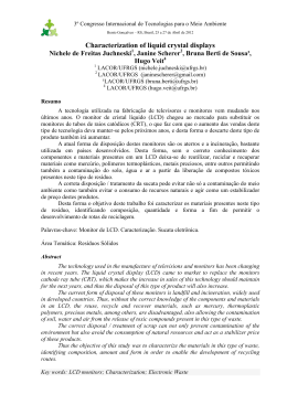
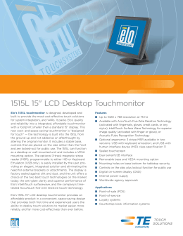
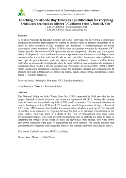
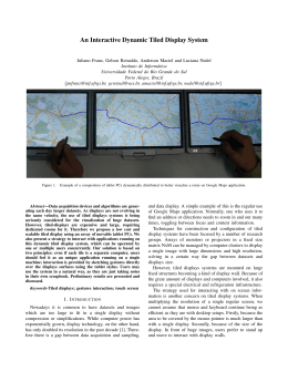
Dispositivos de Saída Gráfica Bacharelado de Informática PUC-Rio Prof. Rodrigo Toledo CLASSIFICAÇÃO • Processamento: – Vetorial – Matricial • Tipo: – Emissora de luz (ex: monitores...) – Não emissora de luz (ex: impressoras...) Matricial x Vetorial Imagem descrita como um bitmap. (entrelaçado ou não) Imagem descrita como uma seqüência de comandos. Obs: Raster-calligraphic (combination of two) DEFINIÇÕES E NOMENCLATURAS • • • • • • • • Pixel (Picture Element) Dot Pitch Resolução (número de linhas e colunas) Resolução de cores Aspect ratio polegadas Persistência (olho humano e equipamentos) Refresh Rate e Frame Rate Refresh Rate e Frame Rate • Refresh rate é a taxa de varredura (ou exposição). Em geral especificada em Hz. • Frame rate é a quantidade de quadros diferentes projetados por segundo (ex: cinema trabalha com 24 frames por segundo) • O olho humano trabalha em uma freqüência aproximada de 48Hz. Refresh Rate e Frame Rate • Projetores antigos de cinema projetavam cada quadro 2 vezes, para se trabalhar na freqüência do olho humano. • Projetores modernos de cinema projetam 3 vezes cada quadro. • Os televisores na Europa trabalham a 50Hz, enquanto no Brasil e nos EUA trabalham a 60Hz. • Por isso, dispositivos que fazem uso da estereoscopia ativa devem trabalhar em freqüências iguais ou superiores a 100Hz. • Cuidado para não confundir com o frame rate para se ter a sensação de tempo real na resposta de um comando (geralmente o mínimo é 12 frames por seg.) PLOTTER • VETORIAL • TINTA Bastante usado na engenharia IMPRESSORAS • Matricial • Jato de Tinta –K – CMYK • Xerox – pb – colorida MONITORES • LCD (displays de cristal líquido) • Plasma (gás) • CRT (tubo de raios catódicos) LCD Displays • Liquid Crystal Display • Organic molecules that remain in crystalline structure without external force, but re-aligns themselves like liquid under external force • So LCDs realigns themselves to EM field and changes their own polarizations Passive LCD • LCD slowly transit between states. • In scanned displays, with a large number of pixels, the percentage of the time that LCDs are excited is very small. • Crystals spend most of their time in intermediate states, being neither "On" or "Off". • These displays are not very sharp and are prone to ghosting. Active Matrix LCD • E field is retained by a capacitor so that the crystal remains in a constant state. • Transistor switches are used to transfer charge into the capacitors during scanning. • The capacitors can hold the charge for significantly longer than the refresh period • Crisp display with no shadows. • More expensive to produce. Plasma Display • Basically fluorescent tubes • High- voltage discharge excites gas mixture (He, Xe), upon relaxation UV light is emitted, UV light excites phosphors •Large view angle •Large format display •Less efficient than CRT, more power •Large pixels: 1mm (0.2 mm for CRT) •Phosphors depletion CRT (tubos de raios catódicos) • Feixes de elétrons são emitidos contra camadas de fósforos, que sensibilizadas emitem radiação eletromagnética na faixa visível do espectro. • Mesmo sistema dos televisores. CRT (tubos de raios catódicos) PROJETORES • CRT • LCD • DLP (ou na verdade, DMD) Projections : The basics CRT LCD and DMD optical path Screen Screen Lens Light source = CRT Image source = CRT 250 - 500 lumens 3200 x 2500 high resolution geometry mature technology flexible positioning photo-realistic Lamp Light source = Lamp Image source = LCD 2000 - 12000 lumens 1280 x 1024 brighter maintenance alignment easy setup pixelization CRT technology CRT technology CRTs Electronics Lenses Screen CRT technology Different tube size 7 inch 8 inch 9 inch 12 inch Scheimpflug correction Projection can’t be done on tilted surface -> focus problem! Scheimpflug correction Required for projection on tilted screens Raster <->Calligraphic Raster image 1280*1024 60Hz Day mode 1280*1024 60Hz 16 ms Pixel remains onscreen for 10 ns Point remains onscreen for 1.5 µs 150 times longer ! Calligraphy Calligraphic Light points Raster Image CRT technology Strengths: Resolution (up to 2500x2000) Good contrast Easy geometrical correction / flexibility Color matching and uniformity Digital soft-edge Unbeatable video and data image quality Life time picture tubes Proven technology Weaknesses: Limited brightness up to 500 ANSI Lumen Needs low ambient lighting conditions Setup time Maintenance Not portable LCD - technology brighter maintenance alignment easy setup Screen Lamp LCD Lens Light source = Lamp Image source = LCD LCD Panels Panel sizes 1.1-1.8 inch (p-Si) 3 inch (a-Si) 6 inch (a-Si) 10 inch (single panel) LCD pros and cons +Well-established technology, stable +Compact, rugged, portable +“zero delay” +UXGA resolution available +Efficient in passive stereo projection (see further) -Response speed limited by LC material some smearing in fast moving images -non-perfect black (contrast ratio 200-300:1, but improving) -pixellization Lens XCube LCD R B G Integrator System Lamp Illumination unit Dichroic Mirror Projection Unit LCOS: Liquid Crystal on Silicon • Essentially: LCD in front of a reflector • Available for microdisplays, projection • D-ILA is JVC’s trade name for LCOS LCOS implementation • LCD on top of CMOS chip that includes transistors and has reflective surface • Aperture ratio is higher than that of LCD (so less pixel visibility) • Efficiency comparable to LCD due to nonperfect reflection • Easy to cool the chip! LCOS addressing • Requires complex optics: side at which chip is illuminated is the same as where the light needs to be extracted from! LCOS integration Complex structure required! LCOS pros and cons + + + + + Higher resolutions possible (up to QXGA) small chip size (1.3” and smaller) good response speed good pixellization (smooth image) higher contrast possible: up to and over 1000:1 reported + chips can be cooled to take high power illumination - alignment hard due to small chip size & high res - difficult to integrate - uniformity? (although seems to be countered now) DMD: another reflective tech Does not require polarized light! Ant leg on DMD chip DMD microstructure Only allows on/off modulation! DMD: grayscale synthesis Frame delay! •1 frame for de-interlacing •1 for sending data through CMOS chip •0-1 frame (depending on gray scale) for gray synthesis 3-chip DMD integration Each chip runs at 10 bits depth, 60 Hz NOTE: 10 bit Linear Gamma equals 8 bit LCD Gamma 3-chip DMD pros & cons +Excellent picture quality (pixels almost invisible) +can take high power illumination +long life (?) +no smearing (but +good intensity uniformity, good color matching +good contrast (400:1) -Expen$ive! -BIG! -PWM artifacts -TI monopoly -Frame delay -Resolution limited to SXGA -Bright edge around chip makes optical blending difficult Single-chip DMD •Sequential illumination of single DMD chip •3 or 4 segment color wheel •chip runs at 8 bit, 240 Hz less bit depth! +Compact -Moving part inside, requires synchronization -Motion artifacts (color breakup) due to color wheel OUTROS (DUET) What is it? IG DUET Active stereo @ 96 - 120 Hz Dual passive stereo SIM 6, 48-60 Hz OUTROS (Soft Edge) Soft Edge: • ESEM: Electonic Soft Edge Modulation • OSEM: Optical Soft Edge Modulation LEFT CHANNEL CENTER CHANNEL RIGHT CHANNEL
Download