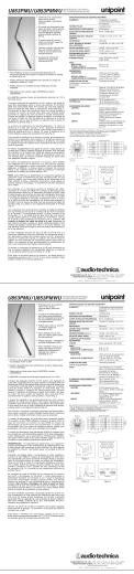
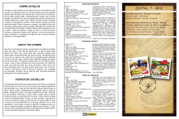
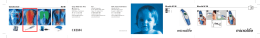
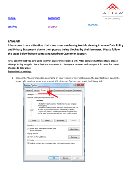
Motors I Automation I Energy I Transmission & Distribution I Coatings Frequency Inverter Convertidor de Frecuencia Inversor de Frequência CFW100 Addendum to the CFW100 User’s Manual Adendo al Manual del Usuario CFW100 Adendo ao Manual do Usuário CFW100 Addendum to the CFW100 User’s Manual Adendo al Manual del Usuario CFW100 Adendo ao Manual do Usuário CFW100 Series/Série: CFW100 English / Español / Português Document/Documento: 10002830877 / 00 Models/Modelos: Frame A, B and C Tam A, B y C Mec A, B e C Date/Fecha/Data: 05/2014 Addendum to the CFW100 User’s Manual English This addendum refers to the RFI filter to reduce electromagnetic interference for the inverters of the CFW100 line, and it must be used together with the CFW100 user manual. 3 INSTALLATION AND CONNECTION 3.3 INSTALLATIONS ACCORDING TO EUROPEAN DIRECTIVE OF ELECTROMAGNETIC COMPATIBILITY The CFW100 inverter series, when properly installed, meet the requirements of the directive of the electromagnetic compatibility. These inverters were developed for professional applications only. Therefore, the emission limits of harmonic currents by the standards EN 61000-3-2 and EN 61000-3-2/A 14. 3.3.1 Conformal Installation 1. Shielded output cables (motor cables) with shield connected at both ends, motor and inverter, by means of a low impedance to high frequency connection. Maximum motor cable length and conduced and radiated emission levels according to Table B3 on page 17. For more information (RFI filter commercial reference, motor cable length and emission levels) refer to the Table B3 on page 17. 2. Shielded control cables, keeping the separation distance from other cables according to Table 3.2 the user's manual. 3.Grounding of the inverter according to instruction of the 3.2.4 Grounding Connections the user's manual. 4.Grounded power supply. 5.The inverter and external filter must be mounted on a common metal plate. 6.The wiring between filter and inverter must be as short as possible. 7. The grounding must be done according to recommendation of the CFW100 user manual. 8.Use short wiring to ground the external filter or inverter. CFW100 | 5 Addendum to the CFW100 User’s Manual English 9.Ground the mounting plate using a flexible braid as short as possible. Flat conductors have lower impedance at high frequencies. 10. Use sleeves for cable conduits whenever possible. 3.3.2 Emission and Immunity Levels Table 3.4: Emission and immunity levels EMC Phenomenon Basic Standard Level Emission: Mains Terminal Disturbance Voltage Frequency Range: 150 kHz to 30 MHz) IEC/EN 61800-3 Electromagnetic Radiation Disturbance” Frequency Range: 30 MHz to 1000 MHz) It depends on the inverter model on the length of the motor cable. Refer to Table B3 on page 17. Immunity: Electrostatic Discharge (ESD) IEC 61000-4-2 4 kV for contact discharge and 8 kV for air discharge 8 kV. Fast Transient-Burst IEC 61000-4-4 2 kV / 5 kHz (coupling capacitor) input cables. 1 kV / 5 kHz control cables and remote HMI cables. 2 kV / 5 kHz (coupling capacitor) motor cables. Conducted Radio-Frequency Common Mode IEC 61000-4-6 0.15 to 80 MHz; 10 V; 80 % AM (1 kHz). Motor, control and HMI cables. Surges IEC 61000-4-5 1.2/50 μs, 8/20 μs. 1 kV line-to-line coupling. 2 kV line-to-ground coupling. Radio-Frequency Electromagnetic Field IEC 61000-4-3 80 to 1000 MHz. 10 V/m. 80 % AM (1 kHz). Definition of Standard IEC/EM 61800-3: “Adjustable Speed Electrical Power Drives Systems” Environments: First Environment: environments that include domestic installations, as well as establishments directly connected without intermediate transformer to a low-voltage power supply network which supplies buildings used for domestic purposes. 6 | CFW100 Addendum to the CFW100 User’s Manual Categories: Category C1: inverters with a voltage rating less than 1000 V and intended for use in the First Environment. Category C2: inverters with a voltage rating less than 1000 V intended for use in the First Environment, not provided with a plug connector or movable installations. They must be installed and commissioned by a professional. NOTE! A professional is a person or organization familiar with the installation and/or commissioning of inverters, including their EMC aspects. Category C3: inverters with a voltage rating less than 1000 V and intended for use in the Second Environment only (not designed for use in the First Environment). 3.3.3 Characteristics of the RFI Filter The CFW100 inverters, when installed with external filter, are used to reduce the disturbance conducted from the inverter to the power line in the high frequency band (>150). It is necessary to meet the maximum levels of conducted emission of electromagnetic compatibility standards, such as EN 61800-3 and EN 55011. For further details, refer to section 3.3 INSTALLATIONS ACCORDING TO EUROPEAN DIRECTIVE OF ELECTROMAGNETIC COMPATIBILITY on page 5 in this addendum. For further information about the RFI filter model, refer to Appendix B on page 17 Figure B4 on page 18. The figure below demonstrate the connection of the filters to the inverter: CFW100 | 7 English Second Environment: includes all establishments other than those directly connected to a lowvoltage power supply network that supplies buildings used for domestic purposes. Addendum to the CFW100 User’s Manual Signal and control wiring English External input RFI filter Transformer L1/L L1 Power supply XC1 1...5 L1/L U CFW100 V L2/N L2 PE PE PE L2/N W PE PE Motor Metal panel (when necessary) Grounding rod Protective ground Figure 7.1: Connection of the RFI filter - general conditions 8 TECHNICAL SPECIFICATIONS 8.2.1 Codes and Standards Table 8.2: Codes and standards ELECTROMAGNETIC COMPATIBILITY (EMC) STANDARDS EN 61800-3 - Adjustable speed electrical power drive systems - Part 3: EMC product standard including specific test methods. EN 55011 - Limits and methods of measurement of radio disturbance characteristics of industrial, scientific and medical (ISM) radio-frequency equipment. CISPR 11 - Industrial, scientific and medical (ISM) radio-frequency equipment – Electromagnetic disturbance characteristics - Limits and methods of measurement. EN 61000-4-2 - Electromagnetic compatibility (EMC) - Part 4: Testing and measurement techniques - Section 2: Electrostatic discharge immunity test. EN 61000-4-3 - Electromagnetic compatibility (EMC) - Part 4: Testing and measurement techniques - Section 3: Radiated, radio-frequency, electromagnetic field immunity test. EN 61000-4-4 - Electromagnetic compatibility (EMC) - Part 4: Testing and measurement techniques - Section 4: Electrical fast transient/burst immunity test. EN 61000-4-5 - Electromagnetic compatibility (EMC) - Part 4: Testing and measurement techniques - Section 5: Surge immunity test. EN 61000-4-6 - Electromagnetic compatibility (EMC)- Part 4: Testing and measurement techniques - Section 6: Immunity to conducted disturbances, induced by radiofrequency fields. 8 | CFW100 Adendo al Manual del Usuario CFW100 Este adendo se refiere al filtro RFI para los convertidores de la línea CFW100, para reducción de la interferencia electromagnética, y debe ser utilizado con el manual del usuario CFW100. 3 INSTALACIÓN Y CONEXIÓN 3.3 INSTALACIONES DE ACUERDO CON LA DIRECTIVA EUROPEA DE COMPATIBILIDAD ELECTROMAGNÉTICA La serie de inversores CFW100, cuando son correctamente instalados, cumplen los requisitos de la directiva de compatibilidad electromagnética. Estos convertidores fueron desarrollados solamente para aplicaciones profesionales. Por eso no se aplican los límites de emisiones de corrientes harmónicas definidas por las normas EN 61000-3-2 y EN 61000-3-2/A 14. 1.Cables de salida (cables del motor) blindados y con el blindaje conectado en ambos lados, motor y convertidor con conexión de baja impedancia para alta frecuencia. Longitud máxima del cable del motor y niveles de emisión conducida y radiada según la Tabla B3 en la página 17. Para más informaciones (referencia comercial del filtro RFI, longitud del cable del motor y niveles de emisión) consulte la Tabla B3 en la página 17. 2.Cables de control blindados y mantenga la separación de los demás según la Tabla 3.2 del manual del usuário. 3.Aterramiento del convertidor según instrucciones del ítem 3.2.4 Conexiones de Aterramiento del manual del usuario. 4.Red de alimentación aterrada. 5.El convertidor y el filtro externo deben ser montados próximos uno del otro, sobre una chapa metálica común. 6.El cableado entre filtro y convertidor debe ser lo más corto posible. 7.La puesta a tierra debe ser hecha conforme es recomendado en el manual del usuario del CFW100. CFW100 | 9 Español 3.3.1 Instalación Conforme Adendo al Manual del Usuario CFW100 8.Use cableado corto para la puesta a tierra del filtro externo o del convertidor. 9.Ponga a tierra la chapa de montaje utilizando un cable lo más corto posible. Conductores planos tienen impedancia menor a altas frecuencias. 10. Use guantes para conduítes siempre que sea posible. 3.3.2 Niveles de Emisión y Inmunidad Atendida Tabla 3.4: Niveles de emisión y inmunidad atendidos Fenómeno de EMC Norma Básica Nível Emisión: Emisión Conducida (“Mains Terminal Disturbance Voltage” Rango de Frecuencia: 150 kHz a 30 MHz) Español Emisión Radiada (“Electromagnetic Radiation Disturbance” Rango de Frecuencia: 30 MHz a 1000 MHz) IEC/EN 61800-3 Depende del modelo del convertidor y de la longitud del cable del motor. Consulte la Tabla B3 en la página 17. lnmunidad: Descarga Electrostática (ESD) IEC 61000-4-2 4 kV descarga por contacto y 8 kV descargapor el aire. Transientes Rápidos (“Fast Transient-Burst”) IEC 61000-4-4 2 kV / 5 kHz (acoplador capacitivo) cables de entrada. 1 kV / 5 kHz cables de control y de la HMl remota. 2 kV / 5 kHz (acoplador capacitivo) cable del motor. lnmunidad Conducida (“Conducted Radio- Frequency Common Mode”) IEC 61000-4-6 0.15 a 80 MHz; 10 V; 80 % AM (1 kHz). Cables del motor, de control y de la HMl remota. Sobretensiones IEC 61000-4-5 1.2/50 μs, 8/20 μs. 1 kV acoplamiento línea-línea. 2 kV acoplamiento línea-tierra. Campo Electromagnético de Radiofrecuencia IEC 61000-4-3 80 a 1000 MHz. 10 V/m. 80 % AM (1 kHz). Definiciones de la Norma IEC/EM 61800-3: “Adjustable Speed Electrical Power Drives Systems” 10 | CFW100 Adendo al Manual del Usuario CFW100 A mbientes: Primer Ambiente (“First Environment”): ambientes que incluyen instalaciones domésticas, como establecimientos conectados sin transformadores intermediarios a la red de baja tensión, la cual alimenta instalaciones de uso doméstico. Segundo Ambiente (“Second Environment”): ambientes que incluyen todos los establecimientos que no están conectados directamente a la red de baja tensión, la cual alimenta instalaciones de uso doméstico. Categorías: Categoría C1: convertidores con tensiones menores que 1000 V, para uso en el “Primer Ambiente”. ¡NOTA! Se entiende por profesional a una persona o organización con conocimiento en instalación y/o puesta en funcionamiento de los inversores, incluyendo sus aspectos de EMC. Categoria C3: convertidores con tensiones menores que 1000 V, desarrollados para uso en el “Segundo Ambiente” y no proyectados para uso en el “Primer Ambiente”. 3.3.3 Características del Filtro Supresor de RFI Los convertidores CFW100 cuando son montados con filtro externo, son utilizados para reducir la perturbación conducida del convertidor hacia la red eléctrica en el rango de altas frecuencias (>150 kHz). Para alcanzar los niveles máximos de emisión conducida, se hace necesario el cumplimiento de normas de compatibilidad electromagnética como la EN 61800-3 y EN 55011. Para más detalles consulte la sección 3.3 INSTALACIONES DE ACUERDO CON LA DIRECTIVA EUROPEA DE COMPATIBILIDAD ELECTROMAGNÉTICA en la página 9 de este anexo. Para informaciones sobre el modelo del filtro RFI consulte el Anexo B en la página 17 Figura B4 en la página 18. CFW100 | 11 Español Categoría C2: convertidores con tensiones menores que 1000 V, que no son provistos de plugs o instalaciones móviles y, cuando sean utilizados en el “Primer Ambiente”, deberán ser instalados y puestos en funcionamiento por un profesional. Adendo al Manual del Usuario CFW100 La figura de abajo muestra la conexión de los filtros al convertidor: Cableado de señal y control Filtro de RFI de entrada externo Transformador L1/L L1 XC1 1...5 L1/L U CFW100 V Alimentación L2/N L2 PE PE PE Varilla de puesta a tierra L2/N W PE PE Motor Tablero metálico (cuando es necesario) Tierra de protección Figura 7.1: Conexión del filtro supresor de RFI - condición general Español 8 ESPECIFICACIONES TÉCNICAS 8.2.1 Normas Consideradas Tabla 8.2: Normas consideradas NORMAS DE EN 61800-3 - Adjustable speed electrical power drive systems - Part 3: EMC product standard including specific test methods. COMPATIBILIDAD ELECTROMAGNÉTICA EN 55011 - Limits and methods of measurement of radio disturbance characteristics of industrial, scientific and medical (ISM) radio-frequency equipment. CISPR 11 - Industrial, scientific and medical (ISM) radio-frequency equipment – Electromagnetic disturbance characteristics - Limits and methods of measurement. EN 61000-4-2 - Electromagnetic compatibility (EMC) - Part 4: Testing and measurement techniques - Section 2: Electrostatic discharge immunity test. EN 61000-4-3 - Electromagnetic compatibility (EMC) - Part 4: Testing and measurement techniques - Section 3: Radiated, radio-frequency, electromagnetic field immunity test. EN 61000-4-4 - Electromagnetic compatibility (EMC) - Part 4: Testing and measurement techniques - Section 4: Electrical fast transient/burst immunity test. EN 61000-4-5 - Electromagnetic compatibility (EMC) - Part 4: Testing and measurement techniques - Section 5: Surge immunity test. EN 61000-4-6 - Electromagnetic compatibility (EMC)- Part 4: Testing and measurement techniques - Section 6: Immunity to conducted disturbances, induced by radiofrequency fields. 12 | CFW100 Adendo ao Manual do Usuário CFW100 Este adendo refere-se ao filtro RFI para os inversores da linha CFW100, para redução da interferência eletromagnética, e deve ser utilizado juntamente com o manual do usuário CFW100. 3 INSTALAÇÃO E CONEXÃO 3.3 INSTALAÇÕES DE ACORDO COM A DIRETIVA EUROPEIA DE COMPATIBILIDADE ELETROMAGNÉTICA A série de inversores CFW100, quando corretamente instalados, atendem os requisitos da diretiva de compatibilidade eletromagnética. Estes inversores foram desenvolvidos apenas para aplicações profissionais. Por isso não se aplicam os limites de emissões de correntes harmônicas definidas pelas normas EN 61000-3-2 e EN 61000-3-2/A 14. 3.3.1 Instalação Conforme 1.Cabos de saída (cabos do motor) blindados e com a blindagem conectada em ambos os lados, motor e inversor com conexão de baixa impedância para alta frequência. Comprimento máximo do cabo do motor e níveis de emissão conduzida e radiada conforme a Tabela B3 na página 17. Para mais informações (referência comercial do filtro RFI, comprimento do cabo do motor e níveis de emissão) consulte a Tabela B3 na página 17. 2.Cabos de controle blindados e mantenha a separação dos demais conforme Tabela 3.2 do manual do usuário. 3.Aterramento do inversor conforme instruções do item 3.2.4 Conexões de Aterramento do manual do usuário. 4.Rede de alimentação aterrada. 6.A fiação entre filtro e inversor deve ser o mais curta possível. 7. O aterramento deve ser feito conforme recomendado no manual do usuário do CFW100. 8.Use fiação curta para aterramento do filtro externo ou inversor. CFW100 | 13 Português 5. O inversor e o filtro externo devem ser montados próximos sobre uma chapa metálica comum. Adendo ao Manual do Usuário CFW100 9.Aterre a chapa de montagem utilizando uma cordoalha, o mais curto possível. Condutores planos têm impedância menor em altas frequências. 10. Use luvas para conduítes sempre que possível. 3.3.2 Níveis de Emissão e Imunidade Atendida Tabela 3.4: Níveis de emissão e imunidade atendidos Fenómeno de EMC Norma Básica Nível Emissão: Emissão Conduzida (“Mains Terminal Disturbance Voltage” Faixa de Frequência: 150 kHz a 30 MHz) IEC/EN 61800-3 Depende do modelo do inversor e do comprimento do cabo do motor. Consulte a Tabela B3 na página 17. Descarga Eletrostática (ESD) IEC 61000-4-2 4 kV descarga por contato e 8 kV descarga pelo ar. Transientes Rápidos (“Fast Transient-Burst”) IEC 61000-4-4 2 kV / 5 kHz (acoplador capacitivo) cabos de entrada. 1 kV / 5 kHz cabos de controle e da HMI remota. 2 kV / 5 kHz (acoplador capacitivo) cabo do motor. Imunidade Conduzida (“Conducted Radio-Frequency Common Mode”) IEC 61000-4-6 0.15 a 80 MHz; 10 V; 80 % AM (1 kHz). Cabos do motor, de controle e da HMI remota. Surtos IEC 61000-4-5 1.2/50 μs, 8/20 μs. 1 kV acoplamento linha-linha. 2 kV acoplamento linha-terra. Campo Eletromagnético de Radiofrequência IEC 61000-4-3 80 a 1000 MHz. 10 V/m. 80 % AM (1 kHz). Emissão Radiada (“Electromagnetic Radiation Disturbance” Faixa de Frequência: 30 MHz a 1000 MHz) Imunidade: Português Definições da Norma IEC/EM 61800-3: “Adjustable Speed Electrical Power Drives Systems” 14 | CFW100 Adendo ao Manual do Usuário CFW100 A mbientes: Primeiro Ambiente (“First Environment”): ambientes que incluem instalações domésticas, como estabelecimentos conectados sem transformadores intermediários à rede de baixa tensão, a qual alimenta instalações de uso doméstico. Segundo Ambiente (“Second Environment”): ambientes que incluem todos os estabelecimentos que não estão conectados diretamente à rede baixa tensão, a qual alimenta instalações de uso doméstico. Categorias: Categoria C1: inversores com tensões menores que 1000 V, para uso no “Primeiro Ambiente”. Categoria C2: inversores com tensões menores que 1000 V, que não são providos de plugs ou instalações móveis e, quando forem utilizados no “Primeiro Ambiente”, deverão ser instalados e colocados em funcionamento por profissional. NOTA! Por profissional entende-se uma pessoa ou organização com conhecimento em instalação e/ou colocação em funcionamento dos inversores, incluindo os seus aspectos de EMC. Categoria C3: inversores com tensões menores que 1000 V, desenvolvidos para uso no “Segundo Ambiente” e não projetados para uso no “Primeiro Ambiente”. 3.3.3 Características do Filtro Supressor de RFI Para mais detalhes, consulte a seção 3.3 INSTALAÇÕES DE ACORDO COM A DIRETIVA EUROPEIA DE COMPATIBILIDADE ELETROMAGNÉTICA na página 13 deste adendo. Para informações sobre o modelo do filtro RFI consulte o Anexo B na página 17 Figura B4 na página 18. CFW100 | 15 Português Os inversores CFW100 quando montados com filtro externo, são utilizados para reduzir a perturbação conduzida do inversor para a rede elétrica na faixa de altas frequências (>150 kHz). Necessário para o atendimento dos níveis máximos de emissão conduzida de normas de compatibilidade eletromagnética como a EN 61800-3 e EN 55011. Adendo ao Manual do Usuário CFW100 A figura abaixo demonstra a conexão dos filtros ao inversor: Fiação de sinal e controle Filtro de RFI de entrada externo Transformador L1/L L1 XC1 1...5 L1/L U CFW100 V Alimentação L2/N L2 PE PE PE Haste de aterramento L2/N W PE PE Motor Painel metálico (quando necessário) Terra de proteção Figura 7.1: Conexão do filtro supressor de RFI - condição geral 8 ESPECIFICAÇÕES TÉCNICAS 8.2.1 Normas Consideradas Tabela 8.2: Normas consideradas NORMAS DE COMPATIBILIDADE ELETROMAGNÉTICA EN 61800-3 - Adjustable speed electrical power drive systems - Part 3: EMC product standard including specific test methods. EN 55011 - Limits and methods of measurement of radio disturbance characteristics of industrial, scientific and medical (ISM) radio-frequency equipment. CISPR 11 - Industrial, scientific and medical (ISM) radio-frequency equipment – Electromagnetic disturbance characteristics - Limits and methods of measurement. EN 61000-4-2 - Electromagnetic compatibility (EMC) - Part 4: Testing and measurement techniques - Section 2: Electrostatic discharge immunity test. EN 61000-4-3 - Electromagnetic compatibility (EMC) - Part 4: Testing and measurement techniques - Section 3: Radiated, radio-frequency, electromagnetic field immunity test. EN 61000-4-4 - Electromagnetic compatibility (EMC) - Part 4: Testing and measurement techniques - Section 4: Electrical fast transient/burst immunity test. Português EN 61000-4-5 - Electromagnetic compatibility (EMC) - Part 4: Testing and measurement techniques - Section 5: Surge immunity test. EN 61000-4-6 - Electromagnetic compatibility (EMC)- Part 4: Testing and measurement techniques - Section 6: Immunity to conducted disturbances, induced by radiofrequency fields. 16 | CFW100 Appendix B / Anexo B APPENDIX B ANEXO B Table B3: Conducted and radiated emission levels, and additional information Tabla B3: Niveles de emisión conducida y irradiada y informaciones adicionales 1 CFW100A01P6S220 2 CFW100B02P6S220 3 CFW100C04P2S220 Radiated Emission Emisión Radiada Emissão Radiada Conducted Emission – Maximum Motor Cable Length Emisión Conducida – Longitud Maxima del Cable del Motor Emissão Conduzida – Comprimento Máximo do Cabo do Motor Inverter Model Modelo del Convertidor de Frecuencia Modelo do Inversor Tabela B3: Níveis de emissão conduzida e radiada e informações adicionais Category C3 Categoría C3 Categoria C3 Category C2 Categoría C2 Categoria C2 Category Categoría Categoria 10 m 1m C3 Notes: (1) The switching frequency is 5 kHz. (2) For Electromagnetic Radiation Disturbance consider the mounting of a metal panel. For model 3, use choke (T60006-L2016-W403 – VACUUMSCHMELZE) for shielded cable 10 m, or 1 m without choke. Notas: (1) La frecuencia de conmutación es de 5 kHz. (2) Para Emisión Radiada considerar montaje en tablero metálico. En el modelo 3 utilizar choke (T60006-L2016-W403 – VACUUMSCHMELZE) para cable blindado 10 m, o 1 m sin choke. Notas: (1) A frequência de chaveamento é de 5 kHz. (2) Para Emissão Radiada considerar montagem em painel metálico. No modelo 3 utilizar choke (T60006-L2016-W403 – VACUUMSCHMELZE) para cabo blindado 10 m, ou 1 m sem choke. CFW100 | 17 Appendix B / Anexo B Figure B4: Model of the RFI Filter B84142A0020R000 (20 A) EPCOS Figura B4: Modelo del Filtro Supresor RFI B84142A0020R000 (20 A) EPCOS Figura B4: Modelo do Filtro Supressor RFI B84142A0020R000 (20 A) EPCOS 50.8±0.3 35±1 6.3 35±1 84 20 11 99 121±1 16±1 PE M5 x 20 24±1 Terminals 4 mm 2 Terminales 4 mm 2 Terminais 4 mm 2 0.8±0.1 4.3±0.1 +0.1 95.2 -0.5 105 Terminals 4 mm 2 Terminales 4 mm 2 Terminais 4 mm 2 24±1 +1 68 -0.6 Note: Dimensions of figures in mm. Obs.: Medidas de las figuras en mm. Obs.: Medidas das figuras em mm. Standard model: B84142-A20-R Voltage: 250 V, 50/60 Hz Current: 20 A Weight: 1 Kg 18 | CFW100 Modelo estándar: B84142-A20-R Tensión: 250 V, 50/60 Hz Corriente: 20 A Peso: 1 Kg Modelo standard: B84142-A20-R Tensão: 250 V, 50/60 Hz Corrente: 20 A Peso: 1 Kg WEG Drives & Controls - Automação LTDA. Jaraguá do Sul - SC - Brazil Phone 55 (47) 3276-4000 - Fax 55 (47) 3276-4020 São Paulo - SP - Brazil Phone 55 (11) 5053-2300 - Fax 55 (11) 5052-4212 [email protected] www.weg.net 12783295
Download