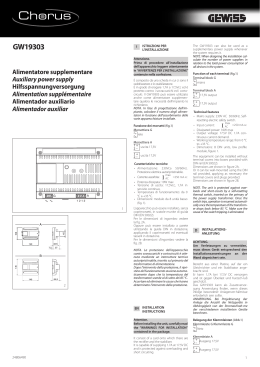
Libretto di Istruzioni
Instructions Manual
Manuel d’Instructions
Bedienungsanleitung
Gebruiksaanwijzing
Manual de Instruções
Руководство по эксплуатации
INDICE
IT
CONSIGLI E SUGGERIMENTI.............................................................................................................................................. 4
CARATTERISTICHE.............................................................................................................................................................. 5
INSTALLAZIONE ................................................................................................................................................................... 6
USO........................................................................................................................................................................................ 8
MANUTENZIONE ................................................................................................................................................................ 10
INDEX
EN
RECOMMENDATIONS AND SUGGESTIONS ................................................................................................................... 11
CHARACTERISTICS ........................................................................................................................................................... 12
INSTALLATION.................................................................................................................................................................... 13
USE ...................................................................................................................................................................................... 15
MAINTENANCE ................................................................................................................................................................... 17
SOMMAIRE
FR
CONSEILS ET SUGGESTIONS.......................................................................................................................................... 18
CARACTERISTIQUES......................................................................................................................................................... 19
INSTALLATION.................................................................................................................................................................... 20
UTILISATION ....................................................................................................................................................................... 22
ENTRETIEN......................................................................................................................................................................... 24
INHALTSVERZEICHNIS
DE
EMPFEHLUNGEN UND HINWEISE ................................................................................................................................... 25
CHARAKTERISTIKEN ......................................................................................................................................................... 26
MONTAGE ........................................................................................................................................................................... 27
BEDIENUNG........................................................................................................................................................................ 29
WARTUNG........................................................................................................................................................................... 31
INHOUDSOPGAVE
NL
ADVIEZEN EN SUGGESTIES............................................................................................................................................. 32
EIGENSCHAPPEN .............................................................................................................................................................. 33
INSTALLATIE....................................................................................................................................................................... 34
GEBRUIK ............................................................................................................................................................................. 36
ONDERHOUD...................................................................................................................................................................... 38
ÍNDICE
PT
CONSELHOS E SUGESTÕES............................................................................................................................................ 39
CARACTERÍSTICAS ........................................................................................................................................................... 40
INSTALAÇÃO....................................................................................................................................................................... 41
UTILIZAÇÃO ........................................................................................................................................................................ 43
MANUTENÇÃO.................................................................................................................................................................... 45
2
2
УКАЗАТЕЛЬ
RU
СОВЕТЫ И РЕКОМЕНДАЦИИ .......................................................................................................................................... 46
ХАРАКТЕРИСТИКИ............................................................................................................................................................ 47
УСТАНОВКА........................................................................................................................................................................ 48
ЭКСПЛУАТАЦИЯ................................................................................................................................................................ 50
УХОД.................................................................................................................................................................................... 52
3
3
CONSIGLI E SUGGERIMENTI
Questo libretto di istruzioni per l'uso è previsto per più versioni dell' apparecchio.
É possibile che siano descritti singoli particolari della dotazione, che non riguardano il Vostro apparecchio.
INSTALLAZIONE
• Il produttore declina qualsiasi responsabilità per danni dovuti ad installazione non
corretta o non conforme alle regole dell’arte.
• La distanza minima di sicurezza tra il Piano di cottura e la Cappa deve essere di
650 mm, (alcuni modelli possono essere installati ad un’altezza inferiore, fare riferimento ai paragrafi ingombro e installazione).
• Verificare che la tensione di rete corrisponda a quella riportata nella targhetta
posta all’interno della Cappa.
• Per Apparecchi in Classe Ia accertarsi che l’impianto elettrico domestico garantisca un corretto scarico a terra.
• Collegare la Cappa all’uscita dell’aria aspirata con tubazione di diametro pari o
superiore a 120 mm. Il percorso della tubazione deve essere il più breve possibile.
• Non collegare la Cappa a condotti di scarico dei fumi prodotti da combustione
(caldaie, caminetti, ecc.).
• Nel caso in cui nella stanza vengano utilizzati sia la Cappa che apparecchi non
azionati da energia elettrica (ad esempio apparecchi utilizzatori di gas), si deve
provvedere ad una aerazione sufficiente dell’ambiente. Se la cucina ne fosse
sprovvista, praticare un’apertura che comunichi con l’esterno, per garantire il richiamo d’aria pulita.
USO
• La Cappa è stata progettata esclusivamente per uso domestico, per abbattere gli
odori della cucina.
• Non fare mai uso improprio della Cappa.
• Non lasciare fiamme libere a forte intensità sotto la Cappa in funzione.
• Regolare sempre le fiamme in modo da evitare una evidente fuoriuscita laterale
delle stesse rispetto al fondo delle pentole.
• Controllare le friggitrici durante l’uso: l’olio surriscaldato potrebbe infiammarsi.
• Non preparare alimenti flambè sotto la cappa da cucina; pericolo d'incendio.
• Questo apparecchio non deve essere utilizzato da persone (bambini inclusi) con
ridotte capacità psichiche, sensoriali o mentali, oppure da persone senza esperienza e conoscenza, a meno che non siano controllati o istruiti all’uso
dell’apparecchio da persone responsabili della loro sicurezza.
• I bambini devono essere supervisionati per assicurarsi che non giochino con
l’apparecchio.
650 mm min.
MANUTENZIONE
• Prima di procedere a qualsiasi operazione di manutenzione, disinserire la Cappa
togliendo la spina elettrica o spegnendo l’interruttore generale.
• Effettuare una scrupolosa e tempestiva manutenzione dei Filtri secondo gli intervalli consigliati (Rischio di incendio).
• Per la pulizia delle superfici della Cappa è sufficiente utilizzare un panno umido e
detersivo liquido neutro.
Il simbolo
sul prodotto o sulla confezione indica che il prodotto non deve essere considerato
come un normale rifiuto domestico, ma deve essere portato nel punto di raccolta appropriato per
il riciclaggio di apparecchiature elettriche ed elettroniche. Provvedendo a smaltire questo prodotto in modo appropriato, si contribuisce a evitare potenziali conseguenze negative per l’ambiente
e per la salute, che potrebbero derivare da uno smaltimento inadeguato del prodotto. Per informazioni più dettagliate sul riciclaggio di questo prodotto, contattare l’ufficio comunale, il servizio
locale di smaltimento rifiuti o il negozio in cui è stato acquistato il prodotto.
IT
4
4
CARATTERISTICHE
Ingombro
Min.
Min.
650mm 650mm
12e
Componenti
Rif.
1
8
9
10a
10a
10b
20
Q.tà Componenti di Prodotto
1 Corpo Cappa completo di: Comandi, Luce, Gruppo
Ventilatore, Filtri
1 Griglia direzionata uscita aria
1 Flangia ø 150
1 Flangia ø 120
1 Flangia con Valvola ø 120
1 Anello di Maggiorazione ø 120-125 mm
1 Profilo chiusura
Rif.
12a
12e
12f
Q.tà
4
2
5
Componenti di Installazione
Viti 3,5 x 16
Viti 2,9 x 12,7
Viti 2,9 x 9,5
8
9
10b
10a
1
12a
20
12f
Q.tà Documentazione
1 Libretto Istruzioni
IT
5
5
INSTALLAZIONE
Foratura Piano di supporto e Montaggio Cappa
• La Cappa può essere installata direttamente
sul piano inferiore dei Pensili (650 mm min.
dal Piano di Cottura) con i Supporti laterali a
scatto.
• Praticare un incasso sul piano inferiore del
Pensile, come indicato. (fig.1)
• Inserire la flangia nel foro superiore di scarico. (fig.2)
• Avvitare il profilo di chiusura 20 alla parte
posteriore della cappa utilizzando le viti 12f
(2,9 x 9,5) in dotazione. (fig.3)
• Aprire il carrello aspirante.
• Togliere i Filtri Antigrasso uno alla volta,
agendo sugli appositi agganci.
• Richiudere il carrello aspirante.
• Inserire la Cappa fino ad agganciare i Supporti laterali a scatto. (fig.4)
• Aprire il carrello aspirante.
• Bloccare definitivamente serrando le Viti Vf
dal sotto della Cappa. (fig.4)
• Se è necessario effettuare degli aggiustamenti dell'intero corpo portafiltri, operare
come segue:
• Allentare le quattro viti di regolazione Vr
e richiudere il carrello. (fig.5)
• Traslare l'intero corpo portafiltri fino ad
ottenere l'allineamento desiderato con il
pensile. (fig.6)
• Sempre mantenendo fermo il corpo cappa
estrarre il carrello e serrare le viti di regolazione Vr. (fig.5)
• Ora è possibile fissare definitivamente la
cappa al pensile usando le viti 12a (3,5 x
16) in dotazione. (fig.7)
• Rimontare i Filtri antigrasso.
• Richiudere il carrello aspirante.
1
2
10b
10a
9
162
523
10a
ø120
3
4
Vr
5
6
12a
7
IT
6
6
Connessioni
USCITA ARIA VERSIONE ASPIRANTE
Per installazione in Versione Aspirante collegare la
Cappa alla tubazione di uscita per mezzo di un tubo
rigido o flessibile dello stesso diametro della flangia
precedentemente installata
• Fissare il tubo con adeguate fascette stringitubo. Il
materiale occorrente non è in dotazione.
• Togliere eventuali Filtri Antiodore al Carbone attivo.
USCITA ARIA VERSIONE FILTRANTE
12e
• Praticare un foro ø 125 mm sull’eventuale Mensola
soprastante la Cappa.
• Inserire la Flangia 10a sull’uscita del Corpo Cappa.
• Collegare la Flangia al foro di uscita sulla Mensola
soprastante la Cappa con un tubo rigido o flessibile di
ø120 mm.
• Fissare il tubo con adeguate fascette stringitubo. Il
materiale occorrente non è in dotazione.
• Fissare la Griglia direzionata 8 sull’uscita con 2 Viti
12e (2,9 x 12,7) in dotazione.
• Assicurarsi della presenza dei Filtri antiodore al Carbone attivo.
8
CONNESSIONE ELETTRICA
• Collegare la Cappa all’Alimentazione di Rete interponendo un Interruttore bipolare con apertura dei contatti di almeno 3 mm.
IT
7
7
USO
L
M
Le varie funzioni vengono attivate automaticamente con l’estrazione del carrello. Per spegnere
le funzioni impostate sarà sufficiente richiudere il carrello.
TASTO
FUNZIONE
L
Luci
Accende e spegne l’Impianto di Illuminazione.
M
Motore
Accende e spegne il motore Aspirazione.
1. Velocità minima, adatta ad un ricambio d’aria continuo particolarmente
silenzioso,in presenza di pochi vapori di cottura.
2. Velocità media, adatta alla maggior parte delle condizioni d’uso, dato
l’ottimo rapporto tra portata d’aria trattata e livello sonoro.
3. Velocità massima, adatta a fronteggiare grandi emissioni di vapore di
cottura,anche per tempi prolungati.
IT
8
8
L
M
Le varie funzioni vengono attivate automaticamente con l’estrazione del carrello. Per spegnere
le funzioni impostate sarà sufficiente richiudere il carrello.
TASTO
FUNZIONE
L
Luci
Accende e spegne l’Impianto di Illuminazione.
M
Motore
Accende e spegne il motore Aspirazione.
1. Velocità minima, adatta ad un ricambio d’aria continuo particolarmente
silenzioso,in presenza di pochi vapori di cottura.
2. Velocità media, adatta alla maggior parte delle condizioni d’uso, dato
l’ottimo rapporto tra portata d’aria trattata e livello sonoro.
3. Velocità massima, adatta a fronteggiare grandi emissioni di vapore di
cottura,anche per tempi prolungati.
i.
IT
Velocità intensiva, adatta a fronteggiare le massime emissioni di fumi di
cottura.
9
9
MANUTENZIONE
Filtri antigrasso
PULIZIA FILTRI ANTIGRASSO METALLICI AUTOPORTANTI
• Sono lavabili anche in lavastoviglie, e necessitano di essere
lavati ogni 2 mesi circa di utilizzo o più frequentemente, per un
uso particolarmente intenso.
• Estrarre il carrello aspirante.
• Togliere i Filtri uno alla volta, agendo sugli appositi agganci.
• Lavare i Filtri evitando di piegarli, e lasciarli asciugare prima
di rimontarli. (Un’eventuale cambiamento del colore della superficie del filtro, che potrebbe verificarsi nel tempo, non pregiudica assolutamente l’efficienza dello stesso.)
• Rimontarli facendo attenzione a mantenere la maniglia verso la
parte visibile esterna.
• Chiudere il carrello aspirante.
Filtri antiodore (Versione Filtrante)
SOSTITUZIONE
Attenzione: Spegnere le luci ed attendere il raffreddamento delle
lampade prima di effettuare la sostituzione del filtro antiodore.
• Non sono lavabili né rigenerabili, vanno sostituiti ogni 4 mesi
circa di utilizzo o più frequentemente, per un uso particolarmente intenso.
• Estrarre il carrello aspirante.
• Togliere i Filtri Antigrasso
• Rimuovere il Filtro antiodore al Carbone attivo saturo, agendo
sugli appositi agganci.
• Rimontare i Filtri antigrasso.
• Richiudere il carrello aspirante.
Illuminazione
SOSTITUZIONE LAMPADE
Lampade fluorescenti da 9 W.
• Togliere i terminali metallici che fissano la plafoniera in vetro.
• Far scorrere la plafoniera in vetro verso un lato, fino a liberare
l’estremità opposta. Abbassare leggermente l’estremità libera e
farlo scorrere fino a liberarlo totalmente.
• Sostituire la lampada con una nuova di uguali caratteristiche.
• Rimontare la plafoniera in vetro in sequenza inversa.
IT
1
10
RECOMMENDATIONS AND SUGGESTIONS
The Instructions for Use apply to several versions of this appliance. Accordingly, you may find descriptions of individual features that do not apply to
your specific appliance.
INSTALLATION
• The manufacturer will not be held liable for any damages resulting from incorrect or improper installation.
• The minimum safety distance between the cooker top and the extractor
hood is 650 mm (some models can be installed at a lower height, please refer to the paragraphs on working dimensions and installation).
• Check that the mains voltage corresponds to that indicated on the rating
plate fixed to the inside of the hood.
• For Class I appliances, check that the domestic power supply guarantees
adequate earthing.
Connect the extractor to the exhaust flue through a pipe of minimum diameter 120 mm. The route of the flue must be as short as possible.
• Do not connect the extractor hood to exhaust ducts carrying combustion
fumes (boilers, fireplaces, etc.).
• If the extractor is used in conjunction with non-electrical appliances (e.g. gas
burning appliances), a sufficient degree of aeration must be guaranteed in
the room in order to prevent the backflow of exhaust gas. The kitchen must
have an opening communicating directly with the open air in order to guarantee the entry of clean air.
USE
• The extractor hood has been designed exclusively for domestic use to eliminate kitchen smells.
• Never use the hood for purposes other than for which it has been designed.
• Never leave high naked flames under the hood when it is in operation.
• Adjust the flame intensity to direct it onto the bottom of the pan only, making
sure that it does not engulf the sides.
• Deep fat fryers must be continuously monitored during use: overheated oil
can burst into flames.
• Do not flambè under the range hood; risk of fire
• This appliance is not intended for use by persons (including children) with
reduced physical, sensory or mental capabilities, or lack of experience and
knowledge, unless they have been given supervision or instruction concerning use of the appliance by a person responsible for their safety.
• Children should be supervised to ensure that they do not play with the appliance.
650 mm min.
MAINTENANCE
• Switch off or unplug the appliance from the mains supply before carrying out
any maintenance work.
• Clean and/or replace the Filters after the specified time period (Fire hazard).
• Clean the hood using a damp cloth and a neutral liquid detergent.
The symbol
on the product or on its packaging indicates that this product may not be treated
as household waste. Instead it shall be handed over to the applicable collection point for the
recycling of electrical and electronic equipment. By ensuring this product is disposed of correctly,
you will help prevent potential negative consequences for the environment and human health,
which could otherwise be caused by inappropriate waste handling of this product. For more
detailed information about recycling of this product, please contact your local city office, your
household waste disposal service or the shop where you purchased the product.
EN
1
11
CHARACTERISTICS
Dimensions
Min.
Min.
650mm 650mm
Components
Ref.
1
8
9
10a
10a
10b
20
Q.ty Product Components
1 Hood Body, complete with: Controls, Light, Blower,
Filters
1 Directional Air Outlet grille
1 Flange ø 150 mm
1 Flange ø 120 mm
1 Dumper ø 120 mm
1 Adapting ring ø 120-125 mm
1 Closing element
Ref.
12a
12e
12f
Q.ty
4
2
5
Installation Components
Screws 3,5 x 16
Screws 2,9 x 12,7
Screws 2,9 x 9,5
12e
8
9
10b
10a
1
12a
20
12f
Q.ty Documentation
1 Instruction Manual
EN
1
12
INSTALLATION
Drilling the Support surface and Fitting the Hood
• The Hood can be fitted directly on the
lower surface of the Wall Units (650 mm
min. above the Cooker Top) using the snapon Side Supports.
• Make an opening on the lower surface of
the Wall Unit, as indicated. (fig.1)
• Choose the correct flange measure basing
on the air outlet diameter and insert it to the
upper air outlet opening. (fig.2)
• Screw the closing profile 20 onto the rear
part of the hood, using the screws 12f (2.9 x
9.5) provided. (fig.3)
• Open the sliding suction panel.
• Remove the metal grease filters one by one
after having disconnected the relative fastening elements.
• Close the sliding suction panel again.
• Insert the Hood until the snap-on side supports click into place. (fig.4)
• Open the sliding suction panel.
• Lock in position by tightening the screws
Vf from underneath the Hood. (fig.4)
• If necessary, adjust the whole filter holder
unit and proceed as follows:
• Loosen the four adjustment screws Vr
and close the sliding panel again. (fig.5)
• Move the entire filter holder unit until it
is properly aligned with the wall unit.
(fig.6)
• Keeping the hood canopy still, remove
the sliding panel and lock the adjustment
screws again. (fig.5)
• The hood can now be fastened to the wall
unit using the four screws 12a (3.5 x 16)
provided. (fig.7)
• Replace the metal grease filters.
• Close the sliding suction panel again.
EN
1
2
10b
10a
9
162
523
10a
ø120
3
4
Vr
5
6
12a
7
1
13
Connections
DUCTING VERSION AIR EXHAUST SYSTEM
When installing the hood in ducting version, a rigid or a
flexible pipe with the diameter corresponding to the
flange diameter is used in order to connect the hood to
the air outlet piping.
• Fix the pipe with an adequate quantity of
clamps (not supplied).
• Remove possible charcoal filters.
pipe
RECIRCULATION VERSION AIR OUTLET
12e
• Cut a hole ø 125 mm in any shelf that may be positioned over the hood.
• Insert the flange 10a on the hood body outlet.
• Connect the flange to the outlet on the shelf over the
hood using a flexible or rigid pipe ø120 mm.
• Fix the pipe in position using sufficient pipe clamps
(not supplied).
• Fix the directional grille 8 on the recirculation air
outlet using the 2 screws 12e (2,9 x 12,7) provided.
• Ensure that the activated charcoal filters have been
inserted.
8
ELECTRICAL CONNECTION
• Connect the hood to the mains through a two-pole switch having a contact gap of at least 3
mm..
EN
1
14
USE
L
M
By pulling out the sliding panel it is possible to automatically activate all the hood functions.
By simply closing the sliding panel all the functions are switched off.
SWITCH
FUNCTIONS
L
Light
Switches the lighting system on and off
M
Motor
Switches the extractor motor on and off
1. Low speed, used for a continuous and silent air change in the presence
of light cooking vapour.
2. Medium speed, suitable for most operating conditions, thanks to an optimum relation between hood performance and noise.
3. Maximum speed, suitable when the highest cooking vapour emission
has to be eliminated for longer periods.
EN
1
15
L
M
By pulling out the sliding panel it is possible to automatically activate all the hood functions.
By simply closing the sliding panel all the functions are switched off.
SWITCH
FUNCTIONS
L
Light
Switches the lighting system on and off
M
Motor
Switches the extractor motor on and off
1. Low speed, used for a continuous and silent air change in the presence
of light cooking vapour.
2. Medium speed, suitable for most operating conditions, thanks to an optimum relation between hood performance and noise.
3. Maximum speed, suitable when the highest cooking vapour emission
has to be eliminated for longer periods.
i.
EN
Intensive speed, suitable for the strongest cooking vapours and odours.
1
16
MAINTENANCE
Grease filters
CLEANING METAL CASSETTE GREASE FILTERS
• The filters must be cleaned every 2 months, or more frequently
in case of particularly heavy use of the hood. Filters can be
washed in a dishwasher.
• Pull out the sliding suction panel.
• Remove the filters one by one, after having disconnected the
relative fastening elements.
• Wash the filters, taking care not to bend them. Let them get dry
before refitting them. (The colour of the filter surface may
change throughout the time but this has no influence to the filter efficiency).
• When refitting the filters, make sure that the handle is visible
on the outside.
• Close the sliding suction panel.
Charcoal filter (Recycling version)
REPLACING CHARCOAL FILTERS
Warning: Turn the lights off and wait until the lamps cool down
before you change the odour filter.
• These filters are not washable and cannot be regenerated, and
must be replaced approximately every four months or more
frequently by particularly heavy use.
• Pull out the sliding suction panel.
• Remove the grease filters.
• Remove the saturated carbon filter by releasing the fixing
hooks
• Fit the new filter by hooking it into its seating.
• Replace the grease filters.
• Close the sliding suction panel.
Lighting
LIGHT REPLACEMENT
9 W fluorescent lights.
• Remove the metal terminals fixing the glass.
• Slide the glass cover out of one of the fastening clips. Lower
the unfastened part of the glass cover slightly, so that the cover
can be completely removed.
• Replace the light with a new one of the same type and rating.
• Replace the glass cover in reverse order.
EN
1
17
CONSEILS ET SUGGESTIONS
La présente notice d'emploi vaut pour plusieurs versions de l'appareil. Elle peut contenir des descriptions d'accessoires ne figurant pas dans votre appareil.
INSTALLATION
• Le fabricant décline toute responsabilité en cas de dommage dû à une installation non
correcte ou non conforme aux règles de l’art.
• La distance minimale de sécurité entre le plan de cuisson et la hotte doit être de 650
mm au moins (certains modèles peuvent être installés à une hauteur inférieure : se reporter aux paragraphes « Encombrement » et « Installation »).
• Vérifier que la tension du secteur correspond à la valeur qui figure sur la plaquette
apposée à l’intérieur de la hotte.
• Pour les Appareils appartenant à la Ière Classe, veiller à ce que la mise à la terre de
l’installation électrique domestique ait été effectuée conformément aux normes en vigueur.
• Connecter la hotte à la sortie d’air aspiré à l’aide d’une tuyauterie d’un diamètre égal ou
supérieur à 120 mm. Le parcours de la tuyauterie doit être le plus court possible.
• Ne pas connecter la hotte à des conduites d’évacuation de fumées issues d’une combustion tel que (Chaudière, cheminée, etc…).
• Si vous utilisez des appareils qui ne fonctionnent pas à l’électricité dans la pièce ou est
installée la hotte (par exemple: des appareils fonctionnant au gaz), vous devez prévoir
une aération suffisante du milieu. Si la cuisine en est dépourvue, pratiquez une ouverture qui communique avec l’extérieur pour garantir l’infiltration de l’air pur.
UTILISATION
• La hotte a été conçue exclusivement pour l’usage domestique, dans le but d’éliminer
les odeurs de la cuisine.
• Ne jamais utiliser abusivement la hotte.
• Ne pas laisser les flammes libres à forte intensité quand la hotte est en service.
• Toujours régler les flammes de manière à éviter toute sortie latérale de ces dernières
par rapport au fond des marmites.
• Contrôler les friteuses lors de l’utilisation car l’huile surchauffée pourrait s’enflammer.
• Ne pas préparer d’aliments flambés sous la hotte de cuisine : risque d’incendie
• Cet appareil ne doit pas être utilisé par des personnes (y compris les enfants) ayant
des capacités psychiques, sensorielles ou mentales réduites, ni par des personnes
n’ayant pas l’expérience et la connaissance de ce type d’appareils, à moins d'être sous
le contrôle et la formation de personnes responsables de leur sécurité.
• Les enfants doivent être surveillés pour s'assurer qu'ils ne jouent pas avec l'appareil.
650 mm min.
ENTRETIEN
• Avant de procéder à toute opération d’entretien, débrancher la hotte en retirant la fiche
ou en actionnant l’interrupteur général.
• Effectuer un entretien scrupuleux et en temps dû des Filtres, à la cadence conseillée
(Risque d’incendie).
• Pour le nettoyage des surfaces de la hotte, il suffit d’utiliser un chiffon humide et détersif liquide neutre.
Le symbole
sur le produit ou son emballage indique que ce produit ne peut être traité comme
déchet ménager. Il doit plutôt être remis au point de ramassage concerné, se chargeant du recyclage du matériel électrique et électronique. En vous assurant que ce produit est éliminé correctement, vous favorisez la prévention des conséquences négatives pour l’environnement et la santé
humaine qui, sinon, seraient le résultat d’un traitement inapproprié des déchets de ce produit. Pour
obtenir plus de détails sur le recyclage de ce produit, veuillez prendre contact avec le bureau municipal de votre région, votre service d’élimination des déchets ménagers ou le magasin où vous avez
acheté le produit.
FR
1
18
CARACTERISTIQUES
Encombrement
Min.
Min.
650mm 650mm
Composants
Réf.
1
8
9
10a
10a
10b
20
Q.té Composants de Produit
1 Corps Hotte équipé de: Commandes, Lumière, Groupe
Ventilateur, Filtres
1 Grille orientée Sortie de l’Air
1 Flasque ø 150 mm
1 Flasque ø 120 mm
1 Buse avec clapet ø 120 mm
1 Anneau de raccord Ø 120 - 125 mm
1 Profil fermeture
Réf.
12a
12e
12f
Q.té
4
2
5
Composants pour l ’installation
Vis 3,5 x 16
Vis 2,9 x 12,7
Vis 2,9 x 9,5
12e
8
9
10b
10a
1
12a
20
12f
Q.té Documentation
1 Manuel d’instructions
FR
1
19
INSTALLATION
Perçage du Plan de support et Montage de la Hotte
• Il est possible d’installer la Hotte directement sur le plan inférieur des Armoires murales (650 mm. min. par rapport aux Plaques de Cuisson), à l’aide des Supports latéraux par encliquetage.
• Percer une ouverture (emboîtage) sur le
plan inférieur de l’Armoire murale, comme
indiqué. (fig.1)
• Insérer la flasque correcte dans le trou supérieur de sortie de l’air. (fig.2)
• Visser le profil de fermeture 20 sur la partie arrière de la hotte, en utilisant les vis 12f
(2,9 x 9,5) fournies avec l’appareil. (fig.3)
• Sortir le chariot aspirant.
• Retirer les Filtres Anti-graisse l’un après
l’autre, en intervenant sur les crochets spécialement prévus.
• Fermer le chariot aspirant.
• Insérer la Hotte jusqu’à accrocher les Supports latéraux par encliquetage. (fig.4)
• Sortir le chariot aspirant.
• Bloquer définitivement la pièce, en serrant
les Vis Vf depuis le dessous de la Hotte.
(fig.4)
• Si nécessaire, effectuer des ajustements du
corps porte-filtres tout entier, puis suivre
les instructions suivantes:
• Desserrer les quatre vis de réglage Vr et
refermer le chariot. (fig.5)
• Déplacer le corps porte-filtres tout entier,
jusqu’à obtenir l’alignement souhaité de
l’armoire murale. (fig.6)
• Toujours en maintenant bloqué le corps
de la hotte, sortir le chariot et bloquer à
nouveau les vis de réglage. (fig.5)
• Maintenant il est possible de fixer définitivement la hotte contre l’armoire murale
en utilisant les quatre vis 12a (3,5 x 16)
fournies avec l’appareil. (fig.7)
• Remonter les Filtres anti-graisse.
• Sortir le chariot aspirant.
FR
1
2
10b
10a
9
162
523
10a
ø120
3
4
Vr
5
6
12a
7
2
20
Branchements
SORTIE AIR VERSION EVACUATION EXTERIEURE
En cas d’installation en version evacuation exterieure,
brancher la hotte à la tuyauterie de sortie utilisant un
tube rigide ou flexible avec le même diamètre de la
flasque précédemment installée.
• Fixer le tube par des colliers appropriés. Le matériau
nécessaire n’est pas fourni.
• Retirer les éventuels filtres anti-odeur au charbon
actif.
SORTIE AIR VERSION RECYCLAGE
12e
• Percer un trou de ø 125 mm. sur l’éventuelle Tablette
qui se trouve au-dessus de la Hotte.
• Insérer le flasque 10a sur la sortie du corps de la
hotte.
• Connecter la Flasque au trou de sortie sur la Tablette
qui se trouve au-dessus de la Hotte, au moyen d’un
tuyau rigide ou flexible de ø120 mm.
• Fixer le tube par des colliers appropriés. Le matériau
nécessaire n’est pas fourni.
• Fixer la Grille orientée 8 sur la sortie de l’air recyclé
à l’aide de 2 Vis 12e (2,9 x 12,7) fournies avec l’appareil.
• S’assurer de la présence des filtres anti-odeur au
charbon actif.
8
BRANCHEMENT ELECTRIQUE
• Brancher la hotte sur le secteur en interposant un interrupteur bipolaire avec ouverture des
contacts d’au moins 3 mm.
FR
2
21
UTILISATION
L
M
Les différentes fonctions de la hotte sont activées automatiquement avec l’ouverture du tiroir.
Pour arrêter les fonctions sélectionnées il suffit de fermer le tiroir.
TOUCHE
FUNCTIONS
L
Lumières
Allume et éteint l’éclairage.
M
Moteur
Allume et éteint le moteur aspiration
1. Vitesse minimale, pour un rechange d’air permanent particulièrement
silencieux en cas de faibles vapeurs de cuisson.
2. Vitesse moyenne pour la plupart des conditions d’utilisation, étant donné le rapport optimal entre débit d’air traité et niveau sonore.
3. Vitesse maximum, pour faire face aux émissions maximum de vapeur
de cuisson, même pendant des temps prolongés .
FR
2
22
L
M
Les différentes fonctions de la hotte sont activées automatiquement avec l’ouverture du tiroir.
Pour arrêter les fonctions sélectionnées il suffit de fermer le tiroir.
TOUCHE
FUNCTIONS
L
Lumières
Allume et éteint l’éclairage.
M
Moteur
Allume et éteint le moteur aspiration
1. Vitesse minimale, pour un rechange d’air permanent particulièrement
silencieux en cas de faibles vapeurs de cuisson.
2. Vitesse moyenne pour la plupart des conditions d’utilisation, étant donné le rapport optimal entre débit d’air traité et niveau sonore.
3. Vitesse maximum, pour faire face aux émissions maximum de vapeur
de cuisson, même pendant des temps prolongés .
i.
FR
Vitesse turbo, cette vitesse est conseillée pour de grandes émissions de
va-peurs de cuisson.
2
23
ENTRETIEN
Filtres anti-graisse
NETTOYAGE DES FILTRES ANTI-GRAISSE MÉTALLIQUES AUTOPORTEURS
• Les filtres peuvent être également lavés au lave-vaisselle; il
faut les laver tous les 2 mois d’emploi environ, ou bien plus
souvent, en cas d’emploi particulièrement intense.
• Sortir le tiroir aspirant.
• Retirer un Filtre à la fois, en intervenant sur les crochets spécialement prévus.
• Laver les Filtres en évitant de les plier, puis laisser sécher
avant de les remonter(L’éventuel changement de couleur de la
surface du filtre, qui pourrait survenir au cours du temps, ne
porte absolument pas préjudice à l’efficacité de celui-ci.).
• Remonter les filtres, en faisant attention à ce que la poignée
soit orientée vers la partie visible externe.
• Fermer le tiroir aspirant.
Filtres anti-odeur (Version Recyclage)
REMPLACEMENT
Attention: Éteindre les lumières et attendre le refroidissement
des ampoules avant de procéder au remplacement du filtre antiodeur.
• Les filtres ne peuvent pas être lavés ni régénérés; il faut les
remplacer tous les 3-4 mois d’emploi environ ou bien plus
souvent, en cas d’emploi particulièrement intense.
• Sortir le chariot aspirant.
• Retirer les Filtres Anti-graisse.
• Retirer le Filtre anti-odeur au Charbon actif saturé, en intervenant sur les crochets spécialement prévus.
• Mettre le nouveau Filtre en l’accrochant bien en place.
• Remonter les Filtres anti-graisse.
• Refermer le chariot aspirant.
Eclairage
REMPLACEMENT LAMPES
Lampes fluorescentes de 9 W.
• Retirer les étaux métalliques qui fixent le plafonnier en verre.
• Faire glisser le plafonnier en verre sur un côté jusqu’à libérer
l’extrémité opposée. Abaisser légèrement l’extrémité libre et le
faire glisser jusqu’à le libérer totalement.
• Remplacer la lampe par une nouvelle avec les mêmes caractéristiques.
• Remonter le plafonnier en verre dans la séquence inverse.
FR
2
24
EMPFEHLUNGEN UND HINWEISE
Diese Gebrauchsanleitung gilt für mehrere Geräte-Ausführungen. Es ist möglich, dass
einzelne Ausstattungsmerkmale beschrieben sind, die nicht auf Ihr Gerät zutreffen.
MONTAGE
• Der Hersteller haftet nicht für Schäden, die auf eine fehlerhafte und unsachgemäße
Montage zurückzuführen sind.
• Der minimale Sicherheitsabstand zwischen Kochmulde und Haube muss 650 mm
betragen (einige Modelle können an einer geringeren Höhe installiert werden, beziehen
Sie sich dazu auf den Absatz Raumbedarf und Installation).
• Prüfen, ob die Netzspannung mit dem Wert auf dem im Haubeninneren angebrachten
Schild übereinstimmt.
• Bei Geräten der Klasse I ist sicherzustellen, dass die elektrische Anlage des Wohnhauses über eine vorschriftsmäßige Erdung verfügt.
• Das Anschlussrohr der Haube zur Luftaustrittsöffnung muss einen Durchmesser von
120 mm oder darüber aufweisen. Der Rohrverlauf muss so kurz wie möglich sein.
• Die Haube darf an keine Entlüftungsschächte angeschlossen werden, in die Verbrennungsgase (Heizkessel, Kamine usw.) geleitet werden.
• Werden im Raum außer der Dunstabzugshaube andere, nicht elektrisch betriebene
(z.B. gasbetriebene) Geräte verwendet, muss für eine ausreichende Belüftung gesorgt
werden. Sollte die Küche diesbezüglich nicht entsprechen, ist an einer Aussenwand
eine Öffnung anzubringen, die Frischluftzufuhr gewährleistet.
BEDIENUNG
• Die Dunstabzugshaube ist ausschließlich zum Einsatz im privaten Haushalt und zur
Beseitigung von Küchengerüchen vorgesehen.
• Unsachgemäßer Einsatz der Haube ist zu unterlassen.
• Große Flammen bei eingeschalteter Haube niemals unbedeckt lassen.
• Die Intensivität der Flamme ist so zu regulieren, dass sie den Topfboden nicht überragt.
• Frittiergeräte müssen während des Gebrauchs stets beaufsichtigt werden: überhitztes
Öl kann sich entzünden.
• Keine flambierten Speisen unter der Abzugshaube zubereiten: Brandgefahr.
• Dieses Gerät darf nicht von Personen, auch Kindern, mit verminderten psychischen,
sensorischen und geistigern Fähigkeiten, oder von Personen ohne Erfahrung und
Kenntnisse benutzt werden, sofern sie nicht von für ihre Sicherheit verantwortlichen
Personen beaufsichtigt und beim Gebrauch des Geräts angeleitet werden.
• Kinder dürfen sich nicht unbeaufsichtigt in der Nähe des Geräts aufhalten und auf
keinen Fall mit dem Gerät spielen.
650 mm min.
WARTUNG
• Bevor Wartungsarbeiten durchgeführt werden, muss die Stromzufuhr zur Haube unterbrochen werden, indem der Stecker gezogen oder der Hauptschalter abgeschaltet
wird.
• Bei der Filterwartung müssen die vom Hersteller empfohlenen Zeiträume zum Austauschen der Filter genauestens eingehalten werden (Brandgefahr).
• Zur Reinigung der Haubenflächen Wir empfehlen ein feuchtes Tuch und ein mildes
Flüssigreinigungsmittel.
Das Symbol
auf dem Produkt oder seiner Verpackung weist darauf hin, dass dieses Produkt nicht
als normaler Haushaltsabfall zu behandeln ist, sondern an einem Sammelpunkt für das Recycling von
elektrischen und elektronischen Geräten abgegeben werden muss. Durch Ihren Beitrag zum korrekten
Entsorgen dieses Produkts schützen Sie die Umwelt und die Gesundheit Ihrer Mitmenschen. Umwelt
und Gesundheit werden durch falsches Entsorgen gefährdet. Weitere Informationen über das Recycling
dieses Produkts erhalten Sie von Ihrem Rathaus, Ihrer Müllabfuhr oder dem Geschäft, in dem Sie das
Produkt gekauft haben.
DE
2
25
CHARAKTERISTIKEN
Platzbedarf
Min.
Min.
650mm 650mm
Komponenten
Pos.
1
St.
1
8
9
10a
10a
10b
20
1
1
1
1
1
1
Pos.
12a
12e
12e
St.
4
2
5
Montagekomponenten
Schrauben 3,5 x 16
Schrauben 2,9 x 12,7
Schrauben 2,9 x 9,5
St.
1
Dokumentation
Bedienungsanleitung
DE
12e
Produktkomponenten
Haubenkörper mit Schaltern, Beleuchtung, Gebläsegruppe, Filter
Luftleitgitter Luftaustritt
Flansch ø 150 mm
Flansch ø 120 mm
Flansch mit Ruckstauklappe ø 120 mm
Vergrößerungsring Ø 120-150 mm
Abdeckprofil
8
9
10b
10a
1
12a
20
12f
2
26
MONTAGE
Bohren der Trägerplatte und Montage der Dunstabzugshaube
• Die Haube kann direkt an der Unterseite
der Hängeschränke (mindestens 650 mm
von der Kochmulde entfernt) mit seitlichen
Schnapphalterungen fixiert werden.
• An der Unterseite des Hängeschranks, wie
in der Abbildung gezeigt, eine Öffnung anbringen. (Abb.1)
• Abluftstutzen in die obere Luftaustrittsöffnung einstecken. (Abb.2)
• Das Abschlussprofil 20 an der Rückseite
der Haube mit den beiliegenden Schrauben
12f (2,9x9,5) fixieren. (Abb.3)
• Den herausziehbaren Wrasenleitschirm öffnen.
• Die Fettfilter nacheinander entnehmen, indem die entsprechenden Haltevorrichtungen gelöst werden.
• Den herausziehbaren Wrasenleitschirm
wieder schließen.
• Die Haube einschieben, bis die seitlichen
Halterungen einschnappen. (Abb.4)
• Den herausziehbaren Wrasenleitschirm öffnen.
• Die Haube von unten her mit den Schrauben Vf fixieren. (Abb.4)
• Falls erforderlichk, das unter Teil wie nachstehend beschrieben ausrichten:
• Die vier Einstellschrauben Vr lockern und
den Wrasenleitschirm wieder schließen.
(Abb.5)
• Den gesamten unteren Korpus verschieben, bis er auf den Oberschrank ausgerichtet ist. (Abb.6)
• Den Haubenkörper festhalten, den Wrasenleitschirms öffnen und die Einstellschrauben festziehen. (Abb.5)
• Nun kann die Haube am Oberschrank mit
den vier beiliegenden Schrauben 12a (3,5
x 16) fixiert werden. (Abb.7)
• Die Fettfilter wieder montieren.
• Den herausziehbaren Wrasenleitschirm
wieder schließen.
DE
1
2
10b
10a
9
162
523
10a
ø120
3
4
Vr
5
6
12a
7
2
27
Anschlüsse
ANSCHLUSS BEI ABLUFTBETRIEB
Für die Installation der Haube im Abluftbetrieb mit Hilfe eines Rohres oder Schlauches vom selben Durchmesser wie der zuvor installierte Flansch (ø 150mm, ø
125 mm oder ø 120 mm) am Gebläseaustrittsstutzen
anschließen.
• Das Rohr mit geeigneten Rohrschellen fixieren. Das
hierzu erforderliche Material wird nicht mitgeliefert.
• Eventuell vorhandene Aktivkohlefilter entnehmen.
ANSCHLUSS BEI UMLUFTBETRIEB
• In das eventuell über der Haube vorhandene Bord ein
Loch ø 125 mm bohren.
• Den Flansch 10a am Haubenaustritt anbringen.
• Den Flansch beim Luftaustritt oberhalb der Haube
mit Rohr oder Schlauch ø120 mm verbinden.
• Das Rohr mit geeigneten Rohrschellen fixieren. Das
hierzu erforderliche Material wird nicht mitgeliefert.
• Das Luftleitgitter 8 mit Hilfe von 2 der mitgelieferten
Schrauben 12e (2,9 x 12,7) auf dem Hängeschrank.
• Sicherstellen, dass der Aktivkohlefilter eingesetzt ist
12e
8
ELEKTROANSCHLUSS
• Bei Anschluss der Haube an das Stromnetz muss ein zweipoliger Schalter mit einem Öffnungsweg von mindestens 3 mm zwischengeschaltet werden.
DE
2
28
BEDIENUNG
L
M
Die verschiedenen Funktionen werden automatisch beim Ausziehen des Wrasenleitschirms
eingeschaltet. Um die Funktionen wieder auszuschalten, den Wrasenleitschirm einschieben.
SCHALTER
FUNKTION
L
Beleuchtung Schaltet die Beleuchtung ein und aus
M
Motor
Schaltet den Gebläsemotor ein und aus
1. kleinste Gebläsestufe, diese Stufe ist für den geräuscharmen Dauerbetrieb der Haube bei geringer Wrasenentwicklung auf dem Kochfeld geeignet.
2. mittlere Gebläsestufe, eignet sich durch das gute Verhältnis zwischen
Geräuschentwicklung und Luftförderleistung für die meisten Kochsituationen.
3. höchste Gebläsestufe, eignet sich für starke Wrasenentwicklung auf
dem Kochfeld, auch über längere Zeit hin.
DE
2
29
L
M
Die verschiedenen Funktionen werden automatisch beim Ausziehen des Wrasenleitschirms
eingeschaltet. Um die Funktionen wieder auszuschalten, den Wrasenleitschirm einschieben.
SCHALTER
FUNKTION
L Beleuchtung Schaltet die Beleuchtung ein und aus
M
Motor
Schaltet den Gebläsemotor ein und aus
1. kleinste Gebläsestufe, diese Stufe ist für den geräuscharmen Dauerbetrieb der Haube bei geringer Wrasenentwicklung auf dem Kochfeld geeignet.
2. mittlere Gebläsestufe, eignet sich durch das gute Verhältnis zwischen
Geräuschentwicklung und Luftförderleistung für die meisten Kochsituationen.
3. höchste Gebläsestufe, eignet sich für starke Wrasenentwicklung auf
dem Kochfeld, auch über längere Zeit hin.
i.
DE
Intensivstufe. Bei sehr starker Wrasenentwicklung auf dem Kochfeld
geeignet.
3
30
WARTUNG
Fettfilter
REINIGUNG DER METALLFETTFILTER
• Die Filter können im Geschirrspüler gereinigt werden und
müssen nach spätestens zwei Monaten Betriebszeit oder, bei
besonders intensiver Nutzung, häufiger gereinigt werden.
• Den Wrasenleitschirm herausziehen.
• Die Verriegelung des Fettfilters zuerst nach hinten, dann nach
unten herausnehmen.
• Die Filter im Geschirrspüler bei stärkstem Reinigungsprogramm und höchster Temperatur, mindestens 65°C, reinigen
und vor dem Wiedereinsetzen trocknen lassen, dabei nicht knicken. (Eine eventuelle Verfärbung der Filteroberfläche, zu der
es im Laufe der Zeit kommen kann, beeinträchtigt die Funktion
des Filters keinesfalls.)
• Die Filter wieder einsetzen, dabei darauf achten, dass die Verriegelung sichtbar ist.
• Den Wrasenleitschirm wieder einschieben.
Aktivkohlefilter (Umluftbetrieb)
FILTERWECHSEL
Achtung: Die Beleuchtung ausschalten und warten, bis die Lampe abgekühlt ist, bevor der Geruchsfilter ausgewechselt wird.
• Die Filter lassen sich nicht reinigen oder regenerieren und
müssen spätestens nach vier Monaten Betriebszeit oder, bei besonders intensiver Nutzung, häufiger ersetzt werden.
• Den Wrasenleitschirm herausziehen.
• Die Fettfilter entnehmen
• Die entsprechenden Haken lösen und den gesättigten Aktivkohlefilter entnehmen.
• Die Metallfettfilter wieder montieren.
• Die Fettfilter wieder einsetzen.
• Den Wrasenleitschirm wieder einschieben.
Beleuchtung
AUSTAUSCHEN DER LAMPEN
Leuchtstofflampen zu 9 W.
• Die Metallklemmen entfernen, die gläserne Lampenabdeckung
halten.
• Die gläserne Lampenabdeckung zur Seite gleiten lassen, bis
die gegenüberliegende Seite frei liegt. Die freie Seite leicht
nach unten ziehen und die Lampenabdeckung zur Seite gleiten
lassen, bis die Beleuchtung ganz frei liegt.
• Die Lampe durch eine neue eines gleichwertigen Typs ersetzen.
• Die gläserne Lampenabdeckung in umgekehrter Reihenfolge
wieder anbringen.
DE
3
31
ADVIEZEN EN SUGGESTIES
Deze gebruiksaanwijzing geldt voor verschillende uitvoeringen van het apparaat.
Het is mogelijk dat er een aantal kenmerken worden beschreven die niet van toepassing zijn op uw apparaat.
INSTALLATIE
• De fabrikant aanvaardt geen enkele aansprakelijkheid voor schade die voortkomt uit
onjuiste of niet overeenkomstig de regels der kunst uitgevoerde installaties.
• De minimale veiligheidsafstand tussen de kookplaat en de wasemkap bedraagt 650
mm (sommige modellen kunnen lager worden geïnstalleerd, raadpleeg de paragrafen afmetingen en installatie).
• Controleer of de netspanning correspondeert met de spanning die aangegeven is
op het plaatje aan de binnenkant van de wasemkap.
• Voor apparaten van klasse I dient u zich ervan te verzekeren dat het elektriciteitsnet
in uw huis over een goede aarding beschikt.
• Verbind de wasemkap met de luchtuitlaat door middel van een leiding met een
diameter van 120 mm of groter. De leiding moet een zo kort mogelijke route afleggen.
• Sluit de wasemkap niet aan op afvoerpijpen van rook die geproduceerd is door
verbranding (verwarmingsketels, open haarden etc.).
• Als er in het vertrek zowel de wasemkap als apparaten die niet op elektriciteit werken (bijvoorbeeld gasapparaten) worden gebruikt, moet ervoor worden gezorgd dat
het vertrek voldoende geventileerd wordt. Indien de keuken geen gat in de buitenmuur heeft om de aanvoer van schone lucht te garanderen, dient dit gemaakt te
worden.
GEBRUIK
• De wasemkap is uitsluitend ontworpen voor huishoudelijk gebruik, voor het elimineren van kookgeuren. Gebruik de kap nooit op oneigenlijke wijze.
• Laat geen hoog brandende branders onbedekt onder de wasemkap
terwijl deze in werking is.
• Regel de vlammen altijd zo dat ze niet langs de pannen omhoogkomen.
• Controleer frituurpannen tijdens het gebruik: de oververhitte olie zou vlam kunnen
vatten.
• Er mag niet onder de afzuigkap geflambeerd worden; brandgevaar
• Dit apparaat mag niet worden gebruikt door personen (inclusief kinderen) met beperkte psychische, sensorische en geestelijke vermogens, of door personen zonder
ervaring en kennis, tenzij ze onder toezicht staan of worden geïnstrueerd over het
gebruik van het apparaat door personen die verantwoordelijk zijn voor hun veiligheid.
• Kinderen moeten worden gecontroleerd om er zeker van te zijn dat ze niet met het
apparaat spelen.
650 mm min.
ONDERHOUD
• Alvorens onderhoudswerkzaamheden uit te voeren, moet de wasemkap uitgeschakeld worden door de stekker uit het stopcontact te halen of de hoofdschakelaar om
te zetten.
• Voer het onderhoud van de filters altijd tijdig en nauwgezet uit,volgens de aanbevolen intervallen (Brandgevaar).
• Om de oppervlakken van de kap schoon te maken is het voldoende een vochtige
doek en een neutraal reinigingsmiddel te gebruiken.
Het symbool
op het product of op de verpakking wijst erop dat dit product niet als huishoudafval
mag worden behandeld. Het moet echter naar een plaats worden gebracht waar elektrische en
elektronische apparatuur wordt gerecycled. Als u ervoor zorgt dat dit product op de correcte manier
wordt verwijderd, voorkomt u mogelijk voor mens en milieu negatieve gevolgen die zich zouden kunnen
voordoen in geval van verkeerde afvalbehandeling. Voor meer details in verband met het recyclen van
dit product, neemt u het best contact op met de gemeentelijke instanties, het bedrijf of de dienst belast
met de verwijdering van huishoudafval of de winkel waar u het product hebt gekocht.
NL
3
32
EIGENSCHAPPEN
Buitenafmetingen
Min.
Min.
650mm 650mm
Onderdelen
Ref.
1
1
8
9
10a
10a
10b
20
1
1
1
1
1
1
Productonderdelen
Wasemkap compleet met:Bedieningen, Licht, Ventilatorgroep, Filters
Richtingrooster luchtuitlaat
Flens ø 150 mm
Flens ø 120 mm
Toom met Klep ø 120 mm
Aanpassingsring Ø 120-125 mm
Sluitprofiel
4
2
5
Installatieonderdelen
Schroeven 3,5 x 16
Schroeven 2,9 x 12,7
Schroeven 2,9 x 9,5
1
Documentatie
Gebruiksaanwijzing
Ref.
12a
12e
12f
NL
12e
8
9
10b
10a
1
12a
20
12f
3
33
INSTALLATIE
Boren van gaten in draagvlak en montage wasemkap
• De wasemkap kan rechtstreeks op het onderste vlak van het keukenkastje (min. 650 mm
van de kookplaat) worden geïnstalleerd met
behulp van de zijsteunen met klikbevestiging.
• Ga voor de inbouw van de wasemkap op het
onderste vlak van het keukenkastje, als volgt
te werk. (fig.1)
• Steek de afvoerbuis in het bovengaat van de
buitenafvoer. (fig.2)
• Schroef het sluitprofiel 20 aan de achterkant
van de wasemkap vast met behulp van de
bijgeleverde schroeven 12f (2,9 x 9,5) (fig.3)
• Trek de rolletjes met de zuiggroep naar voren.
• Verwijder de vetfilters één voor één door de
haken los te maken.
• Sluit opnieuw de zuiggroep.
• Plaats de wasemkap totdat de zijsteunen met
klikbevestiging vastgehaakt zijn. (fig.4)
• Trek de rolletjes met de zuiggroep naar voren.
• Blokkeer de wasemkap definitief door de
schroeven Vf vanaf de onderkant van de wasemkap aan te draaien. (fig.4)
• Voer eventueel enige afstellingen uit in de
behuizing van de filterhouder en ga daarvoor
als volgt te werk:
• Draai de vier stelschroeven Vr los en sluit
het zuiggroep weer. (fig.5)
• Veerplaats de hele behuizing van de filterhouder totdat de gewenste uitlijning van
het keukenkastje is verkregen. (fig.6)
• Houd de behuizing van de wasemkap stil
en verwijder het zuiggroep. Blokkeer vervolgens de stelschroeven weer. (fig.5)
• Nu kan de wasemkap definitief aan het
keukenkastje worden bevestigd met behulp
van de vier bijgeleverde schroeven 12a(3,5
x 16). (fig.7)
• Monteer de vetfilters weer.
• Sluit opnieuw de zuiggroep.
NL
1
2
10b
10a
9
162
523
10a
ø120
3
4
Vr
5
6
12a
7
3
34
Aansluitingen
LUCHTUITLAAT AFZUIGVERSIE
In het geval van installatie in afzuigversie, moet u de
wasemkap met de uitlaatleiding verbinden door middel
van een starre of buigzame leiding die dezelfde diameter heeft als de reeds geïnstalleerde flens.
• Zet de leiding vast met geschikte leidingklemmen.
Het benodigde materiaal wordt niet bij de wasemkap
bijgeleverd.
• Verwijder de eventuele geurfilters met actieve koolstof.
•
•
•
•
•
•
LUCHTUITLAAT FILTERVERSIE
Boor een gat van ø 125 mm in de eventuele plank
boven de kap.
Breng de flens 10a op de uitlaat van de wasemkap
aan.
Verbind de flens met de uitlaatopening op de plank
boven de kap met behulp van een starre of flexibele
leiding van ø120 mm.
Zet de leiding vast met geschikte leidingklemmen.
Het benodigde materiaal wordt niet bij de wasemkap
geleverd.
Bevestig het richtingsrooster 8 op de uitlaat van de
gerecirculeerde lucht met 2 van de bijgeleverde
schroeven 12e (2,9 x 12,7).
Verzeker u ervan dat het geurfilter met actieve koolstof geïnstalleerd is.
12e
8
ELEKTRISCHE AANSLUITING
• Sluit de wasemkap aan op de netspanning met een tweepolige schakelaar ertussen met een
opening tussen de contacten van tenminste 3 mm.
NL
3
35
GEBRUIK
L
M
De verschillende functies worden automatisch geactiveerd wanneer de slede wordt uitgetrokken. Voor het uitzetten van de ingestelde functies is het voldoende de slede weer te sluiten.
SCHAKELAAR FUNCTIES
L
Lichten
Hiermee schakelt u de verlichting aan en uit
M
Motor
Hiermee schakelt u de afzuigmotor aan en uit
1. Minimumsnelheid, geschikt voor een continue en zeer stille luchtverversing,als er weinig kookdampen zijn.
2. Gemiddelde snelheid, geschikt voor de meeste gebruiksomstandigheden, gezien de uitstekende verhouding tussen de hoeveelheid behandelde lucht en het geluidsniveau.
3. Maximum snelheid, geschikt om de grootste kookdampen tegen te gaan,
ook voor langere tijd.
NL
3
36
L
M
De verschillende functies worden automatisch geactiveerd wanneer de slede wordt uitgetrokken. Voor het uitzetten van de ingestelde functies is het voldoende de slede weer te sluiten.
SCHAKELAAR
FUNCTIES
L
Lichten
Hiermee schakelt u de verlichting aan en uit
M
Motor
Hiermee schakelt u de afzuigmotor aan en uit
1. Minimumsnelheid, geschikt voor een continue en zeer stille luchtverversing,als er weinig kookdampen zijn.
2. Gemiddelde snelheid, geschikt voor de meeste gebruiksomstandigheden, gezien de uitstekende verhouding tussen de hoeveelheid behandelde lucht en het geluidsniveau.
3. Maximum snelheid, geschikt om de grootste kookdampen tegen te gaan,
ook voor langere tijd.
i.
NL
Intensieve snelheid,geschikt om de sterkste kookdampen af te voeren.
3
37
ONDERHOUD
Vetfilters
•
•
•
•
•
•
REINIGING VAN DE METALEN ZELFDRAGENDE VETFILTERS
Deze filters moeten minstens om de 2 maanden of, bij een bijzonder intensief gebruik vaker, gereinigd worden. Ze kunnen
ook in de vaatwasmachine afgewassen worden.
Trek de rolletjes met de zuiggroep naar voren.
Verwijder de filters één voor één door aan de hiervoor bestemde
hendeltjes te trekken.
Was de filters zonder ze te vouwen en laat ze drogen alvorens ze
weer terug te plaatsen. (Een eventuele kleursverandering van het
oppervlak van de filters, die na verloop van tijd kan optreden,
heeft absoluut geen invloed op de goede werking ervan.)
Plaats de vetfilters terug, maar let erop dat de handgreep goed
zichtbaar blijft.
Sluit opnieuw de zuiggroep.
Geurfilter (Filterversie)
VERVANGING
Let op: schakel de lichten uit en wacht tot de lampen zijn afgekoeld, voordat u het geurfilter vervangt.
• Deze filter kan niet gewassen of geregenereerd worden en moet
ongeveer om de 4 maanden vervangen worden. Indien U de wasemkap zeer intensief gebruikt, moet U de filter zelfs vaker vervangen.
• Trek de rolletjes met de zuiggroep naar voren.
• Verwijder de vetfilters.
• Verwijder de verzadigde geurfilter met actieve koolstof door aan
de hiervoor bestemde hendeltjes te trekken.
• Monteer het nieuwe filter door het op zijn plaats vast te drukken.
• Plaats opnieuw de vetfilters.
• Sluit opnieuw de zuiggroep.
Verlichting
VERVANGING VAN DE LAMPEN
Fluorescentielampen van 9 W.
• Verwijder de metalen klemmen waarmee de glazen plafonnière
is bevestigd.
• Schuif de glazen plafonnière naar één kant tot het andere uiteinde vrijkomt. Breng het vrije uiteinde enigszins omlaag en
schuif het opzij tot de plafonnière volledig vrijkomt.
• Vervang de lamp door een nieuwe lamp met dezelfde eigenschappen.
• Ga voor het terugplaatsen van de glazen plafonnière in omgekeerde volgorde te werk.
NL
3
38
CONSELHOS E SUGESTÕES
Estas instruções de serviço aplicam-se a vários modelos de aparelhos.
É por isso, possível que se encontrem descritas várias características de equipamento que não dizem respeito ao seu aparelho.
INSTALAÇÃO
• O fabricante declina toda e qualquer responsabilidade pelos danos decorrentes
de uma instalação não correcta ou feita não em conformidade com as normas da
boa técnica.
• A distância mínima de segurança entre a placa de cozedura e o exaustor deve
ser de 650 mm (alguns modelos podem ser instalados a uma altura inferior, números referem-se a pegada e instalação).
• Verifique se a tensão da rede coincide com a indicada na placa de características aplicada no interior do exaustor.
• Para os aparelhos de Classe Ia, certifique-se de que a instalação doméstica
garanta uma descarga correcta à terra.
• Ligue o exaustor à saída do ar aspirado utilizando um tubo de diâmetro igual ou
superior a 120 mm. O percurso do tubo deve ser o mais breve possível.
• Não ligue o exaustor a tubos de descarga de fumaça produzida porcombustão
(caldeiras, lareiras, etc...).
• Caso no mesmo local sejam utilizados quer o exaustor, quer aparelhos não accionados pela corrente eléctrica (por exemplo, aparelhos alimentados a gás), será
preciso providenciar uma ventilação suficiente do aposento. Se a cozinha não
possuir uma abertura que comunique com o exterior, providencie a sua realização para garantir a entrada de ar limpo.
USO
• O exaustor foi projectado para ser utilizado exclusivamente em ambientes domésticos, sendo a sua finalidade a de reduzir os odores de cozedura. Não utilize
o aparelho de maneira imprópria.
• As chamas de forte intensidade não devem ficar descobertas enquanto o exaustor estiver a funcionar.
• Regule sempre as chamas de maneira que não sobressaiam do fundo das panelas.
• Mantenha as frigideiras sob controlo durante o uso: o óleo excessivamente
aquecido pode inflamar-se.
• No prepare alimentos flamejados sob o exaustor. Perigo de incêndio!
• Este aparelho não deve ser utilizado por pessoas (incluindo crianças) diminuídas
psíquica, sensorial ou mentalmente nem por indivíduos sem experiência e conhecimento, salvo se vigiados ou instruídos para utilização do aparelho por pessoas responsáveis pela respectiva segurança.
• As crianças devem ser vigiadas no sentido de assegurar que não brinquem com
o aparelho.
650 mm min.
MANUTENÇÃO
• Antes de efectuar qualquer operação de manutenção, desligue o exaustor tirando a ficha da tomada de corrente ou desligando o interruptor geral.
• Faça uma manutenção atenta e rápida dos filtros, respeitando os intervalos
aconselhados (risco de incêndio).
• Para limpar as superfícies do exaustor, é suficiente utilizar um pano húmido e
detergente líquido neutro.
O símbolo
no produto ou na embalagem indica que este produto não pode ser tratado
como lixo doméstico. Em vez disso, deve ser entregue ao centro de recolha selectiva para a
reciclagem de equipamento eléctrico e electrónico. Ao garantir uma eliminação adequada deste
produto, irá ajudar a evitar eventuais consequências negativas para o meio ambiente e para a
saúde pública, que, de outra forma, poderiam ser provocadas por um tratamento incorrecto do
produto. Para obter informações mais pormenorizadas sobre a reciclagem deste produto, contacte os serviços municipalizados locais, o centro de recolha selectiva da sua área de residência
ou o estabelecimento onde adquiriu o produto.
PT
3
39
CARACTERÍSTICAS
Dimensões
Min.
Min.
650mm 650mm
Componentes
Ref.
1
8
9
10a
10a
10b
20
Qtd. Componentes do Produto
1 Corpo do exaustor equipado com: comandos, iluminação, grupo do ventilador e filtros
1 Grade direccionada de saída de ar
1 Flange de ø 150
1 Flange de ø 120
1 Flange com válvula ø 120 mm
1 Anel de aumento de diâmetro de ø 120-125 mm
1 Perfil de fecho
Ref.
12a
12e
12f
Qtd.
4
2
5
Componentes de Instalação
Parafusos 3,5 x 16
Parafusos 2,9 x 12,7
Parafusos 2,9 x 9,5
12e
8
9
10b
10a
1
12a
20
12f
Qtd. Documentos
1 Livro de Instruções
PT
4
40
INSTALAÇÃO
Perfuração da superfície de suporte e montagem do exaustor
• O exaustor pode ser instalado directamente
na superfície inferior de qualquer armário
suspenso de cozinha (a um mínimo de 650
mm de distância do fogão), utilizando os
suportes laterais de fixação por encaixe.
• Faça uma abertura na superfície horizontal
inferior do móvel suspenso, como indicado.
(fig.1)
• Introduza a flange no furo de descarga superior. (fig.2)
• Enrosque o perfil de fecho 20 na traseira do
exaustor, utilizando os parafusos 12f (2,9 x
9,5) fornecidos de série. (fig.3)
• Abra a gaveta de aspiração.
• Retire os filtros antigordura, um de cada
vez, operando nos retentores próprios.
• Feche de novo a gaveta de aspiração.
• Introduza o exaustor até prender os suportes laterais, que se fixam por encaixe.
(fig.4)
• Abra a gaveta de aspiração.
• Fixe definitivamente, apertando os parafusos Vf, operando debaixo do exaustor.
(fig.4)
• Se necessário, proceda ao ajustamento de
todo o bloco da estrutura porta-filtros, operando do modo seguinte:
• Desaperte os quatro parafusos de regulação Vr, e feche a gaveta. (fig.5)
• Desloque o bloco da estrutura porta-filtros
até o alinhar com o móvel suspenso como
desejado. (fig.6)
• Mantendo o corpo do exaustor fixo na sua
posição, tire a gaveta e aperte os parafusos de regulação Vr. (fig.5)
• Nesta altura, é possível fixar o exaustor
definitivamente no móvel suspenso, utilizando os parafusos 12a (3,5 x 16) fornecidos. (fig.7)
• Monte de novo os filtros antigordura.
• Feche de novo a gaveta de aspiração.
PT
1
2
10b
10a
9
162
523
10a
ø120
3
4
Vr
5
6
12a
7
4
41
Ligações
SAÍDA DE AR PARA A VERSÃO ASPIRANTE
Para instalação na versão aspirante, ligue o exaustor à
tubagem de saída, usando um tubo rígido ou flexível
que tenha o mesmo diâmetro da flange montada anteriormente
• Fixe o tubo com braçadeiras próprias. O material necessário para esta operação não é fornecido com o
aparelho.
• Desmonte os filtros anti-odor de carvão activo, se
disponíveis.
SAÍDA DE AR PARA A VERSÃO FILTRANTE
• Faça um furo de ø 125 mm na prateleira existente por
cima do exaustor.
• Adapte a flange 10a na saída da estrutura do exaustor.
• Ligue a flange ao orifício de saída, na prateleira por
cima do exaustor, utilizando um tubo rígido ou flexível de ø120 mm.
• Fixe o tubo com braçadeiras próprias. O material necessário para esta operação não é fornecido com o
aparelho.
• Fixe a grelha direccionada 8 na saída com 2 dos parafusos 12e (2,9 x 12,7) fornecidos.
• Assegure-se de que os filtros anti-odor de carvão
activo estão presentes.
12e
8
LIGAÇÃO ELÉCTRICA
• Ligue o exaustor à rede de alimentação eléctrica intercalando um interruptor bipolar com
abertura mínima entre os contactos de 3 mm.
PT
4
42
UTILIZAÇÃO
L
M
As várias funções são activadas automaticamente ao puxar a gaveta para fora. Para desligar as
funções definidas, basta fechar de novo a gaveta de aspiração.
TECLA
FUNÇÃO
L
Luzes
Liga e desliga o circuito de iluminação.
M
Motor
Liga e desliga o motor de aspiração.
1. Velocidade mínima, indicada para troca de ar contínua muito silenciosa,
se os vapores de cozedura forem poucos.
2. Velocidade média, indicada para a maior parte das condições de utilização, vista a excelente relação entre o caudal de ar tratado e o nível de
ruído.
3. Velocidade máxima, indicada para enfrentar grandes emissões de vapor
de cozedura, mesmo durante períodos de tempo prolongados.
PT
4
43
L
M
As várias funções são activadas automaticamente ao puxar a gaveta para fora. Para desligar as
funções definidas, basta fechar de novo a gaveta de aspiração.
TECLA
FUNÇÃO
L
Luzes
Liga e desliga o circuito de iluminação.
M
Motor
Liga e desliga o motor de aspiração.
1. Velocidade mínima, indicada para troca de ar contínua muito silenciosa,
se os vapores de cozedura forem poucos.
2. Velocidade média, indicada para a maior parte das condições de utilização, vista a excelente relação entre o caudal de ar tratado e o nível de
ruído.
3. Velocidade máxima, indicada para enfrentar grandes emissões de vapor
de cozedura, mesmo durante períodos de tempo prolongados.
i.
PT
Velocidade intensa, indicada para actuar em condições de emissão máxima de fumos de cozedura.
4
44
MANUTENÇÃO
Filtros antigordura
LIMPEZA DOS FILTROS METÁLICOS ANTIGORDURA AUTOPORTANTES
• Também podem ser lavados na máquina de lavar louça. Precisam de ser lavados cerca de 2 em 2 meses de utilização ou com
maior frequência em caso de uso muito intenso do aparelho.
• Puxe o carro aspirante para fora.
• Tire os filtros, um de cada vez, manobrando os engates próprios.
• Lave os filtros, evitando dobrá-los, e deixe-os secar antes de os
reinstalar. (A eventual alteração de cor da superfície do filtro
que, com o tempo, se poderá verificar, não prejudica de modo
nenhum a sua eficácia.)
• Reinstale-os, lembrando-se de manter a pega virada para o lado
exterior visível.
• Feche o carro aspirante.
Filtros anti-odores (Versão filtrante)
SUBSTITUIÇÃO
Atenção! Apague as luzes e aguarde que as lâmpadas arrefeçam,
antes de proceder à substituição do filtro anti-odores.
• Não podem ser lavados nem são regeneráveis. Têm de ser
substituídos de 4 em 4 meses de utilização, aproximadamente, ou
com maior frequência em caso de uso muito intenso do aparelho.
• Puxe o carro aspirante para fora.
• Tire os filtros antigordura.
• Remova o filtro anti-odores de carvão activo saturado,
manobrando os respectivos engates.
Instale o novo filtro encaixando-o no respectivo lugar.
• Monte de novo os filtros antigordura.
• Feche de novo o carro aspirante.
Iluminação
SUBSTITUIÇÃO DAS LÂMPADAS
Lâmpadas fluorescentes de 9 W.
• Remova os terminais de metal que estão a fixar a placa de vidro que encobre as lâmpadas.
• Deslize com a cobertura de vidro para um dos lados, até soltar
a extremidade oposta. Baixe, ligeiramente, a extremidade livre
e faça-a deslizar, até a soltar completamente.
• Substitua a lâmpada por uma nova com as mesmas características.
• Monte de novo a cobertura de vidro da lâmpada, operando pela
ordem de sucessão inversa.
PT
4
45
СОВЕТЫ И РЕКОМЕНДАЦИИ
Настоящее руководство по эксплуатации составлено для разных моделей прибора. Возможно, вы встретите в нем описание отдельных комплектующих, не относящихся к модели Вашего прибора.
УСТАНОВКА
• Производитель отклоняет всякую ответственность за повреждения, вызванные
неправильной и несоответствующей правилам установкой.
• Минимальное безопасное расстояние между плитой и вытяжкой должно быть
650 мм (некоторые модели могут быть установлены на меньшей высоте, см.
разделы, посвященные габаритным размерам и установке прибора).
• Проверить соответствие напряжения сети указанному на табличке, закрепленной
внутри вытяжки.
• Для приборов класса I проверить, чтобы электрическая проводка в доме обеспечивала правильное заземление.
• Соединить вытяжку с дымоходом трубкой диаметром, равным или больше 120
мм. Длина трубки должна быть как можно меньше.
• Не соединять вытяжку с выпускными трубами дымов от процессов горения (котлы, камины и проч.).
• В случае если в помещении используются как вытяжка, так и приборы, не работающие на электроэнергии (например, газовые приборы), необходимо должным
образом проветривать помещение. Если на кухне нет окна, сделать отверстие
наружу из помещения, чтобы через него поступал свежий воздух.
ЭКСПЛУАТАЦИЯ
• Вытяжка спроектирована исключительно для бытового применения для уничтожения запахов от готовки.
• Никогда не допускать несоответствующего пользования вытяжкой.
• Не оставлять открытое и сильное пламя под находящейся в работе вытяжкой.
• Обязательно регулировать пламя, чтобы оно не выходило за дно кастрюль.
• Следить за работой фритюрниц: сильно нагретое масло может воспламениться.
• Не готовьте блюда фламбе под кухонной вытяжкой; опасность возникновения
пожара.
• Запрещается пользоваться прибором людям (и детям) с ограниченными психическими, сенсорными и умственными способностями, а также лицам, не обладающим опытом и необходимыми знаниями, без контроля и предварительного
обучения пользованием прибора со стороны ответственных за их безопасность
лиц.
• Дети должны находиться под надзором взрослых и не играть с прибором.
650 mm min.
УХОД
• Прежде чем приступать к любой операции по уходу, отсоединить вытяжку от
сети, вынув электрическую вилку или выключив главный выключатель.
• Производить тщательный и своевременный уход за фильтрами в рекомендуемые интервалы времени (Опасность пожара).
• Для уборки поверхностей вытяжки пользоваться влажной тряпкой и жидким нейтральным мылом.
Символ
на изделии или на его упаковке указывает, что оно не подлежит утилизации в качестве бытовых отходов. Вместо этого его следует сдать в соответствующий пункт приемки электронного и электрооборудования для последующей утилизации. Соблюдая правила утилизации
изделия, Вы поможете предотвратить причинение окружающей среде и здоровью людей потенциального ущерба, который возможен, в противном случае, вследствие неподобающего обращения с подобными отходами. За более подробной информацией об утилизации этого изделия
просьба обращаться к местным властям, в службу по вывозу и утилизации отходов или в магазин,
в котором Вы приобрели изделие.
RU
4
46
ХАРАКТЕРИСТИКИ
Габариты
Min.
Min.
650mm 650mm
Части
Об.
1
8
9
10а
10а
10b
20
Об.
12а
12e
12f
RU
Кол. Части изделия
1 Корпус вытяжки в комплекте с устройствами
управления, освещением, вентилятором, ильтрами.
1 Регулируемая решетка выпуска воздуха
1 Фланец ø 150
1 Фланец ø 120
1 Фланец с клапаном ø 120
1 Подгонка колец ø 120-125 мм
1 Закрывающий профиль
Кол. Установочные компоненты
4 Винты 3,5 х 16
2 Винты 2,9 х 12,7
5 Винты 2,9 х 9,5
Кол. Документация
1 Руководство по эксплуатации
12e
8
9
10b
10a
1
12a
20
12f
4
47
УСТАНОВКА
Отверстие в опорной плоскости и установка вытяжки
• Вытяжка может быть закреплена
непосредственно к нижней плоскости
подвесных полок (мин. 650 мм от плиты)
боковыми защелкивающими
держателями.
• В нижней плоскости подвесной полки
сделать отверстие, как показано на
рисунке. (рис. 1)
• Вставить фланец в верхнее выпускное
отверстие. (рис. 2)
• Привинтить закрывающий профиль 20 к
задней стороне вытяжки винтами 12f
(2,9 x 9,5) прилагаемыми в комплекте.
(рис. 3)
• Открыть всасывающую каретку.
• Вынуть противожировые фильтры по
одному, отсоединив специальные
запоры.
• Закрыть всасывающую каретку.
• Вставить в проем вытяжку и замкнуть
боковые защелкивающиеся держатели.
(рис. 4)
• Открыть всасывающую каретку.
• До конца затянуть винты Vf под вытяжкой. (рис. 4)
• Если нужно, отрегулировать весь корпус
с фильтрами; действовать следующим
образом:
• Отпустить четыре регулировочных
винта Vr и закрыть каретку. (рис. 5)
• Сместить весь корпус фильтров, чтобы
выровнять его с подвесной полкой.
(рис. 6)
• Удерживая корпус вытяжки в
положении, вынуть каретку и затянуть
регулировочные винты Vr. (рис. 5)
• Теперь можно окончательно закрепить
вытяжку к полке прилагаемыми в
комплекте винтами 12a (3,5 x 16). (рис.
7)
• Поставить на место противожировые
фильтры.
• Закрыть всасывающую каретку.
RU
1
2
10b
10a
9
162
523
10a
ø120
3
4
Vr
5
6
12a
7
4
48
Соединения
ВЫПУСК ВОЗДУХА ИЗ ВСАСЫВАЮЩЕЙ ВЫТЯЖКИ
Для установки всасывающей вытяжки соединить ее
с выпускной трубой жесткой или гибкой трубкой
такого же диаметра, что и установленный ранее
фланец.
• Закрепить трубку специальными трубными зажимами. Необходимый материал не входит в
комплект поставки.
• Если есть, вынуть фильтры против запахов на активном угле.
ВЫПУСК ВОЗДУХА ИЗ ФИЛЬТРУЮЩЕЙ ВЫТЯЖКИ
• Сделать отверстие ø 125 мм в полке над вытяжкой.
• Вставить фланец 10a в выпускное отверстие корпуса вытяжки.
• Соединить фланец с отверстием в полке над вытяжкой жесткой или гибкой трубкой ø 120 мм.
• Закрепить трубку специальными трубными зажимами. Необходимый материал не входит в
комплект поставки.
• Закрепить регулируемую решетку 8 на выпуске 2
прилагаемыми в комплекте винтами 12e (2,9 x
12,7).
• Проверить наличие фильтров против запахов на
активном угле.
12e
8
ЭЛЕКТРИЧЕСКОЕ ПОДКЛЮЧЕНИЕ
• Соединить вытяжку с сетевым напряжением, установив двухполюсный выключатель
с разведением контактов не менее 3 мм.
RU
4
49
ЭКСПЛУАТАЦИЯ
L
M
Функции вытяжки автоматически включаются при выдвинутой каретке. Чтобы отключить настроенные функции, достаточно задвинуть каретку.
КЛАВИША
ФУНКЦИЯ
L
Освещение Включает и выключает осветительную систему.
M
Двигатель Включает и выключает двигатель всасывания.
1. Минимальная скорость: пригодна для постоянного и очень тихого
воздухообмена при наличии малого количества пара готовки.
2. Средняя скорость: пригодна для большей части условий эксплуатации за счет отличного соотношения: объем обрабатываемого
воздуха - уровень шума.
3. Максимальная скорость: пригодна для обработки большого количества выпускаемого при готовке пара также в течение длительного времени.
RU
5
50
L
M
Функции вытяжки автоматически включаются при выдвинутой каретке. Чтобы отключить настроенные функции, достаточно задвинуть каретку.
КЛАВИША
ФУНКЦИЯ
L
Освещение Включает и выключает осветительную систему.
M
Двигатель Включает и выключает двигатель всасывания.
1. Минимальная скорость: пригодна для постоянного и очень тихого
воздухообмена при наличии малого количества пара готовки.
2. Средняя скорость: пригодна для большей части условий эксплуатации за счет отличного соотношения: объем обрабатываемого
воздуха - уровень шума.
3. Максимальная скорость: пригодна для обработки большого количества выпускаемого при готовке пара также в течение длительного времени.
i.
RU
Интенсивная скорость: пригодна для обработки максимальных
объемов дыма от готовки.
5
51
УХОД
Противожировые фильтры
ОЧИСТКА ПРОТИВОЖИРОВЫХ МЕТАЛЛИЧЕСКИХ САМОНЕСУЩИХ
ФИЛЬТРОВ
• Фильтры можно мыть в посудомоечной машине. Их следует мыть примерно раз в 2 месяца работы или чаще в
случае особенно интенсивного использования.
• Вынуть всасывающую каретку.
• Вынуть фильтры по одному, отсоединив специальные защелки.
• Осторожно помыть фильтры, чтобы они не согнулись, и
перед установкой дать им просохнуть. (Появляющееся со
временем изменение цвета поверхности фильтра совершенно не влияет на качество его работы.)
• Поставить фильтры на место так, чтобы ручка находилась
с видной наружной стороны.
• Закрыть всасывающую каретку.
Фильтры против запахов (фильтрующая вытяжка)
ЗАМЕНА
Внимание: выключите свет и подождите, пока не остынут
лампочки, прежде чем приступать к замене фильтра против
запахов.
• Эти фильтры нельзя мыть и восстанавливать. Их следует заменять приблизительно каждые 4 месяца работы или чаще в
случае особенно интенсивного использования.
• Вынуть всасывающую каретку.
• Вынуть противожировые фильтры.
• Вынуть фильтр против запахов на активном угле, отсоединив
специальные защелки.
• Установить новый фильтр в положении и закрепить его защелками.
• Поставить на место противожировые фильтры.
• Закрыть всасывающую каретку.
Освещение
ЗАМЕНА ЛАМП
Флюоресцентные лампы 9 Вт.
• Удалить металлические зажимы крепления стеклянного
плафона.
• Сдвинуть стеклянный плафон в сторону, чтобы освободить
его с другой стороны. Слегка опустить и сдвинуть свободную сторону, чтобы полностью ее освободить.
• Заменить лампу на новую с такими же характеристиками.
• Поставить плафон на место, выполняя описанные операции в обратном порядке.
RU
5
52
436003667_ver5
Download