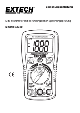
Testboy® TB 312 Version 1.2 Testboy® TB 312 Bedienungsanleitung 3 Testboy® TB 312 Operating Instructions 28 ® Testboy TB 312 Manual de instruções 53 Inhaltsverzeichnis Inhaltsverzeichnis 3 Hinweise 4 Allgemeine Sicherheitshinweise 4 Sicherheitshinweise 6 Bedienung 10 Einleitung 10 Schalter-, Taster- und Buchsenerklärung 12 Display 13 Gleichspannungsmessung / V= 15 Wechselspannungsmessung / V~ 16 Gleichstrommessung / A= 17 Wechselstrommessung / A~ 18 Kapazitätsmessung / F* 19 Widerstandsmessung / Ω 19 Diodentest 20 Durchgangstest 20 Frequenz 21 Tastverhältnis 21 Relativwert Messung 21 Wartung 22 Reinigung 22 Batteriewechsel 22 Sicherungswechsel 22 PC-Software 23 Technische Daten Testboy® TB 312 27 3 DEUTSCH Inhaltsverzeichnis Hinweise Hinweise Allgemeine Sicherheitshinweise WARNUNG Aus Sicherheits- und Zulassungsgründen (CE) ist das eigenmächtige Umbauen und/oder Verändern des Gerätes nicht gestattet. Um einen sicheren Betrieb mit dem Gerät zu gewährleisten, müssen Sie die Sicherheitshinweise, Warnvermerke und das Kapitel "Bestimmungsgemäße Verwendung" unbedingt beachten. WARNUNG Beachten Sie vor dem Gebrauch des Gerätes bitte folgende Hinweise: 4 | Vermeiden Sie einen Betrieb des Gerätes in der Nähe von elektrischen Schweißgeräten, Induktionsheizern und anderen elektromagnetischen Feldern. | Nach abrupten Temperaturwechseln muss das Gerät vor dem Gebrauch zur Stabilisierung ca. 30 Minuten an die neue Umgebungstemperatur angepasst werden um den IR-Sensor zu stabilisieren. | Setzen Sie das Gerät nicht längere Zeit hohen Temperaturen aus. | Vermeiden Sie staubige und feuchte Umgebungsbedingungen. | Messgeräte und Zubehör sind kein Spielzeug und gehören nicht in Kinderhände! | In gewerblichen Einrichtungen sind die Unfallverhütungsvorschriften des Verbandes der gewerblichen Berufsgenossenschaften für elektrische Anlagen und Betriebsmittel zu beachten. Testboy® TB 312 Hinweise Bitte beachten Sie die fünf Sicherheitsregeln: Freischalten Gegen Wiedereinschalten sichern DEUTSCH Spannungsfreiheit feststellen (Spannungsfreiheit ist 2-polig festzustellen) Erden und kurzschließen Benachbarte unter Spannung stehende Teile abdecken Bestimmungsgemäße Verwendung Das Gerät ist nur für die in der Bedienungsanleitung beschriebenen Anwendungen bestimmt. Eine andere Verwendung ist unzulässig und kann zu Unfällen oder Zerstörung des Gerätes führen. Diese Anwendungen führen zu einem sofortigen Erlöschen jeglicher Garantie- und Gewährleistungsansprüche des Bedieners gegenüber dem Hersteller. Um das Gerät vor Beschädigung zu schützen, entfernen Sie bitte bei längerem Nichtgebrauch des Gerätes die Batterien. Bei Sach- oder Personenschäden, die durch unsachgemäße Handhabung oder Nichtbeachtung der Sicherheitshinweise verursacht werden, übernehmen wir keine Haftung. In solchen Fällen erlischt jeder Garantieanspruch. Ein in einem Dreieck befindliches Ausrufezeichen weist auf Sicherheitshinweise in der Bedienungsanleitung hin. Lesen Sie vor Inbetriebnahme die Anleitung komplett durch. Dieses Gerät ist CE-geprüft und erfüllt somit die erforderlichen Richtlinien. Rechte vorbehalten, die Spezifikationen ohne vorherige Ankündigung zu ändern © Testboy GmbH, Deutschland. Testboy® TB 312 5 Hinweise Sicherheitshinweise WARNUNG Gefahrenquellen sind z.B. mechanische Teile, durch die es zu schweren Verletzungen von Personen kommen kann. Auch die Gefährdung von Gegenständen (z.B. die Beschädigung des Gerätes) besteht. WARNUNG Stromschlag kann zum Tod oder zu schweren Verletzungen von Personen führen sowie eine Gefährdung für die Funktion von Gegenständen (z.B. die Beschädigung des Gerätes) sein. 6 Testboy® TB 312 Hinweise Haftungsausschluss DEUTSCH Bei Schäden, die durch Nichtbeachten der Anleitung verursacht werden, erlischt der Garantieanspruch! Für Folgeschäden, die daraus resultieren, übernehmen wir keine Haftung! Testboy haftet nicht für Schäden, die aus | dem Nichtbeachten der Anleitung | von Testboy nicht freigegebenen Änderungen am Produkt oder | von Testboy nicht hergestellten oder nicht freigegebenen Ersatzteilen | Alkohol-, Drogen- oder Medikamenteneinfluss hervorgerufen werden resultieren. Richtigkeit der Bedienungsanleitung Diese Bedienungsanleitung wurde mit großer Sorgfalt erstellt. Für die Richtigkeit und Vollständigkeit der Daten, Abbildungen und Zeichnungen wird keine Gewähr übernommen. Änderungen, Druckfehler und Irrtümer vorbehalten. Entsorgung Sehr geehrter Testboy-Kunde, mit dem Erwerb unseres Produktes haben Sie die Möglichkeit, das Gerät nach Ende seines Lebenszyklus an geeignete Sammelstellen für Elektroschrott zurückzugeben. Die WEEE (2002/96/EC) regelt die Rücknahme und das Recycling von Elektroaltgeräten. Hersteller von Elektrogeräten sind ab dem 13.8.2005 dazu verpflichtet, Elektrogeräte die nach diesem Datum verkauft werden, kostenfrei zurückzunehmen und zu recyceln. Elektrogeräte dürfen dann nicht mehr in die „normalen“ Abfallströme eingebracht werden. Elektrogeräte sind separat zu recyceln und zu entsorgen. Alle Geräte, die unter diese Richtlinie fallen, sind mit diesem Logo gekennzeichnet. Testboy® TB 312 7 Hinweise Entsorgung von gebrauchten Batterien Sie als Endverbraucher sind gesetzlich (Batteriegesetz) zur Rückgabe aller gebrauchten Batterien und Akkus verpflichtet; eine Entsorgung über den Hausmüll ist untersagt! Schadstoffhaltige Batterien/Akkus sind mit nebenstehenden Symbolen gekennzeichnet, die auf das Verbot der Entsorgung über den Hausmüll hinweisen. Die Bezeichnungen für das ausschlaggebende Schwermetall sind: Cd = Cadmium, Hg = Quecksilber, Pb = Blei. Ihre verbrauchten Batterien/Akkus können Sie unentgeltlich bei den Sammelstellen Ihrer Gemeinde oder überall dort abgeben, wo Batterien/Akkus verkauft werden! 5 Jahre Garantie Testboy-Geräte unterliegen einer strengen Qualitätskontrolle. Sollten während der täglichen Praxis dennoch Fehler in der Funktion auftreten, gewähren wir eine Garantie von 5 Jahren (nur gültig mit Rechnung). Fabrikations- oder Materialfehler werden von uns kostenlos beseitigt sofern das Gerät ohne Fremdeinwirkung und ungeöffnet an uns zurückgesandt wird. Beschädigungen durch Sturz oder falsche Handhabung sind vom Garantieanspruch ausgeschlossen. Bitte wenden Sie sich an: Testboy GmbH Elektrotechnische Spezialfabrik Beim Alten Flugplatz 3 D-49377 Vechta Germany [email protected] 8 Tel: 0049 (0)4441 / 89112-10 Fax: 0049 (0)4441 / 84536 www.testboy.de Testboy® TB 312 Hinweise Alle innerhalb der Testboy GmbH durchgeführten, qualitätsrelevanten Tätigkeiten und Prozesse werden permanent durch ein Qualitätsmanagementsystem überwacht. Die Testboy GmbH bestätigt weiterhin, dass die während der Kalibrierung verwendeten Prüfeinrichtungen und Instrumente einer permanenten Prüfmittelüberwachung unterliegen. Konformitätserklärung Das Produkt erfüllt die Niederspannungsrichtlinien 2006/95/EG und die EMV-Richtlinien 2004/108/EG. Testboy® TB 312 9 DEUTSCH Qualitätszertifikat Bedienung Bedienung Einleitung Das Testboy® TB 312 ist ein universell einsetzbares Multimeter. Das Messgerät wird nach den neuesten Sicherheitsvorschriften hergestellt und gewährleistet ein sicheres und zuverlässiges Arbeiten. Das Multimeter ist im handwerklichen oder industriellen Bereich sowie für den Hobby-Elektroniker eine wertvolle Hilfe bei allen StandardMessaufgaben. Lieferumfang | Multimeter TB 312 | Sicherheitsmessleitungen (CAT III 1000 V) | Bedienungsanleitung | PC-Software (CD) | USB Kabel Sicherheitsmaßnahmen Das TB 312 hat das Werk in sicherheitstechnisch einwandfreiem Zustand verlassen. Um diesen Zustand zu erhalten, muss der Anwender die Sicherheitshinweise in dieser Anleitung beachten. Achtung! Benutzen Sie nur die beigefügten Sicherheits-Messleitungen oder äquivalente Messleitungen, die der richtigen Messkategorie CAT III 1000 V genügen. 10 Testboy® TB 312 | Um einen elektrischen Schlag zu vermeiden, sind die Vorsichtsmaßnahmen zu beachten, wenn mit Spannungen größer 70 V (35 V) DC oder 33 V (16 V) eff. AC gearbeitet wird. Diese Werte stellen nach DIN VDE die Grenze der noch berührbaren Spannungen dar. (Werte in Klammern gelten für z.B. medizinische oder landwirtschaftliche Bereiche) | Vor jeder Messung vergewissern, dass die Messleitung und das Prüfgerät in einwandfreiem Zustand sind. | Die Messleitungen und Prüfspitzen dürfen nur an den dafür vorgesehenen Handgriffen angefasst werden. Das Berühren der Prüfspitzen ist unter allen Umständen zu vermeiden. Das Prüfgerät darf nur in den spezifizierten Messbereichen eingesetzt werden. Nach der Norm EN 61010-1 werden folgende Messkategorien definiert: Messkategorie CAT II Messungen an Stromkreisen die elektrisch direkt mit dem Netz verbunden sind, über Stecker in Haushalt, Büro und Labor. Messkategorie CAT III Messungen an der Gebäudeinstallation: Stationäre Verbraucher, Verteileranschluss, Geräte fest am Verteiler. Messkategorie CAT IV Messungen an der Quelle der Niederspannungsinstallation: Zähler, primärer Überspannungsschutz, Hauptanschluss. Testboy® TB 312 11 DEUTSCH Bedienung Bedienung Schalter-, Taster- und Buchsenerklärung 12 (1) V/ Ω/dBm/Hz Buchse Rote Messleitung für alle vom Gerät zulässigen Signalarten. (2) COM Buchse Schwarze Messleitung für alle vom Gerät zulässigen Signalarten. (3) mA Buchse Für Strommessungen bis 500 mA (4) 10 A Buchse (links) Bei Strommessungen ab 500 mA muss die 10 A Buchse benutzt werden. (5) Wahlschalter Messfunktion Bei Betätigung des Drehschalters können die verschiedenen Grundmessarten gewählt werden. (6) POWER Schalter Das Gerät wird über einen „POWER“ Druckschalter ein- und ausgeschaltet. (7) RANGE Taste Manuelle Messbereichswahl (8) SELECT Taste (gelb) Messartwahl (gelbe Beschriftung) (9) WAKE Taste Aufwecken des Gerätes aus dem Schlafmodus (10) MAX/MIN Taste Messwertanzeige MAX, MIN und MAX-MIN Wert (11) REL Taste Umstellung auf Relativwertanzeige (12) HOLD Taste Messwertspeicherung (13) LIGHT Taste Hintergrundbeleuchtung (14) ~ HZ Taste Frequenzmessung während Spannung- und Strommessung (15) LCD Anzeige Siehe unten Testboy® TB 312 Bedienung DEUTSCH Display Nummer Symbol Funktion 1 Temperaturmessung °C oder °F 1 °C °F mnF mμA dBmV 1 MKΩHz 1 1 Kapazitätsmessung nF oder mF Strommessung µA, mA oder A dBm oder Spannungsmessung mV oder V Widerstandsmessung Ω, KΩ oder MΩ Sowie Frequenzmessung Hz, KHz, MHz Tastverhältnis in % 2 3 MAX-MIN Messwerterfassung MAX maximaler, MIN minimaler, MAX-MIN differenzierter Wert 4 AUTO Automatische Messbereichswahl 5 MANUAL Manuelle Messbereichswahl 6 51000 Messwertanzeige 5, 50, 500 und 1000, 5000, usw. 7 8 Testboy® TB 312 Batteriesymbol bei schwacher Batterie Relativmessung 13 Bedienung Durchgangsmessung 9 10 AC Negative Messwert 11 12 DC Please Wait ... Warteanzeige beim Messen von Kapazitäten von 50μF~5000μF im automatischen Messbereich, um die Geneuigkeit zu wahren, bis der Kondensator komplett entladen wurde Analoge Bargraph-Anzeige 15 16 Gleichspannung oder Gleichstrom Messwertspeicherung 13 14 Wechselspannung oder Wechselstrommessung PCLINK USB Anbindung Messwertanzeige 17 14 Testboy® TB 312 Bedienung Mit dem Wahlschalter den geeigneten Bereich (mV oder V) einstellen. Die schwarze Messleitung mit der „COM“-Buchse und die rote Messleitung mit der roten V/mV/Ω Buchse verbinden. Messleitungen mit dem Prüfling verbinden. Messergebnis vom Display ablesen. Die Polarität der Spannung wird ebenfalls angezeigt. Gleichspannung Messbereich Auflösung Genauigkeit 50 mV 0,001 mV ± 0,03 % v.M.+ 10 Digit 500 mV 0,01 mV 5V 0,1 mV 50 V 1 mV 500 V 10 mV 1000 V 0,1 V ± 0,03 % v.M.+ 6 Digit -Eingangswiderstand: 10 MΩ. -Max. Eingangsspannung: 1000 V DC. Durch drücken der SELECT Taste kann zwischen DC, AC und AC+DC Messverfahren umgestellt werden. Testboy® TB 312 15 DEUTSCH Gleichspannungsmessung / V= Bedienung Wechselspannungsmessung / V~ Mit dem Wahlschalter den geeigneten Bereich (mV oder V~) einstellen. Durch Drücken der SELECT Taste auf AC stellen. Die schwarze Messleitung mit der „COM“-Buchse und die rote Messleitung mit der roten V/mV/Ω Buchse verbinden. Messleitungen mit dem Prüfling verbinden. Messergebnis vom Display ablesen. Wechselspannung Messbereich Auflösung 50 mV 0,001 mV 500 mV 0,01 mV 5V 0,1 mV 50 V 1 mV 500 V 10 mV 1000 V 0,1 V Genauigkeit 40 Hz – 1 kHz ± 0,5 % v.M. + 40 Digit 1 kHz – 10 kHz 10 kHz – 20 kHz ± 1 % v.M. + 40 Digit ± 2,5 % v.M. + 40 Digit n. spezifiziert n. spezifiziert n. spezifiziert Angegebene Genauigkeit nur bei 10% bis 100% des Messbereiches gültig. -Eingangswiderstand: 10 MΩ. -Max. Eingangsspannung: 1000 V AC RMS, Frequenzbereich: 40 Hz- 20 kHz. Durch drücken der SELECT Taste kann zwischen dem AC und dBm Messbereich umgestellt werden. 16 Testboy® TB 312 Bedienung Mit dem Wahlschalter den geeigneten Bereich (µA, mA oder A) einstellen. Die schwarze Messleitung mit der „COM“-Buchse und die rote Messleitung mit der mA oder 10A Buchse verbinden. Messleitungen mit dem Prüfling verbinden. Messergebnis vom Display ablesen. Die Stromrichtung wird durch Vorzeichen ebenfalls angezeigt. Bei einem Strom über 500 mA, muss zur Messung die „10 A“Buchse benutzt werden! Gleichstrom Messbereich Auflösung 500 µA 0,01 µA 5000 µA 0,1 µA 5 mA 1 µA 50 mA 10 µA 500 mA 0,1 mA 10 A* 1 mA Genauigkeit ± 0,15 % v.M. + 15 Digit ± 0,5 % v.M. + 10 Digit - 500 mA-Bereich abgesichert durch eine F 500 mA / 1000 V. - 10A-Bereich ist abgesichert durch F 10 A / 1000 V. - im 10A-Bereich maximale Einschaltdauer beachten! * Zum Schutz vor Überhitzung des Gerätes nach max. 10 Sekunden Messung eine Pause von 15 Minuten zwecks Abkühlung einhalten. Durch drücken der SELECT Taste kann zwischen DC, AC und AC+DC Messverfahren umgestellt werden. Testboy® TB 312 17 DEUTSCH Gleichstrommessung / A= Bedienung Wechselstrommessung / A~ Mit dem Wahlschalter den geeigneten Bereich einstellen. Die schwarze Messleitung mit der „COM“-Buchse und die rote Messleitung mit der mA oder 10A Buchse verbinden. Messleitungen mit dem Prüfling verbinden. Messergebnis vom Display ablesen. Bei einem Strom über 500 mA muss zur Messung die „10 A“Buchse benutzt werden! Wechselstrom Messbereich Auflösung 500 µA Genauigkeit 40 Hz – 1 kHz 1 kHz – 10 kHz 10 kHz – 20 kHz 0,01 µA ± 0,75 % v.M. + 20 Digit ± 1 % v.M. + 20 Digit ± 1,2 % v.M. + 5 Digit 5000 µA 0,1 µA ± 0,75 % v.M. + 10 Digit ± 1 % v.M. + 10 Digit ± 1,2 % v.M. + 5 Digit 50 mA 1 µA ± 0,75 % v.M. + 20 Digit ± 1 % v.M. + 20 Digit ± 1,2 % v.M. + 5 Digit 500 mA 10 µA ± 0,75 % v.M. + 10 Digit ± 1 % v.M. + 10 Digit ± 1,2 % v.M. + 5 Digit 5A 0,1 mA ± 0,75 % v.M. + 20 Digit ± 1,5 % v.M. + 20 Digit ± 1,2 % v.M. + 5 Digit 10 A* 1 mA ± 1 % v.M. + 10 Digit ± 1,5 % v.M. + 10 Digit n. spezifiziert Angegebene Genauigkeit nur bei 10% - 100% des Messbereiches gültig. - 500 mA-Bereich ist abgesichert durch F 500 mA / 1000V. - 10A-Bereich ist abgesichert durch F 10 A / 1000 V. - im 10A-Bereich maximale Einschaltdauer beachten! - Frequenzbereich: 40 - 20000 Hz. * Zum Schutz vor Überhitzung des Gerätes nach max. 10 Sekunden Messung eine Pause von 15 Minuten zwecks Abkühlung einhalten. Durch drücken der SELECT Taste kann zwischen DC, AC und AC+DC Messverfahren umgestellt werden. 18 Testboy® TB 312 Bedienung Mit dem Wahlschalter den geeigneten Bereich einstellen. Die schwarze Messleitung mit der „COM“-Buchse und die rote Messleitung mit der V/mV/Ω Buchse verbinden. Messleitungen mit dem Prüfling verbinden. Messergebnis vom Display ablesen. Messbereich Auflösung 50 nF 0,01 nF 500 nF 0,1 nF 5 µF 1 nF 50 µF 10 nF 500 µF 0,1 µF 5000 µF 1 µF Genauigkeit ± 1 % + 5 Digit ± 2 % + 5 Digit Eingangsimpedanz: 180 kΩ, Testspannung: 1,2 V, Teststrom. 2,5 mA *Die Kondensatoren vor jeder Messung entladen! Widerstandsmessung / Ω Mit dem Wahlschalter den geeigneten Bereich einstellen. Die schwarze Messleitung mit der „COM“-Buchse und die rote Messleitung mit der V/mV/Ω Buchse verbinden. Messleitungen mit dem Prüfling verbinden. Messergebnis vom Display ablesen. Messbereich Auflösung Genauigkeit 500 Ω 0,01 Ω ± 0,1 % + 10 Digit 5 kΩ 0,1 Ω 50 kΩ 1Ω 500 kΩ 10 Ω 5 MΩ 100 Ω ± 0,1 % + 10 Digit 50 MΩ 1 kΩ ± 0,5 % + 10 Digit ± 0,1 % + 5 Digit Eingangsimpedanz: 10 MΩ, Testspannung: 3 V, Teststrom: 2 mA. Testboy® TB 312 19 DEUTSCH Kapazitätsmessung / F* Bedienung Diodentest Mit dem Wahlschalter auf „ “ einstellen. Die schwarze Messleitung mit der „COM“Buchse und die rote Messleitung mit der V/mV/Ω Buchse verbinden. Messleitungen mit dem Prüfling verbinden. Rote Messleitung = Anode, Schwarze Messleitung = Kathode. Die Vorwärtsspannungsabfall wird angezeigt. Messbereich Auflösung Anzeige 0,1 mV Vorwärtsspannung -Vorlaufstrom: ca. 0,7 mA, Rücklaufspannung: ca. 2,5 V. Durchgangstest Mit dem Wahlschalter auf „Ω / ◦)))“ einstellen. Mit der SELECT Taste auf Durchgangsprüfung wechseln. Die schwarze Messleitung mit der „COM“-Buchse und die rote Messleitung mit der V/mV/Ω Buchse verbinden. Messleitungen mit dem Prüfkreis verbinden. Bei einem Widerstand unter 60 Ω ertönt ein Signal. Wichtig: Achten Sie auf Spannungsfreiheit und entladene Kondensatoren am Messkreis. Messbereich ◦))) 20 Funktion Der integrierte Summer meldet Durchgang bis 60 Ω Testboy® TB 312 Bedienung Den Wahlschalter auf „Hz“ einstellen. Die schwarze Messleitung mit der „COM“-Buchse und die rote Messleitung mit der V/mV/Ω Buchse verbinden. Messleitungen mit dem Prüfkreis verbinden. Messergebnis vom Display ablesen. Messbereich Auflösung Genauigkeit Logikfrequenz (2,5 ~ 5 Vp) 5 Hz ~ 2 MHz 0,001 Hz ± 0,006 % + 4 Digit Linearfrequenz (500 mV ~ 1000 V, nur im AC Messbereich!) 5 Hz ~ 60 kHz 0,001 Hz ± 0,006 % + 4 Digit - Eingangsimpedanz: 3 kΩ Tastverhältnis Den Wahlschalter auf „Hz“ einstellen. Durch drücken der Taste SELECT auf den Tastverhältnis-Messbereich wechseln. Die schwarze Messleitung mit der „COM“-Buchse und die rote Messleitung mit der V/mV/Ω Buchse verbinden. Messleitungen mit dem Prüfkreis verbinden. Messergebnis vom Display ablesen. Messbereich Auflösung Genauigkeit Tastverhältnis (2,5 ~ 5 Vp bei 5 Hz ~ 60 kHz) 5 % ~ 95 % 0,01 % ± 2 % + 5 Digit - Eingangsimpedanz: 3 kΩ Relativwert Messung Beim Drücken der Taste „REL“ schalten Sie das Relativwert Mssverfahren ein. Beim Drücken der Taste wird der gerade gemessene oder angezeigte Wert festgehalten und dem nachfolgendem abgezogen werden. Die Taste „REL“ kann ebenfalls dazu genutzt werden den Widerstand der messleitungen zu kompensieren. Testboy® TB 312 21 DEUTSCH Frequenz Bedienung Wartung Das Gerät benötigt bei Betrieb gemäß der Bedienungsanleitung keine besondere Wartung. Reinigung Sollte das Gerät durch den täglichen Gebrauch schmutzig geworden sein, kann das Gerät mit einem feuchten Tuch und etwas mildem Haushaltsreiniger gereinigt werden. Niemals scharfe Reiniger oder Lösungsmittel zur Reinigung verwenden. Batteriewechsel Der Batteriewechsel wird nötig, wenn das Batteriesymbol im Display erscheint. Vor dem Batteriewechsel müssen die Messleitungen vom Gerät getrennt sein! Rückseitig befindliche zwei Schrauben unter dem abklappbaren Standfuß entfernen, Batteriefach öffnen und entladene Batterien entfernen. Neue Batterien (6 x 1,5 V AAA Micro) einlegen. Achten Sie auf richtige Polarität. Batteriefach aufsetzen und zuschrauben. Verwenden Sie nur die angegebenen Batterien! Batterien gehören nicht in den Hausmüll! Beachten Sie die gesetzlichen Entsorgungsvorschriften! Sicherungswechsel Bei nötigen Sicherungswechsel vorher Messleitungen vom Gerät entfernen und rückseitige zwei Schrauben des Batteriefaches hinter dem abklappbaren Standfuß lösen. Den batteriefachdeckel vorsichtig entfernen und die entsprechende Schutzkappe der zu wechselnden Sicherung abheben und die defekte Sicherung mit einer des gleichen Typs (Sicherung F 10 A / 1000 V oder F 500 mA / 1000V) ersetzen. Schutzkappe wieder aufsetzen und Batteriefach wieder zuschrauben Verwenden Sie nur Sicherungen mit den angegebenen Werten! 22 Testboy® TB 312 Bedienung PC-Software DEUTSCH Öffnen Sie den Inhalt der CD im Explorer Ihres PC auf und führen Sie die Setup.exe aus. Es erscheint folgendes Auswahlmenü: Klicken Sie auf die entsprechende Schaltfläche für die Sprache. Nun erscheint nach entpacken der Installationsdateien der Installati‐ onsassistent: Testboy® TB 312 23 Bedienung Klicken Sie auf „Next“, wählen Sie den Installationsorder und klicken wieder auf „Next“ und dann auf „Install“, am Ende der Installation auf „Finish“: Unter Programme/Multimeter klicken Sie auf Multimeter.exe oder doppelklicken Sie auf das Multimeter.exe‐Icon auf dem Desktop und es erscheint das Hauptfenster: 24 Testboy® TB 312 Bedienung DEUTSCH Schließen Sie das Multimeter an eine USB‐Schnittstelle Ihres PCs an und halten die Taste „HOLD“ gedrückt, bis „PCLINK“ im Display erscheint. Wenn der Treiber nicht automatisch installiert wird, öffnen Sie auf der CD den Ordner „drivers“ Und führen den xxxInstaller.exe im jeweiligen Ordner Ihres Betriebssystemes aus. Folgende Betriebssysteme werden unterstützt: Windows 2000, XP, 2003, Vista und Windows 7. Nach erfolgter Installation der Treiber wird ine virtuelle COM‐ Schnitstelle generiert, schauen Sie bitte in den Gerätemanager nach dem zugewiesenen COM‐Port (COM2, COM3…). Stellen Sie diesen COM‐Port im Hauptfenster des Programmes links oben ein und drücken auf „Verbindung“. Je nach Stellung des Drehschalters am Multimeter sehen Sie eine Kopie der Anzeige im linken oberen Bereich des Hauptfensters, darunter ein XY‐Diagramm, auf der rechten Seite werden die Date in eine Liste übertragen, die Sie dann einfach speichern, in EXCEL übertragen oder drucken können. Testboy® TB 312 25 Bedienung Mit Hilfe weiterer Werkzeuge könne Sie die Ansicht des XY‐ Diagrammes verändern: Durch Bedienung der oberen Pfeile können Sie die Zeitbasis verändern (X), durch Bedienung der seitlichen Pfeile die Y‐Achse. Durch klicken auf „Druck“ wird der Inhalt der aktuellen Anzeige dem Drucker übergeben. Beenden Sie das Programm indem Sie das Hauptfenster schließen. 26 Testboy® TB 312 Technische Daten Die Genauigkeit bezieht sich auf 1 Jahr bei einer Temperatur von 18 °C - 28 °C mit einer Luftfeuchtigkeit von 75 % (weitere jährliche Kalibrierungen werden angeboten). Max. Spannung zwischen den Anschlussbuchsen und Masse: 1000 V AC / DC. Sicherungen F 500 mA 1000 V flink F10 A 1000 V flink Max. Betriebshöhe 2000 m über NN Displayhöhe 40 mm LCD mit Bargraphanzeige Anzeige max 59999 (4¾ Digit) Polaritätsanzeige automatisch Überlaufanzeige „1“ wird angezeigt Abtastrate ca. 330 ms. Batteriezustand Batteriesymbol wird angezeigt Stromversorgung 6 x 1,5 V AAA Micro Betriebstemperatur 0 °C bis 50 °C RH <80% Lagertemperatur -20 °C bis 60 °C RH <80% Abmessungen 210 x 105 x 45 mm Gewicht 560 g inkl. Batterie Kategorie CAT III 1000 V Schnittstelle USB, optische Ankopplung Testboy® TB 312 27 DEUTSCH Technische Daten Table of Contents Table of Contents Table of Contents 28 Notes 29 General safety notes 29 Safety notes 31 Operation 35 Introduction 35 Switches, buttons and jacks description 37 Display 38 DC voltage measurement / V= 40 AC voltage measurement / V~ 41 DC current measurement / A= 42 AC current measurement / A~ 43 Capacitance measurement / F* 44 Resistance measurement / Ω 44 Diode test 45 Continuity test 45 Frequency 46 Duty cycle 46 Relative value measurement 46 Maintenance 46 Cleaning 47 Changing the batteries 47 Changing the fuse 47 PC software 48 Technical data 28 52 Testboy® TB 312 Notes Notes General safety notes WARNING ENGLISH Unauthorised modification and/or changes to the instrument are not permitted, for reasons of safety and approval (CE). In order to ensure safe and reliable operation using the instrument, you must always observe the safety instructions, warnings and the information contained in the section "Intended use". WARNING Please observe the following information before using the instrument: Testboy® TB 312 | Do not operate the instrument anywhere near electrical welders, induction heaters or other electromagnetic fields. | Further to abrupt temperature fluctuation, the instrument must be allowed to adjust to the new ambient temperature for approx. 30 minutes before using it, in order to stabilise the IR sensor. | Do not expose the instrument to high temperatures for a long period of time. | Avoid dusty and humid environments. | Measuring instruments and their accessories are not toys, and must be kept out of the reach of children! | In industrial facilities, the accident prevention regulations for electrical systems and equipment, established by the employer's liability insurance association, must be observed. 29 Notes Please observe the five safety rules: 1 Disconnect 2 Ensure that the instrument cannot be switched back on again 3 Ensure isolation from the power supply (check that there is no voltage on both poles) 4 Earth and short-circuit 5 Cover adjacent live parts Intended use The instrument is intended strictly for use in applications described in the operating instructions. Any other usage is considered improper and forbidden, and can result in accidents or the destruction of the instrument. Any such application will result in the immediate expiry of all guarantee and warranty claims on the part of the operator against the manufacturer. Remove the batteries if the instrument is not in use for a long period of time, in order to protect the instrument from damage. We assume no liability for damages to property or personal injury caused by improper handling or failure to observe the safety instructions. Any warranty claim expires in such cases. An exclamation mark in a triangle indicates safety notices in the operating instructions. Read the instructions completely before beginning the initial commissioning. This instrument is CE-approved and thus fulfils the required guidelines. All rights reserved to alter specifications without prior notice © Testboy GmbH, Germany. 30 Testboy® TB 312 Notes Safety notes WARNING Sources of danger are mechanical parts, for example, which can cause serious personal injury. Objects are also at risk (e.g. damage to the instrument). An electric shock can result in death or serious personal injury, and also functional damage to objects (e.g. damage to the instrument). Testboy® TB 312 31 ENGLISH WARNING Notes Disclaimer The warranty claim expires in cases of damages caused by failure to observe the instructions! We assume no liability for any resulting damage! Testboy is not responsible for damage resulting from | failure to observe the instructions | changes to the product that have not been approved by Testboy or | the use of replacement parts that have not been approved or manufactured by Testboy | the use of alcohol, drugs or medication. Accuracy of the operating instructions These operating instructions have been compiled with due care and attention. No guarantee is given that the data, illustrations and drawings are complete or correct. All rights reserved with regard to changes, printing mistakes and errors. Disposal Dear Testboy customer: purchasing our product gives you the option of returning the instrument to suitable collection points for waste electrical equipment at the end of its lifespan. The WEEE Directive (2002/96/EC) regulates the return and recycling of waste electrical and electronics equipment. As of 13.08.2005, manufacturers of electrical and electronics equipment are obliged to take back and recycle any electrical devices sold after this date free of charge After that date, electrical devices must no longer be disposed of through the "normal" waste disposal channels. Electrical devices must be recycled and disposed of separately. All devices that fall under this directive must feature this logo. 32 Testboy® TB 312 Notes Disposal of used batteries As an end user, you are legally obliged (battery law) to return all used batteries; disposal with normal domestic waste is prohibited! Batteries containing contaminant material are labelled with adjacent symbols indicating the prohibition of disposal with normal domestic waste. You can return your used batteries free of charge to collection points in your community or anywhere where batteries are sold! 5-year warranty Testboy instruments are subject to strict quality control standards. If, during the course of normal daily use, a fault should occur, we provide a 5-year warranty (valid only with invoice). We will repair production or material defects free of charge upon return, provided the instrument has not been tampered with and is returned to us unopened. Damages resulting from dropping or improper handling are not covered by the warranty. Please contact: Testboy GmbH Electrical Engineering Works Beim Alten Flugplatz 3 D-49377 Vechta Germany [email protected] Testboy® TB 312 Tel: 0049 (0)4441 / 89112-10 Fax: 0049 (0)4441 / 84536 www.testboy.de 33 ENGLISH The abbreviations used for the respective heavy metals are: Cd = cadmium, Hg = mercury, Pb = lead. Notes Certificate of quality All activities and processes carried out within Testboy GmbH relating to quality are monitored permanently within the framework of a Quality Management System. Furthermore, Testboy GmbH confirms that the testing equipment and instruments used during the calibration process are subject to a permanent inspection process. Declaration of conformity This product fulfils the specifications contained in the Low Voltage Directive 2006/95/EC and the EMC Directive 2004/108/EC. 34 Testboy® TB 312 Operation Operation Introduction The Testboy® TB 312 is a universal multimeter. This measuring instrument has been manufactured to the latest safety specifications, and guarantees safe and reliable operation. The multimeter is a valuable aid for all standard measurement tasks in trade and industry as well as for electronics hobbyists. | Multimeter TB 312 | Safety test leads (CAT III 1000 V) | Operating instructions | PC software (CD) | USB cable ENGLISH Scope of delivery Safety precautions The TB 312 left the factory with its safety features in perfect working order. In order to maintain this condition, the user must observe the safety notes contained in this manual. Caution! Use only the enclosed safety test leads or equivalent test leads that meet the correct measurement category CAT III 1000 V. Testboy® TB 312 35 Operation | In order to avoid risk of electric shock, you must observe the specified precautions when working with voltages greater than 70 V (35 V) DC or 33 V (16 V) eff AC. These values represent the limits of safe-to-touch voltages in accordance with DIN VDE. (Values given in brackets apply to medical or agricultural areas, for example) | Before taking each measurement, ensure that the test lead and the test instrument are in perfect working order | The test leads and test probes must only be handled using the grips provided. Avoid touching the test probes under any circumstances. The test instrument must only be used for the measuring ranges specified. According to the standard EN 61010-1, the following measurement categories are defined: Measurement category CAT II Measurements on circuits that are directly electrically connected to the network, via plugs in the home, office and laboratory. Measurement category CAT III Measurements on building installations: fixed consumer units, distributor connection, equipment fitted permanently to the distributor Measurement category CAT IV Measurements at the source of the low voltage installation: meters, primary surge protection, mains connection. 36 Testboy® TB 312 Operation Testboy® TB 312 (1) V/ Ω/dBm/Hz jack Red test lead for all types of signals supported by the instrument. (2) COM jack Black test lead for all types of signals supported by the instrument. (3) mA jack For current measurements up to 500 mA (4) 10 A jack (left) The 10 A jack must be used for current measurements above 500 mA. (5) Measuring function selector switch Use the rotary selector switch to select the various basic measurement modes. (6) POWER switch The device is turned on and off via a "POWER" push-button switch. (7) RANGE button Manual measuring range selection (8) SELECT button (yellow) Measurement type selection (yellow lettering) (9) WAKE button Wakes the instrument from sleep mode (10) MAX/MIN button Measured value display MAX, MIN and MAX-MIN value (11) REL button Switch-over to relative value display (12) HOLD button Measured value storage (13) LIGHT button Backlighting (14) ~ HZ button Frequency measurement during voltage and current measurement (15) LCD display See below 37 ENGLISH Switches, buttons and jacks description Operation Display Number Icon Function 1 Temperature measurement °C or °F 1 °C °F mnF mμA dBmV 1 MKΩHz 1 1 Capacitance measurement nF or mF Current measurement µA, mA or A dBm or voltage measurement mV or V Resistance measurement Ω, KΩ or MΩ Also frequency measurement Hz, KHz, MHz Duty cycle in % 2 3 MAX-MIN Measured value recording MAX maximum, MIN minimum, MAX-MIN differentiated value 4 AUTO Automatic measuring range selection 5 MANUAL Manual measuring range selection 6 51000 Measured value display 5, 50, 500 and 1000, 5000, etc. 7 8 38 Battery icon indicating low battery Relative measurement Testboy® TB 312 Operation Continuity measurement 9 AC Negative measured value 11 12 DC Please Wait … Pause indicator when measuring capacitances of 50μF~5000μF in the automatic measuring range, in order to maintain accuracy until the capacitor has been completely discharged Analogue bargraph display 15 16 Direct voltage or direct current Measured value storage 13 14 Alternating voltage or alternating current measurement PCLINK USB connection Measured value display 17 Testboy® TB 312 39 ENGLISH 10 Operation DC voltage measurement / V= Set the appropriate range (mV or V) using the selector switch. Connect the black test lead to the “COM” jack and the red test lead to the red V/mV/Ω jack. Connect test leads to the test specimen. Read off measurement result from the display. The voltage polarity is also displayed. DC voltage Measuring range Resolution Accuracy 50 mV 0.001 mV ± 0.03 % of meas. val. + 10 digits 500 mV 0.01 mV 5V 0.1 mV 50 V 1 mV 500 V 10 mV 1000 V 0.1 V ± 0.03 % of meas. val.+ 6 digits -Input resistance: 10 MΩ. -Max. input voltage: 1000 V DC. Press the SELECT button to switch between DC, AC and AC+DC measurement methods. 40 Testboy® TB 312 Operation AC voltage measurement / V~ Set the appropriate range (mV or V~) using the selector switch. Press the SELECT button to set to AC. Connect the black test lead to the “COM” jack and the red test lead to the red V/mV/Ω jack. Connect test leads to the test specimen. Read off measurement result from the display. AC voltage Resolution 50 mV 0.001 mV 500 mV 0.01 mV 5V 0.1 mV 50 V 1 mV 500 V 10 mV 1000 V 0.1 V Accuracy 40 Hz – 1 kHz ± 0.5 % of meas. val. + 40 digits 1 kHz – 10 kHz ± 1 % of meas. val. + 40 digits 10 kHz – 20 kHz ± 2.5 % of meas. val. + 40 digits not specified not specified not specified Accuracy specified only valid for 10% to 100% of the measuring range. -Input resistance: 10 MΩ. -Max. input voltage: 1000 V AC RMS, frequency range: 40 Hz- 20 kHz. Press the SELECT button to switch between the AC and dBm measuring range. Testboy® TB 312 41 ENGLISH Measuring range Operation DC current measurement / A= Set the appropriate range (µA, mA or A) using the selector switch. Connect the black test lead to the “COM” jack and the red test lead to the mA or 10A jack. Connect test leads to the test specimen. Read off measurement result from the display. The current direction is indicated by the sign. You must use the “10 A” jack when measuring currents above 500 mA! Direct current Measuring range Resolution 500 µA 0.01 µA 5000 µA 0.1 µA 5 mA 1 µA 50 mA 10 µA 500 mA 0.1 mA 10 A* 1 mA Accuracy ± 0.15 % of meas. val. + 15 digits ± 0.5 % of meas. val. + 10 digits - 500 mA range is protected by a F 500 mA / 1000 V fuse. - 10A range is protected by a F 10 A / 1000 V fuse. - in the 10A range observe the maximum duty cycles! * Following measurement, which should take a max. 10 seconds, allow the instrument to cool down for 15 minutes to protect against overheating. Press the SELECT button to switch between DC, AC and AC+DC measurement methods. 42 Testboy® TB 312 Operation AC current measurement / A~ Set the appropriate range using the selector switch. Connect the black test lead to the “COM” jack and the red test lead to the mA or 10A jack. Connect test leads to the test specimen. Read off measurement result from the display. You must use the “10 A” jack when measuring currents above 500 mA! Alternating current Resolution 500 µA 0.01 µA 5000 µA 0.1 µA 50 mA 1 µA 500 mA 10 µA 5A 0.1 mA 10 A* 1 mA Accuracy 40 Hz – 1 kHz 1 kHz – 10 kHz 10 kHz – 20 kHz ± 0.75 % of meas. val. + 20 digits ± 0.75 % of meas. val. + 10 digits ± 0.75 % of meas. val. + 20 digits ± 0.75 % of meas. val. + 10 digits ± 0.75 % of meas. val. + 20 digits ± 1 % of meas. val. + 10 digits ± 1 % of meas. val. + 20 digits ± 1 % of meas. val. + 10 digits ± 1 % of meas. val. + 20 digits ± 1 % of meas. val. + 10 digits ± 1.5 % of meas. val. + 20 digits ± 1.5 % of meas. val. + 10 digits ± 1.2 % of meas. val. + 5 digits ± 1.2 % of meas. val. + 5 digits ± 1.2 % of meas. val. + 5 digits ± 1.2 % of meas. val. + 5 digits ± 1.2 % of meas. val. + 5 digits not specified Accuracy specified only valid for 10% - 100% of the measuring range. - 500 mA range is protected by a F 500 mA / 1000V fuse. - 10A range is protected by a F 10 A / 1000 V fuse. - in the 10A range observe the maximum duty cycles! - Frequency range: 40 - 20000 Hz. * Following measurement, which should take a max. 10 seconds, allow the instrument to cool down for 15 minutes to protect against overheating. Press the SELECT button to switch between DC, AC and AC+DC measurement methods. Testboy® TB 312 43 ENGLISH Measuring range Operation Capacitance measurement / F* Set the appropriate range using the selector switch. Connect the black test lead to the “COM” jack and the red test lead to the V/mV/Ω jack. Connect test leads to the test specimen. Read off measurement result from the display. Measuring range Resolution 50 nF 0.01 nF 500 nF 0.1 nF 5 µF 1 nF 50 µF 10 nF 500 µF 0.1 µF 5000 µF 1 µF Accuracy ± 1 % + 5 digits ± 2 % + 5 digits Input impedance: 180 kΩ, test voltage: 1,2 V, test current: 2.5 mA *Discharge the capacitors before every measurement! Resistance measurement / Ω Set the appropriate range using the selector switch. Connect the black test lead to the “COM” jack and the red test lead to the V/mV/Ω jack. Connect test leads to the test specimen. Read off measurement result from the display. Measuring range Resolution Accuracy 500 Ω 0.01 Ω ± 0.1 % + 10 digits 5 kΩ 0.1 Ω 50 kΩ 1Ω 500 kΩ 10 Ω 5 MΩ 100 Ω ± 0.1 % + 10 digits 50 MΩ 1 kΩ ± 0.5 % + 10 digits ± 0.1 % + 5 digits Input impedance: 10 MΩ, test voltage: 3 V, test current: 2 mA. 44 Testboy® TB 312 Operation Diode test Set to “ ” using the selector switch. Connect the black test lead to the “COM” jack and the red test lead to the V/mV/Ω jack. Connect test leads to the test specimen. Red test lead = anode, black test lead = cathode. The forward voltage drop is displayed. Measuring range Resolution Display 0.1 mV Forward voltage Continuity test Set to “Ω / ◦)))” using the selector switch. Switch to continuity testing using the SELECT button. Connect the black test lead to the “COM” jack and the red test lead to the V/mV/Ω jack. Connect test leads to the test circuit. A signal is emitted if a resistance under 60 Ω is measured. Important: Ensure isolation from the power supply and discharge capacitors in the circuit to be measured. Measuring range ◦))) Testboy® TB 312 Function The integrated buzzer signals continuity of up to 60 Ω 45 ENGLISH -Forward current: approx. 0.7 mA, flyback voltage: approx. 2.5 V. Operation Frequency Set the selector switch to “Hz”. Connect the black test lead to the “COM” jack and the red test lead to the V/mV/Ω jack. Connect test leads to the test circuit. Read off measurement result from the display. Measuring range Resolution Accuracy Logic frequency (2.5 ~ 5 Vp) 5 Hz ~ 2 MHz 0.001 Hz ± 0.006 % + 4 digits Linear frequency (500 mV ~ 1000 V, only in the AC measuring range!) 5 Hz ~ 60 kHz 0.001 Hz ± 0.006 % + 4 digits - Input impedance: 3 kΩ Duty cycle Set the selector switch to “Hz”. Press the SELECT button to switch to the duty cycle measurement range. Connect the black test lead to the “COM” jack and the red test lead to the V/mV/Ω jack. Connect test leads to the test circuit. Read off measurement result from the display. Measuring range Resolution Accuracy Duty cycle (2.5 ~ 5 Vp at 5 Hz ~ 60 kHz) 5 % ~ 95 % 0.01 % ± 2 % + 5 digits - Input impedance: 3 kΩ Relative value measurement Press the “REL” button to enable the relative value measurement method. Pressing the button retains the last measured or displayed value and deducts the subsequent value. The “REL” button can also be used to compensate for test lead resistance. Maintenance The instrument does not require special maintenance when used as specified in these operating instructions. 46 Testboy® TB 312 Operation Cleaning Use a damp cloth and mild household detergent to clean the instrument should it become soiled through daily use. Never use aggressive cleaning agents or solvents to clean the instrument. Changing the batteries Remove the two screws on the rear of the instrument below the fold-down pedestal, open the battery compartment and remove the spent batteries. Insert new batteries (6 x 1.5 V AAA Micro). Ensure that the polarity is correct. Replace battery compartment and screw tight. Only use the batteries specified! Batteries must not be disposed of with normal domestic waste! Observe the statutory regulations pertaining to disposal! Changing the fuse When you need to change the fuse, first remove the test leads from the instrument and remove the battery compartment's two screws on the rear behind the fold-down pedestal. Carefully remove the battery compartment lid, lift off the relevant protective cap of the fuse that is to be changed and replace the defective fuse with one of the same sort (F 10 A / 1000 V or F 500 mA / 1000V fuse). Replace the protective cap and retighten the screws of the battery compartment. Only use fuses with the values specified! Testboy® TB 312 47 ENGLISH Change the batteries when the battery icon is displayed. Remove the test leads from the instrument before changing the batteries! Operation PC software Open up the contents of the CD in your PC's Explorer and run the Setup.exe. The following drop-down menu appears: Click on the relevant button for the language. After unpacking the installation files, the InstallShield Wizard appears: 48 Testboy® TB 312 Operation ENGLISH Click on “Next”, select the installation directory and click again on “Next” and then on “Install”, and once installation is complete click on “Finish”: Under Programme/Multimeter click on Multimeter.exe or double click on the Multimeter.exe icon on the desktop and the main window appears: Testboy® TB 312 49 Operation Connect the multimeter to a USB port on your PC and hold down the “HOLD” button until “PCLINK” appears on the display. If the driver is not installed automatically, open the “drivers” folder on the CD Run the xxxInstaller.exe in the appropriate folder of your operating system. The following operating systems are supported: Windows 2000, XP, 2003, Vista and Windows 7. Once the drivers have been installed successfully, a virtual COM port is generated. Please refer to the device manager for the assigned COM port (COM2, COM3, etc). Configure this COM port in the program's main window (top left) and press “Connection”. Depending on where the rotary selector switch is positioned on the multimeter, you will see a copy of the display in the top left section of the main window, with an XY plot beneath it, and on the right‐hand side the data is transferred to a list that you can then easily save, transfer to EXCEL or print. 50 Testboy® TB 312 ENGLISH Operation You can change the view of the XY plot using other tools: You can change the time base (X‐axis) by using the top arrows, and the Y‐axis by using the side arrows. Clicking on “Print” sends the contents of the current display to the printer. Exit the programme by closing the main window. Testboy® TB 312 51 Technical data Technical data The accuracy relates to 1 year used at temperatures of 18 °C - 28 °C and 75 % humidity (further annual calibrations are offered). Max. voltage between the connection socket and ground: 1000 V AC / DC. Fuses F 500 mA 1000 V quick-acting F10 A 1000 V quick-acting 52 Max. operating height 2000 m above MSL Height of display 40 mm LCD with bargraph display Display max 59999 (4¾ digits) Polarity indicator Automatic Over-range indicator “1” is displayed Sampling rate Approx. 330 ms. Battery status Battery icon is displayed Power supply 6 x 1.5 V AAA Micro Operating temperature 0 °C to 50 °C RH <80% Storage temperature -20 °C to 60 °C RH <80% Dimensions 210 x 105 x 45 mm Weight 560 g incl. battery Category CAT III 1000 V Interface USB, optical coupling Testboy® TB 312 Índice Índice 53 Avisos 54 Avisos gerais de segurança 54 Avisos de segurança 56 Manuseamento 60 Introdução 60 Explicação de interruptores, botões e tomadas 62 Visor 63 Medição de tensão contínua / V= 65 Medição de tensão alternada / V~ 66 Medição de corrente contínua / A= 67 Medição de corrente alternada / A~ 68 Medição da capacidade / F* 69 Medição da resistência / Ω 69 Teste aos díodos 70 Teste de passagem 70 Frequência 71 Relação de exploração 71 Medição do valor relativo 71 Manutenção 72 Limpeza 72 Substituição das pilhas 72 Mudança de fusíveis 72 Software de PC 73 Dados técnicos Testboy® TB 312 77 53 PORTUGUÊS Índice Avisos Avisos Avisos gerais de segurança ATENÇÃO Por razões de segurança e de homologação (CE) não é permitida a adaptação e/ou alteração construtiva do aparelho. De modo a assegurar o funcionamento seguro do aparelho, é fundamental respeitar os avisos de segurança, as notas de atenção e o capítulo “Utilização adequada”. ATENÇÃO Prestar atenção aos seguintes avisos, antes de utilizar o aparelho: 54 | Evitar o funcionamento do aparelho nas imediações de aparelhos de soldar elétricos, aquecedores de indução e outros campos eletromagnéticos. | Após mudanças abruptas da temperatura e antes da utilização do aparelho, é necessário aguardar aprox. 30 minutos para permitir a sua adaptação à temperatura ambiente, a fim de estabilizar o sensor IR. | Não expor o aparelho durante longos períodos a altas temperaturas. | Evitar condições ambiente húmidas ou com muito pó. | Os aparelhos de medição e acessórios não são brinquedos e devem ser mantidos fora do alcance das crianças! | Nas instalações industriais/profissionais é fundamental respeitar e cumprir as prescrições que visam a prevenção de acidentes da associação profissional competente para equipamentos e ferramentas elétricos. Testboy® TB 312 Avisos Tenha em atenção as cinco regras de segurança: 1 Desconexão 2 Proteger contra uma nova ligação 3 Determinar se há tensão (a presença de tensão deverá ser verificada em 2 polos) 4 Ligar à terra e curto-circuitar 5 Cobrir as peças sob tensão adjacentes Utilização adequada De modo a proteger o aparelho contra danos, deve remover as pilhas/baterias do mesmo, sempre que este não for utilizado durante longos períodos. O fabricante não se responsabiliza por danos pessoais ou materiais resultantes de um manuseamento inadequado ou do desrespeito pelos avisos de segurança. Nestas situações a garantia perde imediatamente a sua validade. Um ponto de exclamação dentro de um triângulo adverte para avisos de segurança no manual de instruções. Ler o completo manual de instruções antes de proceder à colocação em funcionamento. Este aparelho foi verificado e testado de acordo com as disposições da CE e cumpre as diretivas em vigor. Reservamo-nos o direito de alterar as especificações sem aviso prévio ©Testboy GmbH, Deutschland. Testboy® TB 312 55 PORTUGUÊS O aparelho foi concebido única e exclusivamente para as aplicações descritas no manual de instruções. Qualquer outro tipo de utilização é considerado inadequado e pode provocar acidentes ou a destruição do aparelho. Esse tipo de utilização implica a anulação imediata de quaisquer direitos de garantia do utilizador perante o fabricante. Avisos Avisos de segurança ATENÇÃO Fontes de perigo são, por exemplo, peças mecânicas que podem originar ferimentos graves em pessoas. Além disso, também existe o perigo de danos de objetos (p. ex. a danificação do aparelho). ATENÇÃO Um choque elétrico pode causar ferimentos graves em pessoas, bem como falhas de funcionamento de objetos (p. ex. a danificação do aparelho). 56 Testboy® TB 312 Avisos Exoneração de responsabilidade A garantia é anulada no caso de danos resultantes do desrespeito pelo conteúdo das instruções! Não nos responsabilizamos por eventuais danos de consequência! A Testboy não se responsabiliza por danos que sejam resultado | Do desrespeito pelo conteúdo das instruções | De alterações no produto sem o consentimento prévio da Testboy ou | Da utilização de peças sobressalentes não originais ou não autorizadas pela Testboy | Ou consequência do consumo de álcool, drogas ou medicamentos. Exatidão dos dados do manual de instruções Eliminação Exmo. cliente Testboy, com a aquisição do nosso produto tem a possibilidade de o devolver nos pontos de recolha de resíduos eletrónicos, após o fim da vida útil do mesmo. A REEE (2002/96/CE) regula a retoma e a reciclagem de aparelhos elétricos usados. Desde 13.8.2005 os fabricantes de aparelhos elétricos são obrigados a recolher e reciclar gratuitamente todos os produtos que tenham sido vendidos após esta data. Os aparelhos elétricos não podem ser eliminados com os resíduos domésticos “normais”. Os aparelhos elétricos devem ser reciclados e eliminados separadamente. Todos os aparelhos abrangidos por esta diretiva estão assinalados com este logótipo. Testboy® TB 312 57 PORTUGUÊS Este manual de instruções foi elaborado com o máximo cuidado. Não garantimos a exatidão nem a integralidade dos dados, figuras e desenhos. Reservado o direito a alterações, erros de impressão e erros. Avisos Eliminação de pilhas usadas O consumidor final é obrigado de lei (Lei sobre as baterias/pilhas) à devolução de todas as baterias/pilhas usadas; não é permitida a eliminação das mesmas através do lixo doméstico! As baterias/pilhas com substâncias nocivas estão assinaladas com os seguintes símbolos, que advertem para a proibição de eliminação através do lixo doméstico. As designações para os metais pesados importantes são: Cd = cádmio, Hg = mercúrio, Pb = chumbo. As pilhas/baterias usadas podem ser devolvidas gratuitamente em todos os pontos de recolha ou em todos os locais onde são vendidas pilhas/baterias! 5 anos de garantia Os aparelhos Testboy estão sujeitos a exigentes controlos de qualidade. Se durante a utilização diária ocorrerem todavia falhas de funcionamento, oferecemos uma garantia de 5 anos (apenas válida com o recibo/fatura original). Erros de fabrico ou do material são por nós reparados gratuitamente, desde que o aparelho não tenha sido danificado por terceiros e nos seja devolvido em estado fechado. Os danos resultantes de queda ou de um manuseamento inadequado não estão cobertos pela garantia. P. f. entre em contacto com: Testboy GmbH Elektrotechnische Spezialfabrik Beim Alten Flugplatz 3 D-49377 Vechta Germany 58 Tel: 0049 (0)4441 / 89112-10 Fax: 0049 (0)4441 / 84536 www.testboy.de [email protected] Testboy® TB 312 Avisos Certificado de qualidade Todas as atividades e processos relevantes para a qualidade, realizados pela Testboy GmbH, são permanentemente monitorizados por um sistema de gestão da qualidade. A Testboy GmbH confirma ainda que os dispositivos de controlo e instrumentos utilizados durante a calibração estão sujeitos a uma monitorização e controlo permanentes. Declaração CE de Conformidade PORTUGUÊS O produto cumpre as diretivas de baixa tensão 2006/95/CE e as diretivas de compatibilidade eletromagnética 2004/108/CE. Testboy® TB 312 59 Manuseamento Manuseamento Introdução O Testboy® TB 312 é um multímetro de aplicação universal. O aparelho de medição é fabricado obedecendo às mais recentes prescrições de segurança e garante um trabalho seguro e fiável. O multímetro é de grande utilidade para as medições mais comuns em aplicações domésticas ou industriais, bem como para quem aprecia trabalhos de eletrotecnia. São fornecidos | Multímetro TB 312 | Linhas de medição de segurança (CAT III 1000 V) | Manual de instruções | Software de PC (CD) | Cabo USB Medidas de segurança O TB 312 saiu da fábrica em excelentes condições técnicas de segurança. Para o manter assim, o utilizador deve observar as indicações de segurança deste manual. Atenção! Utilize apenas as linhas de medição de segurança fornecidas ou linhas de medição equivalentes, as quais são suficientes para a categoria de medição correta CAT III 1000 V. 60 Testboy® TB 312 Manuseamento | Para evitar choques elétricos, devem ser tomadas precauções caso se trabalhe com tensões superiores a 70 V (35 V) CC ou a 33 V (16 V) CA ef. Segundo as normas DIN VDE, estes valores representam o limite de tensões com as quais ainda se pode ter contacto. (os valores entre parêntesis valem, p. ex., para áreas da medicina ou da agricultura). | Antes de cada medição, garantir que a linha de medição e o aparelho de teste se encontram em bom estado. | As linhas de medição e as pontas de teste só podem ser agarradas pelos punhos previstos para o efeito. Deve evitar-se tocar nas pontas de teste em todas as circunstâncias. O aparelho de teste só pode ser usado nas áreas de medição especificadas. A norma EN 61010-1 define as seguintes categorias de medição: Medições em circuitos elétricos que estão diretamente ligados à rede de forma elétrica, através de ficha no âmbito doméstico, escritório e laboratório. Categoria de medição CAT III Medições na instalação de um edifício: consumidores estacionários, ligação de distribuidor, aparelhos fixos no distribuidor. Categoria de medição CAT IV Medições na fonte da instalação de baixa tensão: contador, proteção contra sobretensões primária, ligação principal. Testboy® TB 312 61 PORTUGUÊS Categoria de medição CAT II Manuseamento Explicação de interruptores, botões e tomadas 62 (1) V/ Ω/dBm/Hz Tomada Linha de medição vermelha para todos os tipos de sinal permitidos do aparelho. (2) COM Tomada Linha de medição preta para todos os tipos de sinal permitidos do aparelho. (3) Tomada mA Para medições de corrente até 500 mA (4) Tomada 10 A (à esquerda) Em medições de corrente a partir de 500 mA tem de ser usada a tomada 10 A. (5) Seletor da função de medição Acionando o interruptor rotativo, podem ser selecionados os vários tipos de medição básicos. (6) Botão POWER O aparelho é ligado e desligado através de um botão “POWER”. (7) Botão RANGE Seleção manual da amplitude de medição (8) Botão SELECT (amarelo) Seleção do tipo de medição (inscrição amarela) (9) Botão WAKE Retirar o aparelho do modo de hibernação (10) Botão MAX/MIN Indicação do valor medido MAX, MIN e MAX-MIN (11) Botão REL Regulação para indicação do valor relativo (12) Botão HOLD Memorização do valor medido (13) Botão LIGHT Iluminação de fundo (14) Botão ~ HZ Medição da frequência durante a medição de tensão e corrente (15) Indicação LCD Ver em baixo Testboy® TB 312 Manuseamento Número Símbolo Função 1 °C °F Medição da temperatura °C ou °F 1 mnF Medição da capacidade nF ou mF 1 mμA Medição de corrente µA, mA ou A 1 dBmV dBm ou medição de tensão mV ou V 1 MKΩHz PORTUGUÊS Visor Medição da resistência Ω, KΩ ou MΩ Bem como medição da frequência Hz, KHz, MHz Relação de exploração em % 2 3 MAX-MIN Registo de valores medidos MAX valor máximo, MIN valor mínimo, MAX-MIN valor diferenciado 4 AUTO Seleção automática da amplitude de medição 5 MANUAL Seleção manual da amplitude de medição 6 51000 Indicação do valor medido 5, 50, 500 e 1000, 5000, etc. 7 Testboy® TB 312 Símbolo de pilha quando a pilha está fraca 63 Manuseamento 8 Medição relativa 9 Medição de passagem 10 AC Valor medido negativo 11 12 DC Tensão contínua ou corrente contínua Memorização do valor medido 13 14 Tensão alternada ou medição de corrente alternada Please Wait ... Indicação para aguardar aquando da medição de capacidades de 50μF~5000μF na amplitude de medição automática, de forma a manter a precisão até o condensador tiver sido totalmente descarregado Indicação analógica do gráfico de barras 15 Ligação USB 16 PCLINK Indicação do valor medido 17 64 Testboy® TB 312 Manuseamento Medição de tensão contínua / V= Com o seletor ajustar a faixa adequada (mV ou V). Ligar a linha de medição preta à tomada “COM” e a linha de medição vermelha à tomada V/mV/Ω vermelha. Ligar as linhas de medição ao dispositivo que se pretende testar. Ler o resultado de medição no visor. A polaridade da tensão é igualmente exibida. Tensão contínua Amplitude de medição Resolução Precisão 50 mV 0,001 mV ± 0,03% v.m. + 10 dígitos 500 mV 0,01 mV 5V 0,1 mV 50 V 1 mV 500 V 10 mV 1000 V 0,1 V ± 0,03% v.m. + 6 dígitos PORTUGUÊS -Resistência de entrada: 10 MΩ. -Resistência de entrada máx.: 1000 V CC. Ao premir o botão SELECT pode alternar entre os procedimentos de medição CC, CA e CA+CC. Testboy® TB 312 65 Manuseamento Medição de tensão alternada / V~ Com o seletor ajustar a faixa adequada (mV ou V~). Ao premir o botão SELECT muda para CA. Ligar a linha de medição preta à tomada "COM" e a linha de medição vermelha à tomada V/mV/Ω vermelha. Ligar as linhas de medição ao dispositivo que se pretende testar. Ler o resultado de medição no visor. Tensão alternada Precisão Amplitude de medição Resolução 50 mV 0,001 mV 500 mV 0,01 mV 5V 0,1 mV 50 V 1 mV 500 V 10 mV 1000 V 0,1 V 40 Hz – 1 kHz ± 0,5% v.m. + 40 dígitos 1 kHz – 10 kHz ± 1% v.m. + 40 dígitos 10 kHz – 20 kHz ± 2,5% v.m. + 40 dígitos n. especificado n. especificado n. especificado Precisão indicada apenas válida com uma amplitude de medição de 10 % a 100 %. -Resistência de entrada: 10 MΩ. -Resistência de entrada máx.: 1000 V CA RMS, gama de frequências: 40 Hz- 20 kHz. Ao premir o botão SELECT pode alternar entre CA e a amplitude de medição dBm. 66 Testboy® TB 312 Manuseamento Medição de corrente contínua / A= Com o seletor ajustar a faixa adequada (µA, mA ou A). Ligar a linha de medição preta à tomada “COM” e a linha de medição vermelha à tomada mA ou 10A. Ligar as linhas de medição ao dispositivo que se pretende testar. Ler o resultado de medição no visor. A direção da corrente é indicada igualmente pelo sinal algébrico. Com uma corrente superior a 500 mA tem de ser usada a tomada “10 A” para a medição! Corrente contínua Resolução 500 µA 0,01 µA 5000 µA 0,1 µA 5 mA 1 µA 50 mA 10 µA 500 mA 0,1 mA 10 A* 1 mA Precisão ± 0,15% v.m. + 15 dígitos PORTUGUÊS Amplitude de medição ± 0,5% v.m. + 10 dígitos - Faixa 500 mA protegida por um F 500 mA / 1000 V. - Faixa 10 A está protegida por F 10 A / 1000 V. - na faixa 10 A ter em atenção o tempo máximo de funcionamento! * Para a proteção contra sobreaquecimento do aparelho após um máx. de 10 segundos de medição, fazer um intervalo de 15 minutos para efeitos de arrefecimento. Ao premir o botão SELECT pode alternar entre os procedimentos de medição CC, CA e CA+CC. Testboy® TB 312 67 Manuseamento Medição de corrente alternada / A~ Com o seletor ajustar a faixa adequada. Ligar a linha de medição preta à tomada “COM” e a linha de medição vermelha à tomada mA ou 10A. Ligar as linhas de medição ao dispositivo que se pretende testar. Ler o resultado de medição no visor. Com uma corrente superior a 500 mA tem de ser usada a tomada “10 A” para a medição! Corrente alternada Amplitude de medição Resolução 500 µA Precisão 40 Hz – 1 kHz 1 kHz – 10 kHz 10 kHz – 20 kHz 0,01 µA ± 0,75% v.m. + 20 dígitos ± 1% v.m. + 20 dígitos ± 1,2% v.m. + 5 dígitos 5000 µA 0,1 µA ± 0,75% v.m. + 10 dígitos ± 1% v.m. + 10 dígitos ± 1,2% v.m. + 5 dígitos 50 mA 1 µA ± 0,75% v.m. + 20 dígitos ± 1% v.m. + 20 dígitos ± 1,2% v.m. + 5 dígitos 500 mA 10 µA ± 0,75% v.m. + 10 dígitos ± 1% v.m. + 10 dígitos ± 1,2% v.m. + 5 dígitos 5A 0,1 mA ± 0,75% v.m. + 20 dígitos ± 1,5% v.m. + 20 dígitos ± 1,2% v.m. + 5 dígitos 10 A* 1 mA ± 1% v.m. + 10 dígitos ± 1,5% v.m. + 10 dígitos n. especificado Precisão indicada apenas válida com uma amplitude de medição de 10 % - 100 %. - Faixa 500 mA está protegida por F 500 mA / 1000 V. - Faixa 10 A está protegida por F 10 A / 1000 V. - na faixa 10 A ter em atenção o tempo máximo de funcionamento! - Gama de frequência: 40 - 20 000 Hz. * Para a proteção contra sobreaquecimento do aparelho após um máx. de 10 segundos de medição, fazer um intervalo de 15 minutos para efeitos de arrefecimento. Ao premir o botão SELECT pode alternar entre os procedimentos de medição CC, CA e CA+CC. 68 Testboy® TB 312 Manuseamento Medição da capacidade / F* Com o seletor ajustar a faixa adequada. Ligar a linha de medição preta à tomada “COM” e a linha de medição vermelha à tomada V/mV/Ω. Ligar as linhas de medição ao dispositivo que se pretende testar. Ler o resultado de medição no visor. Amplitude de medição Resolução 50 nF 0,01 nF 500 nF 0,1 nF 5 µF 1 nF 50 µF 10 nF 500 µF 0,1 µF 5000 µF 1 µF Precisão ± 1% + 5 dígitos ± 2% + 5 dígitos *Descarregar os condensadores antes de cada medição! Medição da resistência / Ω Com o seletor ajustar a faixa adequada. Ligar a linha de medição preta à tomada “COM” e a linha de medição vermelha à tomada V/mV/Ω. Ligar as linhas de medição ao dispositivo que se pretende testar. Ler o resultado de medição no visor. Amplitude de medição Resolução Precisão 500 Ω 0,01 Ω ± 0,1% + 10 dígitos 5 kΩ 0,1 Ω 50 kΩ 1Ω 500 kΩ 10 Ω 5 MΩ 100 Ω ± 0,1% + 5 dígitos ± 0,1% + 10 dígitos 50 MΩ 1 kΩ ± 0,5% + 10 dígitos Impedância de entrada: 10 MΩ, tensão de ensaio: 3 V, corrente de ensaio: 2 mA. Testboy® TB 312 69 PORTUGUÊS Impedância de entrada: 180 kΩ, tensão de ensaio: 1,2 V, corrente de ensaio. 2,5 mA Manuseamento Teste aos díodos Ajustar para “ ” com o seletor. Ligar a linha de medição preta à tomada “COM” e a linha de medição vermelha à tomada V/mV/Ω. Ligar as linhas de medição ao dispositivo que se pretende testar. Linha de medição vermelha = ânodo, linha de medição preta = cátodo. É exibida a queda de tensão direta. Amplitude de medição Resolução Indicação 0,1 mV Tensão direta -Corrente inicial: aprox. 0,7 mA, tensão de retorno: aprox. 2,5 V. Teste de passagem Ajustar para “Ω / ◦)))” com o seletor. Com o botão SELECT mudar para a verificação de passagem. Ligar a linha de medição preta à tomada “COM” e a linha de medição vermelha à tomada V/mV/Ω. Ligar as linhas de medição ao circuito que se pretende testar. Com uma resistência abaixo de 60 Ω, soa um sinal. Importante: verificar se não há tensão e se os condensadores estão descarregados no circuito de medição. Amplitude de medição ◦))) 70 Função O besouro integrado indica uma passagem até 60 Ω Testboy® TB 312 Manuseamento Frequência Ajustar o seletor para “Hz”. Ligar a linha de medição preta à tomada “COM” e a linha de medição vermelha à tomada V/mV/Ω. Ligar as linhas de medição ao circuito que se pretende testar. Ler o resultado de medição no visor. Amplitude de medição Resolução Precisão Frequência lógica (2,5 ~ 5 Vp) 5 Hz ~ 2 MHz 0,001 Hz ± 0,006% + 4 dígitos Frequência linear (500 mV ~ 1000 V, apenas na amplitude de medição CA!) 5 Hz ~ 60 kHz 0,001 Hz ± 0,006% + 4 dígitos - Impedância de entrada: 3 kΩ Relação de exploração Amplitude de medição Resolução PORTUGUÊS Ajustar o seletor para “Hz”. Ao premir o botão SELECT mudar para a amplitude de medição da relação de exploração. Ligar a linha de medição preta à tomada “COM” e a linha de medição vermelha à tomada V/mV/Ω. Ligar as linhas de medição ao circuito que se pretende testar. Ler o resultado de medição no visor. Precisão Relação de exploração (2,5 ~ 5 Vp com 5 Hz ~ 60 kHz) 5% ~ 95% 0,01% ± 2% + 5 dígitos - Impedância de entrada: 3 kΩ Medição do valor relativo Ao premir o botão “REL” irá ligar o procedimento de medição do valor relativo. Ao premir o botão, o valor já medido ou indicado é fixado e deduzido do seguinte. O botão “REL” pode ser usado também para compensar a resistência das linhas de medição. Testboy® TB 312 71 Manuseamento Manutenção Desde que seja usado segundo o manual de instruções, o aparelho não precisa de nenhuma manutenção em especial. Limpeza Se o aparelho se sujar devido ao uso diário, poderá ser limpo com um pano húmido e um pouco de detergente doméstico suave. Nunca usar detergentes abrasivos ou solventes para a limpeza. Substituição das pilhas É necessário mudar as pilhas quando surge o respetivo símbolo no visor. Antes de mudar as pilhas é preciso separar as linhas de medição do aparelho! Remover dois parafusos que se encontram na traseira sob o pé de suporte removível, abrir compartimento das pilhas e retirar as pilhas descarregadas. Colocar pilhas novas (6 × 1,5 V AAA micro). Tenha em atenção a polaridade correta. Fechar o compartimento das pilhas e aparafusar. Usar apenas as pilhas indicadas! As pilhas não devem ser eliminadas juntamente com o lixo doméstico! Respeitar as prescrições legais sobre a eliminação de resíduos! Mudança de fusíveis Se for necessário mudar os fusíveis, remover primeiro as linhas de medição do aparelho e atrás soltar dois parafusos do compartimento das pilhas atrás do pé de suporte removível. Remover cuidadosamente a tampa do compartimento das pilhas e levantar a respetiva tampa de proteção do fusível a substituir, de seguida substituir o fusível avariado por um do mesmo tipo (fusível F 10 A / 1000 V ou F 500 mA / 1000 V). Colocar novamente a tampa de proteção e reaparafusar o compartimento das pilhas Utilize apenas fusíveis com os valores indicados! 72 Testboy® TB 312 Manuseamento Software de PC Abra o conteúdo do CD no explorador do seu PC e execute o Setup.exe. Surge o seguinte menu de seleção: Clique no respetivo campo do idioma. Após a extração dos ficheiros de instalação surge então o assistente de instalação: Testboy® TB 312 73 PORTUGUÊS Manuseamento Clique em “Next”, selecione a pasta de instalação e clique novamente em “Next” e, de seguida, em “Install”; no final da instalação clique em “Finish”: Em Programas/Multímetro clique em Multimeter.exe ou faça duplo clique sobre o ícone Multimeter.exe no ambiente de trabalho, pelo que surgirá a janela principal: 74 Testboy® TB 312 Manuseamento Ligue o multímetro a uma interface USB do seu PC e mantenha o botão “HOLD” premido até surgir “PCLINK” no visor. Se o driver não for automaticamente instalado, abra a pasta “drivers” no CD E execute o xxxInstaller.exe na respetiva pasta do seu sistema operativo. São suportados os seguintes sistemas operativos: Windows 2000, XP, 2003, Vista e Windows 7. Desloque esta porta COM para a janela principal do programa à esquerda em cima e prima “Conexão”. Dependendo da posição do interruptor rotativo no multímetro verá uma cópia da indicação na área superior esquerda da janela principal, em baixo um diagrama XY, no lado direito são transferidos os dados para uma lista que poderá depois facilmente guardar, transferir para um EXCEL ou imprimir. Testboy® TB 312 75 PORTUGUÊS Após a instalação do driver é gerada uma interface COM virtual, procure a porta COM atribuída (COM2, COM3…) no gestor de dispositivos. Manuseamento Com a ajuda de outras ferramentas pode alterar a vista do diagrama XY: Ao operar a seta superior pode alterar a base temporal (X), com a seta lateral o eixo Y. Ao clicar em “Impressão”, o conteúdo da indicação atual é enviado para a impressora. Termine o programa fechando a janela principal. 76 Testboy® TB 312 Dados técnicos Dados técnicos A garantia de precisão vale durante 1 ano e pressupõe a utilização a uma temperatura de 18 °C - 28 °C com uma humidade do ar de 75 % (são disponibilizadas outras calibrações anuais). Tensão máx. entre as tomadas de ligação e a terra: 1000 V CA / CC. Fusíveis F 500 mA 1000 V de ação rápida Altitude máx. de operação 2000 m acima do nível do mar Altura do visor LCD de 40 mm com indicação de gráficos de barras Indicação máx. 59999 (4¾ dígitos) Indicação da polaridade automática Indicação de estouro de capacidade é exibido “1” Frequência de amostragem aprox. 330 ms. Estado das pilhas é exibido o símbolo de pilha Alimentação elétrica 6 × 1,5 V AAA micro Temperatura de serviço 0 °C a 50 °C RH <80 % Temperatura de armazenamento -20 °C a 60 °C RH <80 % Dimensões 210 × 105 × 45 mm Peso 560 g incl. pilha Categoria CAT III 1000 V Interface USB, acoplamento ótico Testboy® TB 312 PORTUGUÊS F10 A 1000 V de ação rápida 77 Testboy GmbH Elektrotechnische Spezialfabrik Beim Alten Flugplatz 3 D-49377 Vechta Germany Tel: 0049 (0)4441 / 89112-10 Fax: 0049 (0)4441 / 84536 www.testboy.de [email protected]
Download