VisualLISA: A Domain Specific Visual Language for
Attribute Grammars
Nuno Oliveira1 , Maria João Varanda Pereira2 , Pedro Rangel Henriques1 , Daniela da
Cruz1 , and Bastian Cramer3
1
University of Minho - Department of Computer Science,
Campus de Gualtar, 4715-057, Braga, Portugal
{nunooliveira,prh,danieladacruz}@di.uminho.pt
2
Polytechnic Institute of Bragança
Campus de Sta. Apolónia, Apartado 134 - 5301-857, Bragança, Portugal
[email protected]
3
University of Paderborn - Department of Informatics
Fürstenallee 11, 33102, Paderborn, Germany
[email protected]
Abstract. The focus of this paper is on the translation of AG formalisms into
a new visual language, and on the development of the associated programming
environment. We present a solution for rapid development of VisualLISA editor using DEViL. This tool uses traditional attribute grammars, to specify the
language’s syntax and semantics, extended by visual representations to be associated with grammar symbols. From these specifications a visual programming
environment is automatically generated. This environment allows us to edit a visual description of an AG that is automatically translated into textual notations.
In this paper, we emphasize the design and implementation of VisualLISA that
is intended to be helpful for beginners and rapid development of small AGs.
1
Introduction
Attribute Grammars (AGs) [1] introduced by Knuth, 40 years ago, is a powerful and
well-known formalism used to create language processors. An AG can be formally defined as the following tuple: AG = (G, A, R, C), where G is a context-free grammar,
A is the set of attributes, R is the set of evaluation rules, and C is the set of contextual
conditions. Each attribute has a type, and represents a specific property of a symbol
X; we write X.a to indicate that attribute a is an element of the set of attributes of X,
denoted by A(X). For each X (terminal or non-terminal), A(X) is divided into two
disjoint sets: the inherited and the synthesized attributes. Each R is a set of formulas,
like X.a = f unc(..., Y.b, ...), that define how to compute, in the precise context of a
production, the value of each attribute. Each C is a set of predicates, pred(..., X.a, ...),
describing the requirements that must be satisfied in the precise context of a production.
As can be deduced from this complex definition of AGs they are not as easy to specify as people would desire because there is a gap between the problem solution (the
desired output) and the source language that must be interpreted. The user must take
care on choosing the appropriate attributes and their evaluation rules. Since the beginning, the literature related with compilers presents AGs using syntax trees decorated
with attributes. So it is usual to sketch up on paper trees with attributes representing
an AG. This strategy allows the developers to imagine a global solution of the problem
(in a higher abstraction level) and to detect complex dependencies between attributes,
symbols and functions, avoiding spending time with syntax details. However, such informal drawings require the designer to translate them manually into the input notation
of a compiler generator. The person who drew it must go through the translation of the
pencil strokes into the concrete syntax of the compiler generator. These inconveniences
make the developers avoid the usage of AGs and go through non systematic ways to
implement the languages and supporting tools. So, in this paper, we develop a Visual
Language (VL), as a meta-language to write AGs, based on a previous conceptualization
that we have proposed in [2].
VLs and consequently the Visual Programming Languages (VPLs) aim at offering
the possibility to solve complex problems by describing their properties or their behavior through graphical/iconic definitions [3]. Icons are used to be composed in a
space with two or more dimensions, defining sentences that are formally accepted by
parsers, where shape, color and relative position of the icons are relevant issues. A
visual programming language implies the existence of a Visual Programming Environment (VPE) [4, 5], because its absence makes the language useless. Commonly, a visual
programming environment consists of an editor, enriched by several tools to analyze, to
process and to transform the drawings.
LISA [6, 7] is a compiler generator based on attribute grammars, developed at University of Maribor at Slovenia. It generates a compiler and several other graphical tools
from a textual AG specification, as can be seen in [8]. Since it generates a set of useful
visual/graphical tools, it would be desirable to have a graphical way of specifying the
AG too.
So the main idea is to enhance the front-end of LISA by developing a VPE, named
VisualLISA, that assures the possibility to specify AGs visually, and to translate them
into LISA specifications or, alternatively, into a universal XML representation designed
to support generic AG specifications. The main objective of this environment is to diminish the difficulties regarding the specification of AGs not only in LISA but also for
other similar systems.
The visual programming environment was automatically generated by DEViL, our
choice among many other tools studied; so in this paper, the system is introduced and its
use explained. However, our objective in this paper is not concerned with the discussion
of compiler development tools, but show the befits of using an effective one.
In Section 2, VisualLISA language and editor are informally described. In Section 3 the language is formally specified, defining syntactic rules, semantic constraints
and translation scheme, which requires the description of the target language — in our
case we present LISA’s syntax (the first target), and X AGra, an XML notation for
AGs that we designed specially to support a universal representation.” In Section 4, the
DEViL generator framework, used for the automatic generation of the visual editor, will
be presented. In Section 5, following the informal conception and its formalization, using DEViL, the visual language and the editor implementation is shown. An overview
on how to use the editor to describe an AG, is given in Section 6 before concluding the
paper in Section 7.
2 VisualLISA - A Domain Specific Visual Language
For many years we have been thinking and working with AGs. Inevitably we created
an abstract mental representation of how it can be regarded and then sketched, for an
easier comprehension and use. So we decided to implement a framework that follows
that representation. The conception of that framework is described in this section.
2.1
The Language Conception
VisualLISA, as a new Domain Specific Visual Language (DSVL) for attribute grammar specification, shall have an attractive and comprehensible layout, besides the easiness of specifying the grammar model.
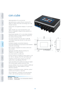
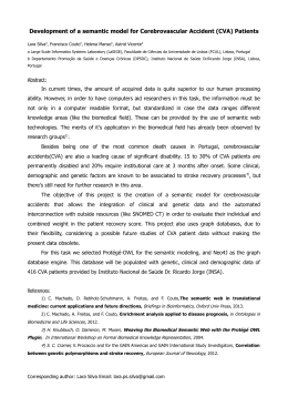
We think that a desirable way to draw an AG is to make it production oriented,
and from there design each production as a tree. The Right-Hand Side (RHS) symbols
should be connected, by means of a visible line, to the Left-Hand Side (LHS) symbol.
The attributes should be connected to the respective symbols, using a connection line
different from the one referred before, as both have different purposes (see Figure 1).
The rules to compute the values of each attribute should exhibit the shape of a function
with its arguments (input attributes) and its results (the output attributes). Two kinds
of functions should be represented: the identity function (when we just want to copy
values) or a generic function (for other kind of computations). Often a production has
a considerable number of attributes and nontrivial computations. Therefore we think
that for visualization purposes, the layout of each production should work as a reusable
template to draw several computation rules. Hence, the rules are drawn separated from
each other, but associated to a production.
Figure 1 depicts a simple example of the conception we made for the language. This
example is based on a simple AG , called Students Grammar, used to process a list of
students, described by their names and ages. The objective of the attribute grammar is
to sum the ages of all the students. This grammar can be textually defined as shown in
Listing 1.1. In Figure 1 just production P1 is shown. The attributes are associated to the
symbols of the production. Moreover, the production has a semantic rule that computes
the value of the LHS’s attribute, sum, by adding the value of the attributes in the RHS
symbols, sum and age.
Listing 1.1. Students Grammar
1
2
3
4
5
6
P1 : S t u d e n t s → S t u d e n t S t u d e n t s
{ S t u d e n t s 0 . sum = S t u d e n t . a g e + S t u d e n t s 1 . sum}
P2 : S t u d e n t s → S t u d e n t
{ S t u d e n t s . sum = S t u d e n t . a g e }
P3 : S t u d e n t → name a g e
{ S t u d e n t . age = age . v a l u e }
Fig. 1. VisualLISA Conception - Production P1.
2.2
The Editor’s Main Features
VisualLISA editor should be compliant with the idea of offering a nice and non errorprone way of sketching the AG, as a first step; and an easy translation of the model into
a target language, as a second step. So, three main features are highlighted: (i) syntax
validation, (ii) semantics verification and (iii) code generation. The syntax validation
restricts some spatial combinations among the icons of the language. In order to avoid
syntactic mistakes, the edition should be syntax-directed. The semantics verification
copes with the static and dynamic semantics of the language. Finally, the code generation feature generates code from the drawings sketched up. The target code would be
LISAsl or X AGra. LISAsl specification generated is intended to be passed to LISA
system in a straightforward step. X AGra specification generated is intended to give the
system more versatility and further usage perspectives.
3
Specification of VisualLISA
The specification of VisualLISA bases on three main issues: i) the definition of the
underlying language’s syntax; ii) the language semantics and iii) the description of the
textual specifications into which the iconic compositions will be translated.
3.1
Syntax
The Picture Layout Grammar (PLG) formalism [9], is an attribute grammar to formally
specify visual languages. It assumes the existence of pre-defined terminal symbols and
a set of spatial relation operators. Our acquaintance with PLG formalism, from previous
works, led us to use it to specify the syntax of VisualLISA. Listings 1.2 present some
parts of the language specification.
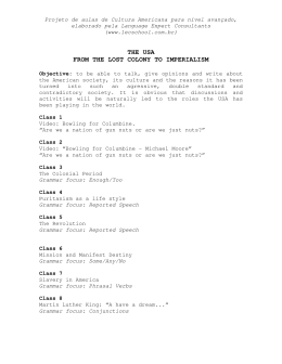
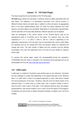
Figure 2 shows the concrete and connector icons used for VisualLISA specifications. LeftSymbol is the LHS of a production, while NonTerminal and Terminal are used
to compose the RHS. The second line of icons in Figure 2 presents the several classes
of attributes. Function and Identity, both representing operations, are used to compute
the attribute values. The other icons connect the concrete symbols with each other, to
rig up the AG.
Listing 1.2. VisualLISA Partial Syntax Definition.
1
2
3
4
5
6
7
8
9
10
11
12
13
14
15
16
17
18
19
20
21
22
23
24
25
AG → c o n t a i n s (VIEW , ROOT)
VIEW → l a b e l s ( t e x t , r e c t a n g l e )
ROOT → l e f t t o ( PRODS , SPECS )
SPECS → c o n t a i n s (VIEW ,
o v e r (LEXEMES, USER FUNCS ) )
PRODS → g r o u p o f (SEMPROD)
SEMPROD → c o n t a i n s (VIEW , l e f t t o (
g r o u p o f ( g r o u p o f ( RULE ELEM ) ) ,
g r o u p o f (AG ELEM) ) )
AG ELEM →
|
|
|
|
|
|
|
|
|
LEFT SYMBOL
NON TERMINAL
TERMINAL
SYNT ATTRIBUTE
INH ATTRIBUTE
TREE BRANCH
INT ATTRIBUTE
SYNT CONNECTION
INH CONNECTION
INT CONNECTION
1
2
3
4
5
6
7
8
9
10
11
12
13
14
15
16
17
18
19
20
21
22
23
24
25
RULE ELEM →
|
|
|
FUNCTION
IDENTITY
FUNCTION ARG
FUNCTION OUT
TERMINAL → l a b e l s ( t e x t , r e c t a n g l e )
INT ATTRIBUTE → l a b e l s ( t e x t , t r i a n g l e )
INT CONNECTION → p o i n t s f r o m (
points to (
dash line ,
∼INT ATTRIBUTE ) ,
∼TERMINAL)
FUNCTION → o v e r ( r e c t a n g l e , t e x t )
FUNCTION OUT → p o i n t s f r o m (
p o i n t s t o ( arrow ,
∼INH ATTRIBUTE ) ,
∼FUNCTION )
| points from (
p o i n t s t o ( arrow ,
∼SYNT ATTRIBUTE ) ,
∼FUNCTION )
LeftSymbol
NonTerminal
Terminal
SyntAttribute
InhAttribute
IntrinsicValueAttribute
Function
SyntConnection
InhConnection
IntrinsicValueConnection
FunctionOut
FunctionArg
Identity
TreeBranch
Fig. 2. The Icons of VisualLISA
3.2
Semantics
In order to correctly specify an AG, many semantic constraints must hold. These constraints are related with the attribute values that depend on the context in which the
associated symbols occur in a sentence. We separated these constraints into two major
groups. One concerning the syntactic rules, Production Constraints (PC), and another
the respective computation rules, Computation Rules Constraints (CRC).
The constraints concerning the VisualLISA’s semantic correctness, are not listed
in this document, for the sake of the space. The complete set of constraints can be seen
in [10].
3.3
Translation
The translation (Ls → τ → Lt ) is the transformation of a source language into a
target language. τ is a mapping between the productions of the Ls (VisualLISA) and
the fragments of Lt (LISAsl ∪ X AGra). These fragments will be specified in this
sub-section.
A Context Free Grammar (CFG) is a formal and robust way of representing LISA
specifications’ structure. Listing 1.3 presents that high-level CFG.
Listing 1.3. LISA structure in a CFG.
1
2
3
4
5
6
7
8
9
10
11
12
p1 : LisaML
p2 : Body
p3 : L e x i c o n
p4 : LexBody
p5 : A t t r i b u t e s
p6 : P r o d u c t i o n s
p7 : D e r i v a t i o n
p8 : Symbs
p9 :
p10 : S e m O p e r a t i o n s
p11 : O p e r a t i o n
p12 : Methods
→ l a n g u a g e i d { Body }
→ L e x i c o n A t t r i b u t e s P r o d u c t i o n s Methods
→ l e x i c o n { LexBody }
→ ( regName r e g E x p ) ?
→ a t t r i b u t e s ( t y p e symbol . a t t N a m e ; ) ?
→ rule id { Derivation } ;
→ symbol : : = Symbs compute { S e m O p e r a t i o n s }
→ symbol +
| epsilon
→ symbol . a t t N a m e = O p e r a t i o n ;
→ ...
→ method i d { j a v a D e c l a r a t i o n s }
Reserved words, written in bold, indicate, in its majority, the beginning of important
fragments. The fact of separating the structure in smaller chunks, makes the process of
generating code easier and modular.
Regarding the literature, there is not an XML standard notation for AGs. So that,
X AGra was defined using a schema. The whole structure of this schema can be separated into five big fragments: i) symbols — where the terminal, nonterminal and the
start symbols are defined; ii) attributesDecl — where information about the attributes
and the symbols to which they are associated is stored; iii) semanticProds — where the
productions and the semantic rules are declared: in each production, the LHS, the RHS
and the attribute computations are defined in a very modular way; iv) importations —
where the modules or packages necessary to perform the computations are declared and
v) functions — is the element where the user declare necessary functions. A more detailed explanation about these elements, their sub-elements and attributes can be seen
in [10].
4 DEViL - A Tool for Automatic Generation of Visual
Programming Environments
We searched for VPE generators like MetaEdit+ [11], but their commercial nature was
not viable for an academic research. Also, we experimented VLDesk [12], Tiger [13],
Atom3 [14] and other similar tools, however none of them gave us the flexibility that
DEViL offered, as described below.
DEViL system generates editors for visual languages from high-level specifications. DEViL (Development Environment for Visual Languages) has been developed at
the University of Paderborn in Germany and is used in many nameable industrial and
educational projects.
The editors generated by DEViL offer syntax-directed editing and all features of
commonly used editors like multi-document environment, copy-and-paste, printing,
save and load of examples. Usability of the generated editors and DEViL and can be
found in [15]. DEViL is based on the compiler generator framework Eli [16], hence
all of Eli’s features can be used as well. Specially the semantic analysis module can be
used to verify a visual language instance and to produce a source-to-source translation.
To specify an editor in DEViL we have to define the semantic model of the visual
language at first. It is defined by the domain specific language DEViL Structure Specification Language (DSSL) which is inspired by object-oriented languages and offers
classes, inheritance, aggregation and the definition of attributes. The next specification
step is to define a concrete graphical representation for the visual language. It is done by
attaching so called visual patterns to the semantic model of the VL specified in DSSL.
Classes and attributes of DSSL inherit from these visual patterns. Visual patterns [17]
describe in what way parts of the syntax tree of the VL are represented graphically, e.g.
we can model that some part should be represented as a “set” or as a “matrix”. DEViL
offers a huge library of precoined patterns like formulae, lists, tables or image primitives. All visual patterns can be adapted through control attributes. E.g. we can define
paddings or colors of all graphical primitives. Technically visual patterns are decorated
to the syntax tree by specifying some easy inheritance rules in a DSL called LIDO.
To analyse the visual language, DEViL offers several ways. The first one results
from the fact that editors generated by DEViL are syntax directed. Hence, the user
cannot construct wrong instances of the VL It is limited by its syntax and cardinalities
expressed in DSSL. Another way is to define check rules e.g. to check the range of
an integer attribute or to do a simple name analysis on a name attribute. To navigate
through the structure tree of the VL, DEViL offers so called path expressions which are
inspired by XPath. They can be used in a small simple DSL to reach every node in the
tree. After analysis, DEViL can generate code from the VL instance. This is done with
the help of Eli which offers unparsers, template mechanism (Pattern-based Text Generator — PTG) and the well-known attribute evaluators from compiler construction.
5
Implementation of VisualLISA
After having all the requirements formally specified (Section 3) and a VPE generator
chosen, the implementation of VisualLISA is a straightforward work and can be
systematized in four main steps: i) Abstract Syntax Specification; ii) Interaction and
Layout Definition; iii) Semantics Implementation; and iv) Code Generation.
5.1
Abstract Syntax
The specification of the abstract syntax of VisualLISA, in DEViL, follows an objectoriented notation, as referred previously. This means that the nonterminal symbols of
the grammar are defined modularly: the symbols can be seen as classes and the attributes
of the symbols as class attributes.
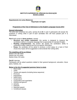
The syntax of the visual language is determined by the relations among their symbols. Therefore, for an high level representation of the language’s syntax, a class diagram can be used. This diagram should meet the structure of the PLG model in Figure 1.2. The final specification for the language is then an easy manual process of converting the diagram into DSSL. Figure 3 shows a small example of the diagram and the
resultant specification.
CLASS Root {
name : VAL V L S t r i n g ;
s e m p r o d s : SUB Semprod ∗;
d e f s : SUB D e f i n i t i o n s ! ;
l i b r a r y : SUB L i b r a r y ? ;
}
1
2
3
4
5
6
Fig. 3. Class Diagram and Respective DEViL Notation
There are two types of classes in this notation: concrete and abstract. The concrete
classes are used to produce a syntax tree, which is manipulated in the other steps of the
environment implementation. The abstract classes are used to group concrete classes
with the purpose of defining syntactic constraints. These classes generate the syntaxdirected editor.
In order to make possible the specification of separated computation rules reusing
the same layout of a production, we used DEViL’s concept of coupled structures [18].
It couples the syntactic structure of two structure tree — for VisualLISA we used
the structure of symbol Semprod, which is used to model a production. In practice, it
means that the layout defined for a production is replicated whenever a computation
rule is defined, maintaining both models synchronized all the time.
5.2
Interaction and Layout
The implementation of this part, in DEViL, consists in the definition of views. A view
can be seen as a window with a dock and an editing area where the language icons are
used to specify the drawing.
VisualLISA Editor is based in four views: rootView, to create a list of productions; prodsView, to model the production layout; rulesView, to specify the semantic
rules reusing the production layout and defsView, to declare global definitions of the
grammar.
At first the buttons of the dock, used to drag structure-objects into the edition area,
are defined. Then the visual shape of the symbols of the grammar for the respective
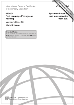
view are defined. Figure 4 shows parts of view definitions and the respective results in
the editor. The code on the left side of Figure 4 defines the view, the buttons and the
behavior of the buttons. The default action is the insertion of a symbol in the editing
area, but it can be extended. The bluish rectangular image represents the button resultant
from that code.
1 VIEW r o o t V i e w ROOT Root{
2
BUTTON IMAGE ” img : : b t n P r o d ”
3
INSERTS Semprod
4
INFO ” P r o d u c t i o n ” ;
5 }
SYMBOL p v i e w N o n T e r m i n a l
INHERITS VPForm
COMPUTE
SYNT . d r a w i n g =
ADDROF( n t D r a w i n g ) ;
END;
1
2
3
4
5
6
Fig. 4. Parts of View Definitions and Respective Visual Outcomes
Symbol NonTerminal is represented by the orange oval in Figure 4. The code on the
right reveals the semantic computation to define the shape of that symbol. Shape and
other visual aspects of the tree-grammar symbols are automatically defined associating,
by inheritance, visual patterns.
5.3
Semantics
As long as VisualLISA is defined by an AG, the contextual conditions could be
checked using the traditional approach. DEViL is very flexible and offers some other
ways to implement this verification module. The approach used to develop VisualLISA,
is completely focused on the contexts of the generated syntax tree. DEViL offers a treewalker, that traverses the tree and for a given context — a symbol of that tree — executes
a verification code, returning an error whenever it occurs. With this approach it is easy
to define data-structures helping the verification process. This approach is very similar
to the generic AG approach, but instead of attributes and semantic rules, it uses variables
which are assigned by the result of queries on the tree of the model.
Listing 1.4 shows the code for the implementation of a constraint defined in [10].
Listing 1.4. Implementation of Constraint: “Every NonTerminal specified in the grammar must be root of one production”
1 c h e c k u t i l : : addCheck Semprod {
2
s e t n [ l l e n g t h [ c : : g e t L i s t {$ o b j . g r a m m a r E l e m e n t s . CHILDREN [ L e f t S y m b o l ] } ] ]
3
s e t symbName [ c : : g e t {$ o b j . name . VALUE}]
4
i f { $n == 0 } {
5
r e t u r n ” P r o d u c t i o n ’ $symbName ’ must h a v e one Root symbol ! ”
6
} e l s e i f {$n > 1} {
7
r e t u r n ” P r o d u c t i o n ’ $symbName ’ must h a v e o n l y one Root symbol ! ”
8
}
9
return ””
10 }
A considerable amount of the constraints defined in Section 3.2 were verified resorting
to the Identifier Table, which is a well known strategy in language processing for that
purpose.
5.4
Code Generation
The last step of the implementation, concerning the translation of the visual AG into
LISA or X AGra, can be done using the AG underlying the visual language (as usual
in language processing). For this task, DEViL supports i) powerful mechanisms to
ease the semantic rules definition; ii) facilities for extend the semantic rules by using
functions and iii) template language (PTG of Eli system) incorporation to structure out
the output code.
The use of patterns (templates) is not mandatory. But, as seen in the formal definition of LISA and X AGra notation (Section 3.3), both of them have static parts which
do not vary from specification to specification. Hence templates are very handy here.
Even with templates, the translation of the visual AG into text is not an easy task. Some
problems arise from the fact that there is not a notion of order in a visual specification.
We used auxiliary functions to sort the RHS symbols by regarding their disposition over
an imaginary X-axe. Based on this approach we also solved issues like the numbering
of repeated symbols in the production definition.
The templates (invoked like functions) and the auxiliary functions, together with
LIDO-specific entities like INCLUDING or CONSTITUENTS, were assembled into semantic rules. These entities collect the values of attributes from different productions at
the same time. Then these values are used by templates or functions in order to define
the translation module. One module was defined for each target notation. New translation modules can be added, for supporting new target notations.
6
AG Specifcation in VisualLISA
Figure 5 shows the editor appearance, presenting the four views of our editor.
Fig. 5. VisualLISA Editor Environment
To specify an attribute grammar the user starts by declaring the productions (in
rootView) and rigging them up by dragging the symbols from the dock to the editing
area (in prodsView), as commonly done in VPEs. The combination of the symbols is
almost automatic, since the editing is syntax-directed. When the production is specified,
and the attributes are already attached to the symbols, the next step is to define the
computation rules. Once again, the user drags the symbols from the dock, in rulesView,
to the editing area, and compounds the computations by linking attributes to each other
using functions. Sometimes it is necessary to resort to user-defined functions that should
be described in defsView. In addition, he can import packages, define new data-types or
define global lexemes.
The AG example addressed in Section 2.1 is composed of three productions with
associated semantic rules. Production P1 is already shown in Figure 1. The other two
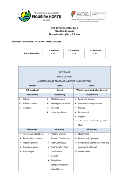
productions are shown in Figure 6.
(a)
(b)
Fig. 6. Specification of Productions P2 and P3, (a) and (b) respectively, with associated semantic
rules.
In production P2, the identity function is used to copy the value of the attribute
age to the attribute sum. Production P3 makes use of terminal symbols and associated
intrinsic values. The computation rule, in this production, is based on the conversion of
the textual value of the age into an integer.
When the grammar is completely specified and semantically correct, code can be
generated. Listing 1.5 shows, in LISA and X AGra notations, the code generated for
production P1 in Figure 1.
Listing 1.5. Code Generated for a) LISA and b) X AGra
1
2
3
4
5
6
a)
rule Student 1 {
STUDENTS : : = STUDENT STUDENTS compute {
STUDENTS . sum = STUDENTS [ 1 ] . sum + STUDENT . a g e ;
};
7 }
8
9
10 b)
11 <s e m a n t i c P r o d name =” S t u d e n t s 1”>
12 <l h s n t =” S t u d e n t s ” />
13 <r h s>
14
<e l e m e n t symbol =” S t u d e n t ” />
15
<e l e m e n t symbol =” S t u d e n t s ” />
16
</r h s>
17 <c o m p u t a t i o n s>
18
<c o m p u t a t i o n name =” sumAges”>
19
<a s s i g n e d A t t r i b u t e a t t =” S t u d e n t s . sum ” p o s i t i o n =”0” />
20
<o p e r a t i o n r e t u r n T y p e =” i n t ”>
21
<a r g u m e n t a t t =” S t u d e n t s . sum ” p o s i t i o n =”2” />
22
<a r g u e m n t a t t =” S t u d e n t . a g e ” p o s i t i o n =”1” />
23
<modus> 1+2 </modus>
24
</ o p e r a t i o n>
25
</c o m p u t a t i o n>
26
</c o m p u t a t i o n s>
27 </s e m a n t i c P r o d>
7
Conclusion
After many years working in specification and implementation of compilers supported
by Attribute Grammars, it became clear that a modular and reusable approach to AG
development is highly recommendable and necessary. On the other hand, the work on
program comprehension tools emphasized the importance of software/data visualization. The combination of those two areas of R&D with a third one, the development of
Visual Languages, gave rise to the proposal of creating a VL for AGs. The obligation
to write text-based AG specifications imposed by several compiler generator tools and
the habitual way of sketching AGs on paper in the form of a decorated tree, shortening
the gap to the mental representation of an AG, reinforced the appropriateness of that
proposal.
In this paper we introduced VisualLISA, a new Domain Specific Visual Language
(DSVL), which enables the specification of AGs in a visual manner and the translation
of that visual AG into LISA or X AGra (an XML notation to support generic AG specifications). We were mainly concerned with the design of the language and its formal
and automatic implementation. In this phase of our project we neither focused on the
usability of the language nor on its scalability. We focused on the specification, aiming at showing the formal work behind the visual outcome, and on the implementation
of the underlying environment to specify AGs. At this point we highlighted the use of
DEViL in order to create the desired environment, through a systematic approach of
development. Also, an example was presented to show the steps to build an AG with
VisualLISA.
In the future, it is our objective to perform at least, two experimental studies involving VisualLISA: one to assess the usability of the language regarding the visual vs textual approaches for developing AGs; and another one to test the scalability
of the language and environment, regarding the hypothesis that it was created to cope
with small AGs. We are also interested in assessing the comprehension of AGs; maybe
VisualLISA would be very handy on this matter, working as AGs visualizer.
References
1. Knuth, D.E.: Semantics of context-free languages. Theory of Computing Systems 2(2) (June
1968) 127–145
2. Pereira, M.J.V., Mernik, M., da Cruz, D., Henriques, P.R.: VisualLISA: a visual interface for
an attribute grammar based compiler-compiler (short paper). In: CoRTA08 — Compilers,
Related Technologies and Applications, Bragança, Portugal. (July 2008)
3. Boshernitsan, M., Downes, M.: Visual programming languages: A survey. Technical report,
University of California, Berkeley, California 94720 (December 2004)
4. Kastens, U., Schmidt, C.: VL-Eli: A generator for visual languages - system demonstration.
Electr. Notes Theor. Comput. Sci. 65(3) (2002)
5. Costagliola, G., Tortora, G., Orefice, S., De Lucia, A.: Automatic generation of visual programming environments. Computer 28(3) (1995) 56–66
6. Mernik, M., Lenič, M., Avdičaušević, E., Žumer, V.: LISA: An interactive environment for
programming language development. Compiler Construction (2002) 1–4
7. Mernik, M., Korbar, N., Žumer, V.: LISA: a tool for automatic language implementation.
SIGPLAN Not. 30(4) (1995) 71–79
8. Henriques, P.R., Pereira, M.J.V., Mernik, M., Lenič, M., Gray, J., Wu, H.: Automatic generation of language-based tools using the lisa system. Software, IEE Proceedings - 152(2)
(2005) 54–69
9. Golin, E.J.: A Method for the Specification and Parsing of Visual Languages. PhD thesis,
Brown University, Department of Computer Science, Providence, RI, USA (May 1991)
10. Oliveira, N., Pereira, M.J.V., da Cruz, D., Henriques, P.R.: VisualLISA. Technical report,
Universidade do Minho (February 2009) www.di.uminho.pt/˜gepl/VisualLISA/
documentation.php.
11. Tolvanen, J.P., Rossi, M.: Metaedit+: defining and using domain-specific modeling languages and code generators. In: OOPSLA ’03: Companion of the 18th annual ACM SIGPLAN conference on Object-oriented programming, systems, languages, and applications,
New York, NY, USA, ACM (2003) 92–93
12. Costagliola, G., Deufemia, V., Polese, G.: A framework for modeling and implementing visual notations with applications to software engineering. ACM Trans. Softw. Eng. Methodol.
13(4) (2004) 431–487
13. Ehrig, K., Ermel, C., Hänsgen, S., Taentzer, G.: Generation of visual editors as eclipse
plug-ins. In: ASE ’05: Proceedings of the 20th IEEE/ACM international Conference on
Automated software engineering, New York, NY, USA, ACM Press (2005) 134–143
14. de Lara, J., Vangheluwe, H.: Atom3: A tool for multi-formalism and meta-modelling. In:
FASE ’02: Proceedings of the 5th International Conference on Fundamental Approaches to
Software Engineering, London, UK, Springer-Verlag (2002) 174–188
15. Schmidt, C., Cramer, B., Kastens, U.: Usability evaluation of a system for implementation
of visual languages. In: Symposium on Visual Languages and Human-Centric Computing,
Coeur d’Alène, Idaho, USA, IEEE Computer Society Press (September 2007) 231–238
16. Gray, R.W., Heuring, V.P., Levi, S.P., Sloane, A.M., Waite, W.M.: Eli: A complete, flexible
compiler construction system. Communications of the ACM 35(2) (February 1992) 121–131
17. Schmidt, C., Kastens, U., Cramer, B.: Using DEViL for implementation of domain-specific
visual languages. In: Proceedings of the 1st Workshop on Domain-Specific Program Development, Nantes, France (July 2006)
18. Schmidt, C.: Generierung von Struktureditoren für anspruchsvolle visuelle Sprachen. Dissertation, Universität Paderborn (January 2006)
Baixar