1
Implementing a hybrid SRAM / eDRAM NUCA
architecture
Javier Lira∗ , Carlos Molina† , David Brooks‡ and Antonio Gonzalez§
of Computer Architecture, Universitat Politècnica de Catalunya, 08034 Barcelona, Spain
† Dept. of Computer Engineering, Universitat Rovira i Virgili, 43007 Tarragona, Spain
‡ School of Engineering and Applied Sciences, Harvard University, 02138 Cambridge, MA (USA)
§ Intel Barcelona Research Center, Intel Labs - UPC, 08034 Barcelona, Spain
[email protected], [email protected], [email protected] and [email protected]
∗ Dept.
Abstract—Advances in technology allowed for integrating
DRAM-like structures into the chip, called embedded DRAM
(eDRAM). This technology has already been successfully
implemented in some GPUs and other graphic-intensive SoC,
R
like game consoles. The most recent processor from IBM,
POWER7, is the first general-purpose processor that integrates
an eDRAM module on the chip. In this paper, we propose a
hybrid cache architecture that exploits the main features of both
memory technologies, speed of SRAM and high density of eDRAM.
We demonstrate, that due to the high locality found in emerging
applications, a high percentage of data that enters to the on-chip
last-level cache are not accessed again before they are evicted.
Based on that observation, we propose a placement scheme where
re-accessed data blocks are stored in fast, but costly in terms of
area and power, SRAM banks, while eDRAM banks store data
blocks that just arrive to the NUCA cache or were demoted from
a SRAM bank. We show that a well-balanced SRAM / eDRAM
NUCA cache can achieve similar performance results than using
a NUCA cache composed of only SRAM banks, but reduces area
by 15% and power consumed by 10%. Furthermore, we also
explore several alternatives to exploit the area reduction we gain by
using the hybrid architecture, resulting in an overall performance
improvement of 4%.
I. I NTRODUCTION
Technology trends are leading to the use of large on-chip
cache memories that typically occupy more than half of the
area of the chip. For example, the most recent architecture
R
from Intel,
Nehalem, introduces up to 24MB shared-L3
cache on the chip, and assigns almost 60% of the chip
area to the cache memory. Cache memories require high
bandwidth and fast response times to minimize the number
of cycles that a core is stalled due to a memory request.
Because of that, traditionally, on-chip cache memories have
been implemented with SRAM cells (6T) which are fast and
simple. Due to their six-transistor implementation, however,
SRAM memories dissipate much more static energy, or
leakage, compared to other kind of memories, like DRAM
whose cells are implemented with only one transistor and
one capacitor. Furthermore, this situation is expected to get
worse as the transistor size shrinks in the future technologies.
Much research has tackled this problem in SRAM cells by
either reducing or removing the power supply to selected
cache blocks [6], [8]. However, although leakage currents are
reduced, they still persist.
Effectively, DRAM memories dissipate much less static
energy than SRAM, however, they are much slower. Actually,
DRAM’s strongest point is their density, which is more than
3x compared to SRAM cells. Because of that, DRAM has
been typically used to implement off-chip memories, where
response time is not so critical. Advances in technology
allowed for integrating DRAM-like structures into the chip,
called embedded DRAM (eDRAM). This technology has
already been successfully implemented in some GPUs
and other graphic-intensive SoC, like game consoles. The
R
most recent processor from IBM,
POWER7, is the first
general-purpose processor that integrates an eDRAM module
on the chip [21]. POWER7 uses eDRAM technology to
implement a shared 32MByte-L3 cache. By using eDRAM
instead of SRAM, POWER7 increases access latency in
its third-level cache by few cycles, however, eDRAM
provides a roughly 3x density improvement as well as about
3.5x lower energy consumption than an equivalent SRAM
implementation. Prior works in the literature also analysed
how to integrate eDRAM technology on the chip efficiently,
but eDRAM was always naively integrated as a last-level cache
[7], [24]. In this paper, we propose a hybrid cache architecture
that exploits the main features of both memory technologies,
speed of SRAM and high density of eDRAM.
The hybrid SRAM / eDRAM cache memory we propose in
this paper is organized on the chip as a Non-Uniform Cache
Architecture (NUCA) design [9]. This kind of cache, which
mitigates the effect of increasing on-chip wire delays in cache
access latency [2], consist of multiple small banks distributed
along the chip that can be accessed independently. Response
time in NUCA caches does not only depend on the latency of
the actual bank, but also the time required to reach the bank
that has the requested data and to send it to the core. So, the
NUCA cache latency relies on the physical distance from the
requesting core to the bank that has the accessed data block.
Furthermore, NUCA caches allow data blocks to be mapped
to several banks, thus a data block can migrate from one bank
to another without leaving the NUCA cache. For instance,
when a data block is accessed by a core, it moves closer to
the requesting core in order to minimize access latency for
future accesses. In this paper we take advantage of migration
movements to share data between SRAM and eDRAM banks.
In this paper we propose a hybrid NUCA cache that
2
SRAM
eDRAM
Access Time (ns)
0.6631
1.4612
Leakage (mW)
93.264
63.908
Area (mm2)
0.4513
0.3162
TABLE I: Physical parameters of SRAM and eDRAM memories. The technology assumed is 45nm2 and their capacity is
64KBytes.
is composed of SRAM banks and eDRAM banks. We
demonstrate, that due to the high locality found in emerging
applications, a high percentage of data that enters to the
on-chip last-level cache are not accessed again before they are
replaced. Based on that observation, we propose a placement
scheme where re-accessed data blocks are stored in fast,
but costly in terms of area and power, SRAM banks, while
eDRAM banks store data blocks that just arrive to the NUCA
cache or were demoted from a SRAM bank. The effectiveness
of this architecture is demonstrated further in this paper. We
show that a well-balanced SRAM / eDRAM NUCA cache
can achieve similar performance results than using a NUCA
cache composed of only SRAM banks, but reducing area by
15% and power consumed by 10%. Furthermore, we also
explore several alternatives to exploit the area reduction we
got by using the hybrid architecture, resulting on an overall
performance improvement of 4%.
Summarizing, the contributions of this paper are as follows:
1) Implement a hybrid NUCA cache that combines both
technologies, SRAM and eDRAM, and make them work
cooperatively at the same cache level on the chip.
2) Analyse the behaviour of the proposed hybrid NUCA
cache and find the configuration that optimize the
trade-off between performance, power and area.
3) Exploit the area and power benefits obtained with the
optimal configuration of the hybrid NUCA cache to
increase the overall performance.
The remainder of this paper is structured as follows. Section
II describes the main characteristics of both technologies,
SRAM and eDRAM. Section III lays out the hybrid NUCA
cache we proposed in this paper. Section IV presents the
experimental method we used, followed by the analysis of
the hybrid SRAM / eDRAM architecture that is presented
in Section V. In Section VI, we show different alternatives
to obtain performance improvements by exploiting area and
power reductions. Related work is discussed in Section VII,
and concluding remarks are given in Section VIII.
II. SRAM VS . E DRAM
SRAM memories are typically used to implement on-chip
cache memories because they are faster and easier to
integrate than other memories, thus they leverage performance.
DRAM memories, however, leverage density. Therefore, this
technology has been traditionally used to implement off-chip
memories. This section describes the main characteristics of
both technologies as well as the role they have in the hybrid
architecture we propose in this paper.
SRAM, which is the core storage element used for
most register files and cache designs on high-performance
microprocessors, is typically implemented with a six-transistor
CMOS cell with cross-coupled inverters as storage elements
and two pass gates as a combination read/write port.
This implementation allows for fast response times and
tightly-coupled integration with processing elements which are
crucial in a high-performance environment, like register files or
low-level caches. On the other hand, as static power dissipated
in a circuit relies on the number of transistors of the actual
implementation, SRAM caches are significantly affected by
leakage currents when they become larger, which is actually
the current trend for last-level caches in recently released
CMPs.
The memory cell used in DRAM arrays consists of one
MOS transistor and a capacitor, where the actual bit is stored.
By using such a small memory cells, DRAMs density is about
3x higher than SRAMs. However, 1T1C DRAM memory cell
should not be considered for high-performance environment,
because a read operation in this memory cell is destructive.
The capacitor on the memory cell gets discharged when it is
read, so data must be refreshed after each read. This refreshing
period stalls the DRAM and cannot be accessed until it is
done, so successive accesses to the same bank must queue
up and serialize. This increases DRAM memories response
time, and thus make them much slower than SRAM. The most
straightforward solution is to simply increase the number of
independent DRAM banks in order to lower the probability
of a conflict. Furthermore, a refresh operation is needed
periodically to restore the charge to the capacitor because the
leakage current of the storage cell reduces the amount of the
stored charge. The refresh operation, which is executed by the
sense amplifiers, is vitally important for the correct operation
of DRAMs.
The hybrid architecture we propose in this paper is
organized as a NUCA cache composed by small banks of
both types, SRAM and eDRAM, which are interconnected
through an on-chip network. The NUCA organization is
further described in Section III. Table I outlines the values
of access time, leakage power and area for both kind of
memories, SRAM and eDRAM1 assuming the same bank size
as in the NUCA cache: 64KBytes. We expected SRAM to
be a bit faster than DRAM caches, but surprisingly, assuming
such a small cache size, SRAM is 2.5x faster than DRAM.
CACTI values also confirm that DRAM cache consumes much
less leakage power than SRAM does. Finally, high-density
eDRAM cache occupies about two-thirds of the area required
by a SRAM cache of the same size.
Based on the features of both technologies, we should build
a hybrid NUCA cache that maximizes the number of hits
in SRAM banks. Moreover, they should be located close to
the cores in order to reduce the overall NUCA latency by
1 SRAM and eDRAM have been modeled with CACTI 5.3. The technology
assumed is 45nm2 and the size of the modeled caches is 64KBytes. More
details of the methodology can be found in Section IV.
3
Core0
Core1
Core2
Core3
Core0
Core1
Core2
Core3
Core4
Core5
Core6
Core7
Core4
Core5
Core6
Core7
eDRAM
SRAM
Bankcluster
(a) Homogeneous bankclusters
eDRAM
SRAM
Bankcluster
(b) Heterogeneous bankclusters
Fig. 1: Scheme of the proposed NUCA organizations.
minimizing routing delays. With regard to the eDRAM, results
on static power and area encourage us to enlarge these banks
as much as possible in the NUCA cache. So, we can get
significant benefits in terms of power and area with the hybrid
architecture.
III. I MPLEMENTING A
HYBRID
SRAM/ E DRAM NUCA
CACHE
A. Baseline architecture
We assume a Non-Uniform Cache Architecture (NUCA) L2
cache, derived from Kim et al.’s Dynamic NUCA (D-NUCA)
design [9]. Similar to the original proposal we partition the
address space across cache banks, which are connected via a
2D mesh interconnection network. As illustrated in Figure 1,
the NUCA storage is partitioned into 128 banks. D-NUCA is
dynamic in the sense that it allows for migration movements
which distribute data blocks among the NUCA banks in order
to have the most accessed data close to the cores, and thus
reduce access latency for future accesses to the same data.
Ideally, a data block could be mapped into any cache bank in
order to maximize placement flexibility, however, the overhead
of locating a data block may be too large as each bank
must be searched, either through a centralized tag store or by
broadcasting the tags to all the banks. To address this situation
all banks in the NUCA cache are treated as a set-associative
structure, and each bank holds one “way” of the set, which
are called banksets. Thus, data blocks can only be mapped to
one bankset. The NUCA banks that compose a bankset are
organized among the NUCA cache in bankclusters (dashed
boxes in Figure 1). Each bankcluster consists of a single
bank of each bankset. As shown in Figure 1, we propose a
NUCA cache 16-way bankset associative that is organized in
16 bankclusters, eight are located close to the cores and the
other eight in the center of the NUCA cache. Therefore, a data
block has 16 possible placements in the NUCA cache (eight
local banks and eight central banks).
The bank where an incoming data block is going to be
mapped when it comes from the off-chip memory is statically
predetermined based on the lower bits of the data block’s
address. The LRU data block in this bank would be evicted if
it is needed. Once the data block is in the NUCA cache, the
migration scheme will determine its optimal position in there.
As migration policy, we assume gradual promotion that has
been widely used in the literature [9], [4]. It defines that upon a
hit in the NUCA cache, the requested data block should move
one-step closer to the core that initiate the memory request.
With regard to the data search scheme, the baseline D-NUCA
design uses partitioned multicast [9], [4]. First, it broadcasts
a request to the local bank that is closest to the processor
that launched the memory request, and to the eight central
banks. If all nine initial requests miss, the request is sent, also
in parallel, to the remaining seven banks from the requested
data’s bankset. Finally, if the request misses all 16 banks, the
request would be forwarded to the off-chip memory.
B. The two hybrid approaches
Figures 1a and 1b show the two different organizations
that we propose for the hybrid NUCA cache. Note that both
architectures define half of the NUCA banks as SRAM banks,
and eDRAM the rest. Based on the main characteristics of
SRAM and eDRAM caches, we first propose an intuitive
approach that organize all SRAM banks close to the cores
and all eDRAM banks in the center of the NUCA cache.
We call it homogeneous bankcluster approach and it is
illustrated in Figure 1a. This approach does not modify any
of the previously described NUCA policies from the baseline
D-NUCA cache. Having all SRAM banks concentrated close
to the cores, we intend to reduce cache access latency for
most accessed data blocks and optimize routing latencies to
the SRAM banks. The main drawback of this approach is that
by having all eDRAM banks in the center of the NUCA cache
it neglects the effect of the migration movements to the shared
data. Note that when a data block is simultaneously accessed
by two or more cores, it is pulled to different locations by the
migration scheme, so it tends to be in the center banks [4].
Figure 1b shows the other organization that we propose. It
combines SRAM and eDRAM banks within a bankcluster, so
we call it heterogeneous bankcluster approach. Compared to
the homogeneous bankcluster approach, this organization is
not biased to optimizing access latency to the most frequently
4
00%
100%
ToeDRAM
90%
80%
Yes
70%
60%
SRAM
50%
40%
@
30%
HIT?
(TDA)
20%
10%
0%
Accessedlines
NonͲAccessedlines
Fig. 2: Percentage of lines that are accessed during their
lifetime in the NUCA cache.
accessed data and fairly distributes the fast SRAM banks
among the NUCA cache. However, this organization requires
SRAM and eDRAM banks to cooperate in order to emphasize
the strengths of both technologies and hide their drawbacks.
C. Placement policy for heterogeneous bankcluster
In general, when a line is requested by a core, it is stored
in the cache memory in order to exploit temporal and spatial
locality found in most applications. Cache memory allows
for reducing memory response time to the following accesses
to the same data and minimizes the number of accesses to
the off-chip memory. However, the higher the cache level,
the less locality it finds. Figure 2 illustrates the percentage
of lines that are accessed during their lifetime in the NUCA
cache. We observe that a significant amount of data (more
than 50%) that are stored in the on-chip last-level cache
memory are not accessed again during their lifetime in the
NUCA cache. It does not mean that they are not accessed
at all, but the lower-level cache satisfied these requests due
to the high-locality found in the application. Based on this
observation, we define a smart placement policy for the
heterogeneous bankcluster NUCA organization that works as
follows: When a data block enters into the NUCA cache from
the off-chip memory, it is located in one of the eDRAM
banks (statically predetermined based on the lower bits of its
address). Then, if it is accessed again the data block moves to
the closest SRAM bank in the bankcluster.
This placement policy assures that SRAM banks store
the hottest most frequently accessed data blocks in the
NUCA cache, while eDRAM banks have data blocks that
were not accessed since they entered to the NUCA cache,
and data blocks that were evicted or demoted from SRAM
banks. Furthermore, the placement policy in the heterogeneous
bankcluster approach introduces the following interesting
features:
1) Accessed data blocks always migrate from a SRAM
bank to another SRAM bank. It means that once a
data block abandons the eDRAM bank to go to a SRAM
bank, it will remain in one of the SRAM banks of the
@A
Fig. 3: Scheme of the Tag Directory Array.
NUCA until other more recently used data block takes
its place.
2) Gradual promotion stays in the SRAM banks but
does not apply for eDRAM banks anymore. There is
no communication between eDRAM banks, if there is
a hit in one those banks, the requested data block will
move towards the closest SRAM bank in the bankcluster.
3) A replacement in a SRAM bank does not provoke
an eviction in the NUCA cache. Data blocks that
come from the off-chip memory are located in eDRAM
banks, so data evictions happen there. SRAM banks, on
the other hand, are fed by promoted data blocks from
eDRAM banks. Consequently, this provokes data blocks
that are evicted from SRAM banks to be demoted to the
eDRAM banks instead of being evicted from the NUCA
cache.
4) There is a tight relationship between a SRAM bank
and an eDRAM bank. Actually, a particular eDRAM
bank could be seen as a kind of extra storage for a
SRAM bank.
D. Tag Directory Array (TDA)
The heterogeneous bankcluster NUCA organization also
allows a data block to be mapped to two banks within
a bankcluster, one SRAM and one eDRAM. Then, the
NUCA cache is 32-way bankset associative in this approach,
which is twice the associativity considered with the
homogeneous bankcluster approach. As described in Section
III-A, increasing the placement flexibility may introduce
significant overheads when locating a data block within the
NUCA cache that could hurt performance and power of the
overall system. Implementing a centralized or distributed tag
structure to boost accesses to the NUCA cache in CMP
appears to be impractical [4]. Apart from requiring huge
hardware overhead, this tag structure could not be quickly
accessed by all processors due to wire delays, and more
importantly, a separate tag structures would require a complex
coherence scheme that updates address location state with
block migrations. To address this situation, we propose using
the baseline access scheme to find the requested data in the
SRAM banks, but also introducing a tag directory array (TDA)
5
20
1.2
2
18
Powerconsumption(W)
Perform
mancespp
pedͲup
1.15
1.1
1.05
1
0.95
16
14
12
10
8
6
4
2
0.9
0
0 85
0.85
ABC
A:Hom.B:Het.andC:Het.+TDA
Hom.
Het.
Het.+TDAs
(a) Performance
Dyn.Network
Dyn.Cache
Sta.Network
Sta.SRAM
Sta.eDRAM
Sta.TDA
(b) Power consumption
Fig. 4: Results of the three approches described in this section.
per eDRAM bank in order to avoid accessing to any of these
banks if they do not have the requested data. As there is
no migration between eDRAM banks and each TDA only
manages the closest eDRAM bank, this structure does not
incur on the overheads previously described for tag structures
that manage the whole NUCA cache.
A particular TDA contains the tags of all data blocks that
a particular eDRAM bank is storing. In order to provide
high-perfomance access, the TDA is implemented using
SRAM technology. As illustrated in Figure 3, each TDA is
physically located jointly with a SRAM bank. Thus, when a
request arrives to the SRAM bank, the joint TDA receives
it as well. Then, both structures, the SRAM bank and the
TDA, are accessed in parallel, so we prioritise performance at
the cost of increasing dynamic power. Finally, if the request
hits on the TDA, it is forwarded to the related eDRAM bank,
otherwise the request is discarded. By using TDAs, although a
data block could be in any of the 32 possible locations within
NUCA cache, the implemented lookup algorithm will only
need to access up to 17 banks (16 SRAM banks and one
eDRAM). This mechanism, however, presents some overheads
that should be considered. The most obvious one is the
extra hardware required to implement TDAs. For example,
assuming an hybrid 4-MByte-SRAM + 4-MByte-eDRAM
heterogeneous bankcluster NUCA organization, the total
hardware required to implement all TDAs would be 512
KBytes, with each TDA requiring 8 KBytes. The required area
and the power dissipated by this structure will be considered
when we analyse this mechanism further in this paper. In
order to keep each TDA updated, all allocate and deallocate
operations in the related eDRAM are synchonized by this
structure. Therefore, we maintain correctness in TDAs data
at the cost of making these operations a bit slower.
and power consumption, respectively2. Performance results
emphasize the necessity of using TDAs with the heterogeneous
bankcluster approach. While both approaches, homogeneous
and heterogeneous without TDAs, achieve similar performance
results, the introduction of TDAs improve performance of the
latter by almost 7%. Furthermore, Figure 4b illustrates that
the power consumed by the heterogeneous bankcluster NUCA
organization does not increase when using TDAs, it actually
decreases. Because of the bankset-associativity increase, when
TDAs are not considered, the heterogeneous bankcluster
approach must access more banks to find the requested data
block, and thus, it consumes much more dynamic power
than the other considered approaches. Although homogeneous
bankcluster is the architecture that consumes less power, it
does not perform so well. Having all eDRAM banks in the
center of the NUCA, this approach is heavily penalized by
shared data blocks because they concentrate to these slow
banks. In general, we consider the heterogeneous bankcluster
approach with TDAs the best choice to be our hybrid NUCA
architecture. It performs significantly well assuming both
simulated environments, multi-programmed and emerging
parallel applications, and it is not constrained by power
consumption. Therefore, in the remainder of this paper, we
will not evaluate other approaches and will assume we are
using the heterogeneous bankcluster approach with TDAs as
hybrid NUCA architecture.
E. Performance and power analysis
IV. E XPERIMENTAL METHODOLOGY
In order to evaluate the proposed architectures, we used the
full-system execution-driven simulator, Simics [11], extended
with the GEMS toolset [12]. GEMS provides a detailed
memory-system timing model that enabled us to model the
presented approaches. Besides, it also integrates a power
model based on Orion [20] that we used to evaluate the
static and dynamic power consumed by the on-chip network.
We have modeled cache memories considered in this paper
with CACTI 5.3 [18], which includes support for eDRAM
Figures 4a and 4b show how the hybrid approaches that
we described in this section behave in terms of performance
2 For each approach, we assumed an hybrid 4-MByte-SRAM +
4-MByte-eDRAM NUCA organization. More details of the experimental
methodology used are described in Section IV.
6
caches. It outlines the optimal physical characteristics (e.g.
area, access latency and leakage) of the modeled memories.
In order to validate CACTI results, we have modeled a real
eDRAM macro [16] and found that they are very similar
to the actual physical parameters. Thus, we used physical
parameters provided by CACTI to evaluate static power
consumed and the area required by the memory structures.
CACTI has been used to evaluate dynamic power consumption
as well, but GEMS support is required in this case to ascertain
the dynamic behaviour in the applications. The simulated
architecture is structured as a single CMP made up of eight
UltraSPARC IIIi homogeneous cores. With regard to the
memory hierarchy, each core provides a split first-level cache
(data and instructions). The second level of the memory
hierarchy is the NUCA cache. In order to maintain coherency
along the memory subsystem, we used the MESIF coherence
R Nehalem processor
protocol, which is also used in the Intel
[13]. The access latencies of the memory structures are based
on CACTI models. Table II outlines the most important
configuration parameters used in our studies.
Processors
Frequency
Integration Technology
Block size
L1 Cache (Instr./Data)
L2 Cache (NUCA)
L1 Latency
Router Latency
Avg Offchip Latency
8 - UltraSPARC IIIi
3 GHz
45 nm
64 bytes
32 KBytes, 2-way
8 MBytes, 128 Banks
3 cycles
1 cycle
250 cycles
TABLE II: Configuration parameters.
We assume two different scenarios: 1) Multi-programmed
and 2) Parallel applications. The former executes in parallel
a set of eight different SPEC CPU2006 [1] workloads with
the reference input. Table III outlines the workloads that
make up this scenario. The latter simulates the whole set of
applications from the PARSEC v2.0 benchmark suite [5] with
the simlarge input data sets. This suite contains 13 programs
from many different areas such as image processing, financial
analytics, video encoding, computer vision and animation
physics, among others.
astar
milc
gcc
lbm
omnetpp
perlbench
Reference input
mcf
soplex
TABLE III: Multi-programmed scenario.
The method we used for the simulations involved first
skipping both the initialization and thread creation phases, and
then fast-forwarding while warming all caches for 500 million
cycles. Finally, we performed a detailed simulation for 500
million cycles. As performance metric, we use the aggregate
number of user instructions committed per cycle, which is
proportional to the overall system throughput [22].
V. E VALUATION
OF THE HYBRID
NUCA
CACHE
This section analyses how the hybrid SRAM / eDRAM
NUCA architecture presented in Section III behaves in
terms of performance, power and area compared to other
homogeneous schemes, such as the traditional SRAM NUCA
cache, or the same but composed of only eDRAM banks.
For the sake of simplicity, all evaluated configurations assume
the same NUCA architecture (Figure 1b), so the following
parameters do not change along the different configurations:
the number of banks in the NUCA cache, on-chip network
organization and global NUCA cache size. The configurations
evaluated in this section are as follows: 1) all-SRAM NUCA
cache, 2) range of hybrid approaches, and 3) all-eDRAM
NUCA cache. The former and the latter assume an 8-MByte
NUCA cache composed of 128 banks, and behave as described
in Section III-A. The hybrid approach also assumes an
8-MByte NUCA cache, but composed of 64 SRAM banks
and 64 eDRAM banks. Moreover, in this case we consider
seven different configurations by changing the size of the
NUCA dedicated to SRAM and eDRAM. This will allow
us to find the configuration that better leverages the trade-off
between performance, power and area. Table IV outlines the
most relevant parameters of the NUCA banks used in the
different configurations. In the remainder of the paper we
will refer to a X-MByte-SRAM + Y-MByte-eDRAM hybrid
NUCA architecture as XS-YD.
A. Performance Analysis
Figure 5a shows how the hybrid NUCA architecture behaves
in terms of performance compared to an all-SRAM-bank
NUCA cache. We find that, on average, our hybrid approach
can get similar performance results compared to the all-SRAM
configuration when considering the proper configuration.
Actually, several hybrid configurations, like 5S-3D or 4S-4D,
achieve almost 97% of the performance achieved by
all-SRAM. Assuming an all-eDRAM NUCA cache, however,
performance is reduced by 13%. Figure 5b illustrates the
main reason that make our hybrid approach performs so well
compared to both homogeneous configurations, all-SRAM and
all-eDRAM: the placement policy proposed for the hybrid
architecture succeeds in concentrating most of hits in NUCA
in the fast SRAM banks, so even dedicating little size to the
SRAM banks, most of hits in the NUCA cache happen in the
SRAM banks.
By taking into consideration the features of both
technologies, SRAM and eDRAM, one could expect that the
more size the hybrid NUCA dedicates to SRAM, the better it
performs. However, Figure 5a shows that the best performing
configurations are those that dedicate about the same size
to SRAM and eDRAM banks. As described in Section III,
when a data block enters into the NUCA cache it is located
into an eDRAM bank. If it is later accessed, then it moves
forward to a SRAM bank. This placement decision makes
configurations with small eDRAM banks barely effective in
terms of performance because, in most cases, data blocks
are evicted from the NUCA cache before being accessed for
second time, and thus could not move to the SRAM part.
Surprisingly, Figure 5a shows that some hybrid
configurations outperform all-SRAM (e.g. bodytrack,
streamcluster and vips). This is because our hybrid
7
Dynamic
Leakage
Area
Latency
Dynamic
Leakage
Area
Size
Latency
Dynamic
Leakage
Area
MByte
MBytes
MBytes
MBytes∗
MBytes
MBytes
MBytes
TDA
Latency
1
2
3
4
5
6
7
eDRAM
Size
SRAM
KB
16
32
48
64
80
96
112
ns
0.59
0.61
0.63
0.66
0.68
0.69
0.71
mW
40.30
45.35
47.91
49.34
52.75
55.30
58.34
mW
30.80
51.44
72.03
93.26
114.04
135.51
156.40
mm2
0.12
0.23
0.34
0.45
0.56
0.67
0.78
ns
1.26
1.31
1.43
1.46
1.54
1.60
1.69
mW
40.54
44.13
46.93
49.51
53.78
56.58
59.73
mW
20.24
35.03
49.35
63.91
76.83
91.62
105.13
mm2
0.09
0.17
0.25
0.32
0.41
0.47
0.55
KB
2
4
6
8
10
12
14
ns
0.39
0.42
0.45
0.49
0.53
0.56
0.57
mW
22.64
23.83
25.64
28.83
33.51
34.03
34.55
mW
1.48
2.50
3.28
4.35
5.39
6.60
7.61
mm2
0.013
0.021
0.028
0.036
0.042
0.053
0.068
TABLE IV: Parameters for each configuration got from CACTI models. For example, the shaded parameters are used by the
hybrid configuration 2S-6D. ∗ All banks in both homogeneous configurations are like the 4-MByte configuration.
1.05
100%
90%
Perform
mancespeedͲup
1
80%
0.95
70%
60%
0.9
50%
0.85
40%
30%
0.8
20%
0.75
10%
0%
allͲSRAM
AllͲSRAM
7SͲ1D
6SͲ2D
5SͲ3D
4SͲ4D
3SͲ5D
2SͲ6D
1SͲ7D
AllͲeDRAM
(a) Performance
7SͲ1D
6SͲ2D
5SͲ3D
SRAM
4SͲ4D
3SͲ5D
2SͲ6D
1SͲ7D
allͲeDRAM
eDRAM
(b) Hit distribution.
Fig. 5: Evaluation of different configurations using the NUCA architecture described in Section III.
architecture increases the bank-set associativity assumed
with the homogeneous configurations, then there are more
data elegible to be mapped to the SRAM banks. In order
to describe better this situation, we will use the following
example. A data block that is located in the second row
of banks would be in its optimal location for a core in
the all-SRAM configuration, however, assuming our hybrid
architecture, this data would be in an eDRAM bank, so it
could move forward to an SRAM bank in the first row, thus
having faster access latency for future accesses.
B. Power and Area Analysis
Figure 6a shows the power consumed by each configuration
assumed in this analysis. We normalized the power
consumption results to the all-SRAM configuration, which
is the configuration that dissipates more leakage power, and
consequently, consumes more power in general. The major
contributor (close to 70%) of power consumption results
is static power. On the other hand, due to the use of
the power-efficient eDRAM technology, the all-eDRAM is
the least power-consuming configuration, reducing the power
consumed by the all-SRAM configuration by 22%. With regard
to the hybrid configurations, the less SRAM they use, the less
power they consume. In general, their power consumption
results range from 3% (7S-1D) to 18% (1S-7D) reduction
compared to the all-SRAM configuration. Figure 6a also
shows that the overhead associated to TDAs in terms of
power consumption is only 2% assuming the most pessimistic
hybrid configuration: 1S-7D. Using TDAs, however, the hybrid
architectures prevent accessing all eDRAM banks for each
request to the NUCA cache, and thus it prevents increasing
dynamic power requirements in these configurations.
With regard to the requirements in terms of die area, Figure
6b illustrates the area reduction obtained with the hybrid
architecture compared to the all-SRAM configuration. Similar
to the trend observed on the power consumption results, the
less SRAM the configurations use, the less area they require.
The all-eDRAM configuration would occupy less than 70%
of area compared to the all-SRAM. The area reduction of the
hybrid architecture ranges from 2% (7S-1D) to 21% (1S-7D).
In this case, the area overhead introduced by TDAs is not
insignificant (up to 10%), however, as previously shown in this
section, this structure is necessary to get performance results
similar to the all-SRAM configuration and to reduce dynamic
power consumption.
C. Choosing the best hybrid configuration
This section shows that the hybrid architecture described in
Section III succeeds in combining both technologies, SRAM
and eDRAM, in a NUCA cache. We observed that the
placement policy assumed benefits these configurations that
dedicate about the same size to SRAM and eDRAM banks,
8
1.2
2
1
1
0.8
08
0.8
0.6
Arrea
Powerco
onsumptio
on(norm.)
1.2
0.4
0.4
02
0.2
0
06
0.6
0.2
ABCDEFGHI
0
A:AllSRAM,B:7SͲ1D,C:6SͲ2D,D:5SͲ3D,E:4SͲ4D,F:3SͲ5D,G:2SͲ6D,H:1SͲ7DandI:AlleDRAM
Dyn.Network
Dyn.Cache
Sta.Network
Sta.SRAM
Sta.eDRAM
Sta.TDAs
AllSRAM
7SͲ1D
6SͲ2D
5SͲ3D
SRAM
4SͲ4D
eDRAM
3SͲ5D
2SͲ6D
1SͲ7D
AlleDRAM
TDA
(b) Area
(a) Power consumption
Fig. 6: Power and area results of the configurations assumed.
1.05
1
All SRAM
AllSRAM
0.95
0 95
Pow
wer
7SͲ 1D
6SͲ 2D
09
0.9
5SͲ 3D
4SͲ 4D
3SͲ 5D
0.85
0 85
2SͲ 6D
1SͲ 7D
0.8
All eDRAM
AlleDRAM
0.75
0.85
0.9
0.95
1
1.05
PerformancexArea
Fig. 7: Trade-off between Power x Performance x Area.
and other imbalanced configurations are not so effective. In
order to decide the best hybrid configuration, we could use
popular metrics like ED or ED2 to analyse the performance
and power trade-off. However, these metrics does not consider
the area required by the configuration, which is very important
in our design. So, we have used a recently proposed
metric Power x (Performance x Area) [3] that takes into
account the three terms of the trade-off to analyse. Assuming
the scheme shown in Figure 7, we choose 4S-4D as the
best hybrid configuration. This configuration is neither the
best-performing one nor the one that dissipates less power,
however, it is the one that leverages better the trade-off
between performance, power and area. This is our choice,
but in this section we evaluated a wide range of hybrid
configurations and showed the main characteristics of all
of them. Based on this analysis, architects can choose the
hybrid configuration that better fits to their needs, e.g. high
performance, low power consumption, or small area.
VI. E XPLOITING
ARCHITECTURALS BENEFITS
Section V shows that a well-balanced configuration of
the proposed hybrid NUCA architecture achieves similar
performance results to an architecture composed of only
SRAM banks, but occupies about 15% less area and dissipates
10% less power. Architects could manage this significant
area reduction to either implement smaller and more
power-efficient designs, or re-design architectural structures
to improve overall performance. For example, the most recent
R Nehalem, assigns more than 50%
architecture from Intel,
of the chip area to the last-level cache memory, thus the area
reduced of using the proposed hybrid architecture as last-level
cache in this processor would be enough to integrate an extra
core.
In this section, we evaluate two different scenarios assuming
that the remaining transistors are used to increase the
last-level cache memory size. Thus, assuming the best hybrid
configuration, we increase either the size designated to SRAM
banks, or to eDRAM banks. The 15% area reduction allows for
integrating up to 1 MByte extra to the SRAM banks, resulting
a 5-MByte-SRAM + 4-MByte-eDRAM hybrid configuration.
On the other hand, assuming eDRAM’s higher density,
architects could manage to re-design the 4S-4D configuration
by dedicating up to 6 MBytes to the eDRAM banks. Both
configurations, 5S-4D and 4S-6D, occupy almost the same
area as a NUCA architecture composed of only SRAM banks.
Figure 8a illustrates how the extended configurations, 5S-4D
and 4S-6D, behave in terms of performance compared to the
all-SRAM. On average, both configurations outperform the
all-SRAM configuration by 4%, and 4S-4D by 10%. However,
we observe that the performance benefits are much higher
with memory-intensive parallel applications, like streamcluster
and canneal, and with the multi-programmed scenario (mix
of SPEC CPU2006 applications). Figure 8a also shows that
most of workloads achieve higher performance results with the
configuration that provide the largest cache memory (4S-6D),
instead of with the one that provides more capacity on fast
banks (5S-4D). This demonstrates that reducing the number of
accesses to the off-chip memory is more effective in terms of
performance than reducing access latency to most frequently
accessed data. With regard to the power consumption, Figure
8b shows that both configurations, 5S-4D and 4S-6D, not only
occupy the same die area as the all-SRAM configuration, but
also dissipate about the same power.
9
1.2
1.1
1
1.05
0.8
0.6
1
04
0.4
0.95
0.2
0
ABCD
09
0.9
A:AllSRAM,B:4SͲ4D,C:5SͲ4DandD:4SͲ6D
AllͲSRAM
4SͲ4D
5SͲ4D
4SͲ6D
(a) Performance
Dyn.Network
Dyn.Cache
Sta.Network
Sta.SRAM
Sta.eDRAM
Sta.TDA
(b) Power
Fig. 8: Performance and power evaluation of our hybrid architecture by assuming the same area as the all-SRAM configuration.
VII. R ELATED W ORK
Prior works have proposed hybrid architectures to take
advantage of the different features that memories structures
offer in the on-chip memory hierarchy. Valero et al. [19]
combine both, SRAM and eDRAM, technologies at cell level.
They implement a n-way set-associative memory cache with
macrocells that consist of one SRAM cell, n-1 eDRAM cells,
and a transistor that acts as a bridge to move data from the
static cell to the dynamic ones. This design turns out to be
very efficient to implement private first-level memory caches.
However, it is not so convenient with large shared memory
caches where access patterns are not so predictible, and thus
significant number of accesses would be to slow eDRAM
cells. Our hybrid architecture combines both technologies
at bank level, and demonstrate that more than 90% of
hits in the NUCA cache are served by SRAM banks. Wu
et al. [23] propose integrating two different technologies
(SRAM and eDRAM, MRAM or PCM) at different levels of
cache (LHCA), and then, at the same level (RHCA). They
split a traditional cache into two regions made up different
technologies, and propose a swap scheme to promote data to
the fastest region. However, their architecture and placement
decisions are based on a private cache scheme, and could
hardly be implemented on a shared cache. Another hybrid
architecture was proposed by Madan et al. [10]. They propose
a 3D chip design consisting of three dies: one contains the
processing cores and L1 caches, the second die has the L2
cache which is composed of SRAM banks, and the third die
is composed of DRAM banks that act as extra storage to
the L2 cache. Furthermore, the placement assumed in this
work requires OS support to distribute data blocks among
the caches, and consequently to find them in the L2 cache.
SRAM and MRAM are also combined to create a L2 hybrid
cache in a CMP [17]. This combination tries to solve the
problems, in terms of long write latency and high write energy,
which MRAM introduces in isolation. Another combination
of memory technologies has been recently proposed to be
included in main memory [15], [14]. In this hybrid approach,
PCM and DRAM are combined in two levels (first level
DRAM and second level PCM) to solve the write endurance
problems of the PCM memory and taking profit of its 4x
density compared to DRAM.
VIII. C ONCLUSIONS
Cache memories have been typically implemented using
SRAM memory structures. They are efficient in terms of
latency and are relatively easy to integrate, however, each
SRAM cell consists of six transistors, thus these memories
are not so efficient in terms of power compared to other
alternatives, like DRAM. Recently, advances in technology
allowed for integrating DRAM-like memory structures on
the chip, called embedded DRAM (eDRAM). These kind of
memories provide about 3x density and dissipate less leakage
R
power than SRAMs, at the cost of not being so fast. IBM
have already succeeded in integrating eDRAM technology in
the on-chip memory cache hierarchy of their latest processor,
POWER7. The naive integration of the eDRAM module in
POWER7 could be considered the starting point to integrate
more sophisticated hybrid cache structures in the near future.
Here, we propose a hybrid cache architecture that combines
both technologies in the same cache level, and make them
work cooperatively. Our architecture, organized as a NUCA
cache, uses a smart placement policy that efficiently distributes
data blocks among SRAM and eDRAM banks by emphasizing
their strengths and hiding their drawbacks. We evaluate a
wide range of configurations and observe that a well-balanced
hybrid configuration achieves similar performance results to
an architecture composed of only SRAM banks, but occupies
about 15% less area and dissipates 10% less power. Finally,
we have analysed different alternatives to take advantage of
the area reduction we got by using the hybrid architecture that
lead us to get performance benefits up to 10%.
IX. ACKNOWLEDGEMENTS
This work is supported by the Spanish Ministry of Science
and Innovation (MCI) and FEDER funds of the EU under the
contracts TIN 2010-18368 and TIN 2007-68050-C03-03, the
Generalitat de Catalunya under grant 2009SGR1250, and Intel
10
Corporation. Javier Lira is supported by the MCI under FPI
grant BES-2008-003177.
R EFERENCES
[1] “Spec cpu2006.” [Online]. Available: http://www.spec.org/cpu2006
[2] V. Agarwal, M. S. Hrishikesh, S. W. Keckler, and D. Burger, “Clock
rate vs. ipc: The end of the road for conventional microprocessors,” in
Procs. of the 27th International Symposium on Computer Architecture,
2000.
[3] O. Azizi, A. Mahesri, B. C. Lee, S. J. Patel, and M. Horowitz,
“Energy-performance tradeoffs in processor architecture and circuit
design: A marginal cost analysis,” in Procs. of the 37th International
Symposium on Computer Architecture, 2010.
[4] B. M. Beckmann and D. A. Wood, “Managing wire delay in
large chip-multiprocessor caches,” in Procs. of the 37th International
Symposium on Microarchitecture, 2004.
[5] C. Bienia, S. Kumar, J. P. Singh, and K. Li, “The parsec benchmark
suite: Characterization and architectural implications,” in Procs. of the
International Conference on Parallel Architectures and Compilation
Techniques, 2008.
[6] K. Flautner, N. S. Kim, S. Martin, D. Blaauw, and T. Mudge, “Drowsy
caches: Simple techniques for reducing leakage power,” in Procs. of the
29th International Symposium on Computer Architecture (ISCA), 2002.
[7] X. Jiang, N. Madan, L. Zhao, M. Upton, R. Iyer, S. Makineni,
and D. Newell, “Chop: Adaptive filter-based dram caching for cmp
server platforms,” in Procs. of the 16th International Symposium on
High-Performance Computer Architecture, 2010.
[8] S. Kaxiras, Z. Hu, and M. Martonosi, “Cache decay: Exploiting
generational behavior to reduce cache leakage power,” in Procs. of the
28th International Symposium on Computer Architecture (ISCA), 2001.
[9] C. Kim, D. Burger, and S. W. Keckler, “An adaptive, non-uniform cache
structure for wire-delay dominated on-chip caches,” in Procs. of the 10th
Intl. Conf. on Architectural Support for Programming Languages and
Operating Systems, 2002.
[10] N. Madan, L. Zhao, N. Muralimanohar, A. Udipi, R. Balasubramonian,
R. Iyer, S. Makineni, and D. Newell, “Optimizing communication and
capacity in a 3d stacked reconfigurable cache hierarchy,” in Procs. of the
15th International Symposium on High-Performance Computer, 2009.
[11] P. S. Magnusson, M. Christensson, J. Eskilson, D. Forsgren, G. Hallberg,
J. Högberg, F. Larsson, A. Moestedt, and B. Werner, Simics: A Full
System Simulator Platform. Computer, 2002, vol. 35-2, pp. 50–58.
[12] M. M. K. Martin, D. J. Sorin, B. M. Beckmann, M. R. Marty, M. Xu,
A. R. Alameldeen, K. E. Moore, M. D. Hill, and D. A. Wood,
“Multifacet’s general execution-driven multiprocessor simulator (gems)
toolset,” in Computer Architecture News, 2005.
[13] D. Molka, D. Hackenberg, R. Schone, and M. S. Muller, “Memory
performance and cache coherency effects on an intel nehalem
multiprocessor system,” in Procs. of the International Conference on
Parallel Architectures and Compilation Techniques.
[14] M. K. Qureshi, J. Karidis, M. Franceschini, V. Srinivasan, L. Lastras, and
B. Abali, “Enhancing lifetime and security of phase change memories
via start-gap wear leveling,” in Procs. of the 42nd International
Symposium on Microarchitecture, 2009.
[15] M. K. Qureshi, V. Srinivasan, and J. A. Rivers, “Scalable
high-performance main memory system using phase-change memory
technology,” in Procs. of the 32th International Symposium on Computer
Architecture, 2009.
[16] S. Romanovsky, A. Katoch, A. Achyuthan, C. O’Connell, S. Natarajan,
C. Huang, C. Y. Wu, M. J. Wang, P. Chen, and R. Hsieh, “A 500mhz
random-access embedded 1mb dram macro in bulk cmos,” in Procs. of
the IEEE International Solid-State Circuits Conference (ISSCC), 2008.
[17] G. Sun, X. Dong, Y. Xie, J. Li, and Y. Chen, “A novel 3d stacked
mram cache architecture for cmps,” in Procs. of the 15th International
Symposium on High-Performance Computer, 2009.
[18] S. Thoziyoor, N. Muralimanohar, J. H. Ahn, and N. P. Jouppi, “Cacti
5.1,” HP, Tech. Rep., 2008.
[19] A. Valero, J. Sahuquillo, S. Petit, V. Lorente, R. Canal, P. Lopez, and
J. Duato, “An hybrid edram/sram macrocell to implement first-level
data caches,” in Procs. of the 42nd International Symposium on
Microarchitecture, 2009.
[20] H. S. Wang, X. Zhu, L. S. Peh, and S. Malik, “Orion: A
power-performance simulator for interconnection networks,” in Procs.
of the 35th International Symposium on Microarchitecture, 2002.
[21] D. Wendel, R. Kalla, R. Cargoni, J. Clables, J. Friedrich, R. Frech,
J. Kahle, B. Sinharoy, W. Starke, S. Taylor, S. Weitzel, S. G. Chu,
S. Islam, and V. Zyuban, “The implementation of power7: A highly
parallel and scalable multi-core high-end server processor,” in Procs. of
the IEEE International Solid-State Circuits Conference (ISSCC), 2010.
[22] T. F. Wenisch, R. E. Wunderlich, M. Ferdman, A. Ailamaki, B. Falsafi,
and J. C. Hoe, “Simflex: Statistical sampling of computer system
simulation,” IEEE Micro, vol. 26, no. 4, pp. 18–31, 2006.
[23] X. Wu, J. Li, L. Zhang, E. Speight, R. Rajamony, and Y. Xie, “Hybrid
cache architecture with disparate memory technologies,” in Procs. of the
32th International Symposium on Computer Architecture, 2009.
[24] L. Zhao, R. Iyer, R. Illikkal, and D. Newell, “Exploring dram cache
architectures for cmp server platforms,” in Procs. of the International
Conference on Computer Design, 2007.
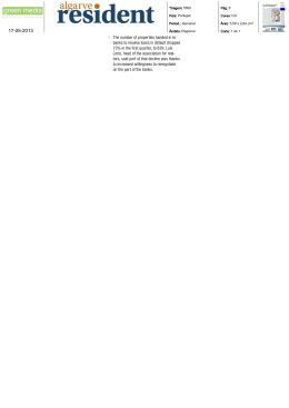
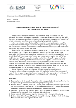
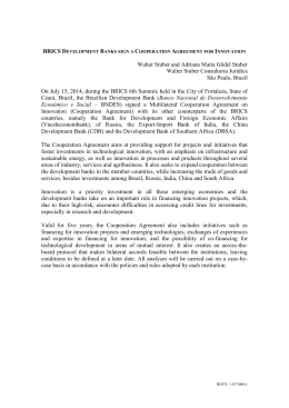
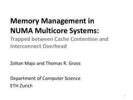
Download