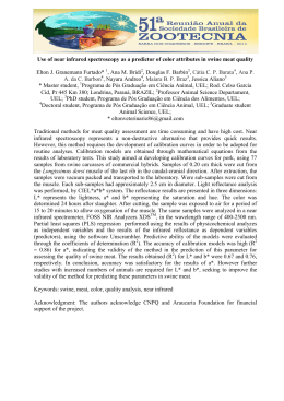
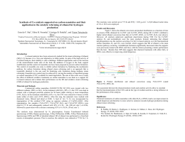
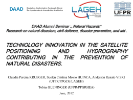
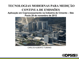
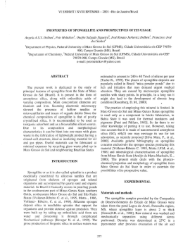
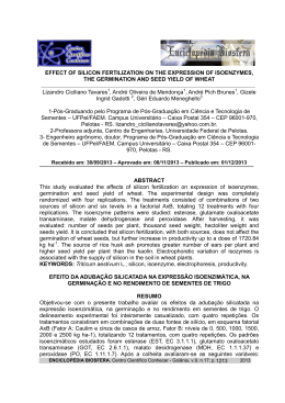
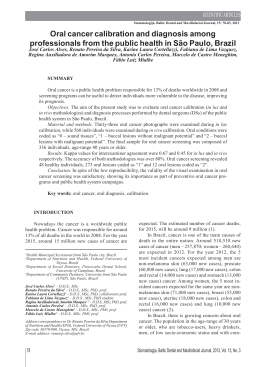
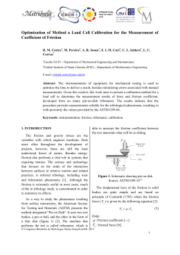
LP NET 14
100
90
80
70
T(%)
60
50
40
30
20
10
0
100
1000
10000
Lambda (nm)
Graphic 1: Relative spectral response of the Delta Ohm pyranometers.
Also the pyrgeometers are based on a thermopile. In this case, to protect the
thermopile, silicon discs are used. Silicon is transparent to wavelengths longer
than 1.1µm therefore on the inside of the window there is a filter to block radiation up to 4.5- 5 m. The silicon external surface, which is exposed to weathering, is coated with a scratch-resistant coating (DLC) to ensure strength and durability in all weather conditions. The anti-scratch coating offers the advantage
of cleaning the surface without risk of scratching the window. Graphic 2 reports
the transmission of the silicon window according to the wavelength variation:
T(%)
100
50
LP NET 14
NET IRRADIANCE METER
LP NET 14 is a 4-component net-radiometer for the measurement of the net
radiation between 0.3 m and 45 m.
The net-radiometer consists of two pyranometers (one for the measurement of
the global radiation Esw! and the other one for the measurement of the reflected
solar radiation Esw") and a pair of pyrgeometers (one for the measurement of
the infrared radiation emitted by the sky EFIR! and the other one for the infrared
emitted by the ground surface EFIR").
The LP NET 14 is equipped with a temperature sensor (NTC). The measurement
of the temperature is needed for the measurement with the two pyrgeometers,
in fact, the far infrared is derived by measuring the thermopile output and by the
knowledge of the instrument’s temperature.
The net radiometer is suitable for outdoor use in all weather conditions and
requires little maintenance.
2 Working principle
The pyranometers that make up the LP NET 14 measure the radiation for wave
lengths between 0.3µm e 3.0µm, while the pyrgeometers measure the irradiance in the spectral range between 5µm and 45µm.
The pyranometers are based on a thermopile sensor which sensitive surface
is covered by a matt black paint so to allow the instrument not to be selective
at various wavelengths. The pyranometer spectral range is determined by the
transmittance of the two glass domes type K (See fig. 1).
Radiant energy is absorbed by the thermopile black surface, creating a difference of temperature between the centre of the thermopile (hot junction) and the
pyranometer
body (cold junction). Thanks to the Seebeck effect, the difference of temperature
between hot and cold junction is converted into a Difference of Potential.
0
1
Environmental Analysis
100
Graphic 2: Transmission of the silicon window.
Radiant energy is absorbed / radiated from the surface of the blackened thermopile, creating a temperature difference between the centre of the thermopile (hot
junction) and the body of pyrgeometer (cold junction). The temperature difference between hot and cold junction is converted into Potential Difference thanks
to the Seebeck effect.
If the pyrgeometer temperature is higher than the radiant temperature of the
portion of sky framed by the pyrgeometer, the thermopile will irradiate energy
and the output signal will be negative (typical situation of clear sky) vice versa if
the pyrgeometer temperature is lower than that portion of sky framed, the signal
will be positive (typical situation of cloudy sky).
Therefore, for the calculation of the ground infrared (EFIR !), besides the thermopile output signal, is necessary to know the T temperature of the pyrgeometer,
as reported under the formula 1:
EFIR !#Eterm$%&TB4
1
Where:
Eterm = net radiation (positive or negative), measured by the thermopile [W m-2)],
the value is calculated by the sensitivity of the instrument (C) [ V/ (W m- 2)
] and by the output signal (Uemf ) from formula 2;
Eterm. =
&
30
10
Lambda (um)
Uemf
C
= Stefan-Bolzmann constant (5.6704x10⁻⁸ W m-2 K-4);
2
TB
= pyrgeometer temperature (K), obtained by the reading of the NTC (10K')
resistance. In the manual (Table 1) is reported the resistance value according to the temperature for values included between -25°C and +55°C.
The first term of the formula 1 represent the net radiation, that is to say the difference between ground infrared radiation and the pyrgeometer emission, while
the second term is the radiation emitted by an object (taken with submissiveness (=1) at TB temperature.
52
160
3 Installation and mounting of the net-radiometer for the infrared radiation
measure:
Before installing the net-radiometer you need to load the cartridge containing
silica gel crystals. The silica gel has the function of absorbing humidity present
inside the instrument; in particular climatic conditions this humidity can lead to
condensation on the inner surface of the silicon window. While loading silica gel
crystals, avoid touching it with wet hands. The operations to perform (as much
as possible) in a dry place are:
1- unscrew the six screws that fix the inner cap of the net-radiometer.
2- remove (if present) the old cartridge and the marker
3- open the envelope containing the silica gel and the marker
4- insert the cartridge in the salts-compartment
5- insert the marker so that it can easily be checked without opening the saltscompartment
6- tighten the six screws on the lid, make sure that the seal is positioned correctly.
7- the net-radiometer is ready for use
74
FIXING SHAFT
F
NG
IXI
SH
AF
T
t5IF-1/&5IBTUPCFJOTUBMMFEJOBMPDBUJPOFBTJMZBDDFTTJCMFGPSQFSJPEJD
cleaning of the silicon window. At the same time you should avoid buildings,
4 Electrical Connections and requirements for electronic reading:
tThe net-radiometer LP NET 14 does not need any power supply.
tThe instrument is equipped with two M12 8 pole connectors.
tThe optional cables end with an 8 pole connector on one side and open wires
at the other side. The cable is made in UV-resistant PTFE and is provided with
7 wires plus braid (screen), the diagram with the correspondence between
wire colours and connector poles is the following (figure 5):
Pyrgeometers
Fixing axis
Pyranometers
SILICA-GEL )
2
1
8
3
7
5
6
4
2
1
8
3
7
5
6
4
Fixed 8-pole
plug M12
Ø16
1
2
3
4
5
6
7
8
FIG. 3
trees or obstacles of any kind exceed the horizontal plane on which lies the
instrument. In case this is not possible it is advisable to choose a location
where the obstacles are lower than 10 °.
t6TVBMMZUIFJOTUSVNFOUJTQMBDFETPUIBUUIFDBCMFDPNFTPVUGSPNUIFTJEFPG
the NORTH pole, when it is used in the NORTHERN hemisphere; from the side
of the SOUTH pole when it is used in the SOUTHERN hemisphere, according
to the standard ISO TR9901 and other WMO recommendations. In any case,
it is preferable to comply with these recommendations also when the screen
is used.
t'PSBOBDDVSBUFIPSJ[POUBMQPTJUJPOJOHUIF-1/&5IBTUPCFmYFEPOBTVQport pole by using the fixing bracket.
Flying 8-pole M12 socket
FIG. 5
Connector
Function
Colour
Pyrgeometers
Pyranometers
1
Vout (+) EFIR !
Vout (+) ESW !
Red
2
Vin (-) EFIR!
Vin (-) ESW!
Blue
3
screen (
4
)
screen (
)
Screen
NOT CONNECTED
5
Vout (-) EFIR "
Vout (-) ESW "
Brown
8
Vin (+) EFIR"
Vin (+) ESW"
Green
6
NTC
NOT CONNECTED
7
NTC
Screen (
)
White
Black
Table 1: correspondence pin-function
Environmental Analysis
31
Environmental Analysis
FIG. 4
In order to obtain a measure, it is necessary to acquire simultaneously the signal
of the four thermopiles and the NTC.
To measure the output signals of the four thermopiles, the four channels have
to be connected to a millivoltmeter or a data logger. In order to fully exploit
the features of the net-radiometer, the recommended resolution of the reading
instrument is 1 V.
Moreover, it is necessary to read the NTC resistance so to determine temperature of the two pyrgeometers.
Under figure 6 the electrical connections necessary to read the signal of the four
thermopiles and the NTC are reported.
PYRGEOMETERS
Thermopile
PYRANOMETERS
Case
NTC
8
5
Thermopile
2
1
6
7
3
2
1
5
8
3
The efficiency of silica-gel crystals decreases over time with the absorption of
moisture. Typically the duration of silica gel ranges from 4 to 12 months depending on environmental conditions the instrument operates in. In order to evaluate
easily the efficiency status of the salt, within each charge there’s a marker added, to be placed at the bottom of the salt compartment so that it can be seen.
When it indicates the presence of humidity, it is necessary to replace the salts.
Hail of particular intensity or dimension may damage the silicon window, therefore, after an intense storm with hail, it is recommended to check the status of
the window.
6 Calibration and measurements:
Each pyranometer and pyrgeometer that composes the instrument is calibrated
individually
The calibration factor S is given in V/(Wm-2).
t0ODFUIFQPUFOUJBMEJGGFSFODF%%1
IBTCFFONFBTVSFEBUTFOTPSFOET&Fn
ux is obtained
through the following formula:
Ee= DDP/S
where;
Ee: indicates the radiant flux expressed in W/m²,
DDP: indicates the potential difference expressed in μV and measured by the
multimeter.
S:
indicates the calibration factor expressed in μV/(W/m²) and shown on the
net radiometer label (calibration factor is also mentioned in the calibration report).
Each net radiometer comes factory calibrated and has its own calibration factor.
FIG. 6
5 Maintenance
In order to ensure a high measurement accuracy, it is necessary to always keep
clean the silicon window and the glass domes of the net-radiometer, so the higher the frequency of cleaning is the best measurement accuracy will be. Cleaning
can be done with normal maps for cleaning photographic objectives and water,
if not possible, simply use pure ethyl alcohol. After cleaning with alcohol, it is
necessary also to clean the window again in silicon with water only.
Due to the high temperature fluctuations between day and night, it is possible
that you get some condensation inside the pyrgeometers and pyranometers (especially on the window in silicon); in this case the reading is done wrong. To
minimize condensation inside the pyrgeometers, a proper cartridge with absorbent material is inside: Silica gel.
The measurement with the two pyrgeometers ha to be performed as follows:
According to the NTC RNTC [ohm] resistance it is possible to trace the pyrgeometer temperature (Tb) back by using the formula 3:
1
= a+b∙log(RNTC)+c∙(RNTC)3
Tb
3
Where:
a=10297.2x10-7;
b=2390.6x10-7;
c=1.5677x10⁻⁷.
Temperature is expressed in Kelvin degrees.
N.B. The values between -25 ° C to +58 ° C are tabulated in Table 2, to obtain
the value in degrees Kelvin, use the appropriate conversion
Upper pyranometer
Upper pyrgeometer
Lower pyranometer
Lower pyrgeometer
32
Environmental Analysis
R_NTC
[']
103700
98240
93110
88280
83730
79440
75390
71580
67970
64570
61360
58320
55450
52740
50180
47750
45460
43290
41230
39290
37440
35690
34040
32470
30980
29560
28220
26950
T
[C]°
3
4
5
6
7
8
9
10
11
12
13
14
15
16
17
18
19
20
21
22
23
24
25
26
27
28
29
30
R_NTC
[']]
25740
24590
23500
22470
21480
20550
19660
18810
18000
17240
16500
15810
15150
14520
13910
13340
12790
12270
11770
11300
10850
10410
10000
9605
9228
8868
8524
8195
T
[C]°
31
32
33
34
35
36
37
38
39
40
41
42
43
44
45
46
47
48
49
50
51
52
53
54
55
56
57
58
R_NTC
[']
7880
7579
7291
7016
6752
6499
6258
6026
5804
5592
5388
5193
5006
4827
4655
4489
4331
4179
4033
3893
3758
3629
3505
3386
3386
3271
3161
3055
Table 2: NTC resistance values as a function of temperature.
Once the pyrgeometer temperature in Kelvin degrees and the thermopile output
signal are known Uemf [ V], irradiation EFIR! [W/m2] is obtained by the formula 1:
EFIR o=
Uemf
+T∙TB4
C
4
of clear sky. The data acquired by a data logger is then processed to obtain the
calibration factor.
To fully exploit the features of the probe LP NET 14, it is recommended to perform the calibration verification every one or two years (the choice of calibration
interval depends both on the accuracy to be achieved and on the installation
location).
7 Technical specifications
PYRANOMETERS
II° Class pyranometer according to ISO 9060
Typical sensitivity:
Impedance:
Measuring range:
Field of view:
Spectral range:
(dome transmission)
Working temperature:
PYRGEOMETERS
Typical sensitivity:
Impedance:
Measuring range:
Viewing field:
Spectral range:
(silicon window transmission)
Working temperature:
10 V/(W/m2)
33 ' * 45 '
0-2000 W/m2
2+ sr
305 nm * 2800 nm (50%)
335 nm * 2200 nm (95%)
-40 °C * 80 °C
5-10 V/(W/m2)
33 ' * 45 '
-300+300 W/m2
160°
5.5 m * 45 m (50%)
-40 °C * 80 °C
ORDERING CODES
LP NET 14: Net-radiometer equipped with:
bracket ,=16 mm length 400 mm, 2 bird spikes, 2 recharges of desiccant
(composed of 5 silica-gel cartridges and one marker), level. 2 8-pole M12
flying connectors and Calibration Report.
ACCESSORIES
LPG2: 2 Recharges composed of 2 silica gel cartridges.
CPM12AA8.5: Cable with 8-pole M12 connector, 5 meters long.
CPM12AA8.10: Cable with 8-pole M12 connector, 10 meters long.
Where:
C = pyrgeometer calibration factor [ V /(W/m2)] reported on the calibration
report;
& = Stefan-Bolzmann constant (5.6704x10⁻⁸ W m-2 K-4).
Each pyrgeometer is individually calibrated at the factory and is distinguished
by its calibration factor.
Pyrgeometer calibration is performed outdoors, for comparison with a sample
pyrgeometer calibrated by the Word Radiation Centre (WRC).
The two instruments are kept outdoors for a few days and nights in the presence
Environmental Analysis
33
Environmental Analysis
T
[C]°
-25
-24
-23
-22
-21
-20
-19
-18
-17
-16
-15
-14
-13
-12
-11
-10
-9
-8
-7
-6
-5
-4
-3
-2
-1
0
1
2
Download