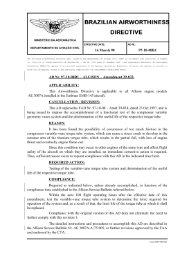
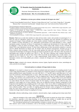
63-2585
FORD
2013-16 Fusion
L4-2.0L Turbo
D
M
F G
A
B
C
A
E
F
G
H
L
I
J
F
N
TOOLS NEEDED:
flat blade screw driver
13mm socket
10mm socket
4mm socket
ratchet
extension
4mm hex key
K
PARTS LIST:
Description
Qty.
Part #
Description
Qty.
Part #
Description
Qty.
Part #
A
HOSE CLAMP #52
2
08620
F
WASHER, M6 SPLIT LOCK ZINC
3
1-3025
K
HOSE CLAMP #56
1
08620
B
HOSE; 3-1/4" ID X 2" L
1
08690
G
WASHER; 6MM FLAT, SS
2
08269
L
AIR FILTER
1
RC-1637
C
VENT; STRT, 1/4" NPT
1
08938
H
BRACKET; 57-1532, SM."L"
1
07158
M
EDGE TRIM (35")
1
102471
D
INTAKE TUBE
1
087266
I
BOLT; M6 X 1.00 X 12MM, SS
1
07730
N
HEAT SHIELD
1
073140
E
BOLT; M6 X 1.00 X 16MM
2
07703
J
GROMMET; .875ODX.50ID
1
08063
NOTE: FAILURE TO FOLLOW INSTALLATION INSTRUCTIONS AND NOT USING THE PROVIDED HARDWARE
MAY DAMAGE THE INTAKE TUBE, THROTTLE BODY AND ENGINE.
TO START:
1. Turn off the ignition and disconnect the negative
battery cable.
NOTE: Disconnecting the negative battery cable
erases pre-programmed electronic memories.
Write down all memory settings before
disconnecting the negative battery cable. Some
radios will require an anti-theft code to be
entered after the battery is reconnected. The
anti-theft code is typically supplied with your
owner’s manual. In the event your vehicles
anti-theft code cannot be recovered, contact an
authorized dealership to obtain your vehicles
anti-theft code.
2. Lift up and remove the engine cover from the
engine.
3. Disconnect the crank case vent hose from
the factory intake tube by depressing the square
locking tab.
4. Loosen the hose clamp that secures the intake
tube to the turbo inlet.
5. Loosen and remove the bolt that secures the
intake tube to the engine.
6. Disconnect the temperature sensor electrical
connect.
NOTE: Two different types of temperature
sensors are used. See step 6a.
Continued
INSTALLATION INSTRUCTIONS
15. Install edge trim onto heat shield as shown.
NOTE: Some trimming of the edge trim will be
necessary.
6a. Some vehicles may be equipped with a twist
lock style temperature sensor.
11. Remove the temperature sensor from the
factory air box and then remove the “O” ring from
the sensor.
NOTE: The style sensors WITHOUT the bolt will
need to be rotated counter clockwise a ¼ turn
and then pulled out of the air box.
7. Unhook the EVAP tube from the clip on the
factory intake tube.
16. Install heat shield onto factory lower air box.
Snap in place using factory retaining clips.
12. Install provided grommet into K&N® intake
tube.
NOTE: On vehicles equipped with the sensor
without the bolt to secure it will need the hole
in the intake tube drilled out to ¾”id.
8. Release the two upper air box retaining clips and
then remove the complete intake assembly.
NOTE: K&N Engineering, Inc., recommends that
customers do not discard factory air intake.
17. Install K&N® intake tube into the hose and onto
the tube mounting bracket. Align with heat shield
and secure with provided hardware.
9. Install the coupling hose (08690) onto factory
turbo intake tube and secure with provided hose
clamp.
18. Install K&N® filter onto K&N® intake tube.
Secure with provided hose clamp.
13. Install the temperature sensor into the K&N®
intake tube and secure with the provided hardware.
NOTE: The quarter turn style sensor does not
use hardware to hold it in.
19. Connect crankcase vent line onto quick
connect fitting on K&N® intake tube.
10. Attach tube bracket 07158 onto engine with
provided hardware. Do not completely tighten at
this time.
14. Install provided ¼ NPT quick connect fitting
onto the K&N® intake tube.
NOTE: Plastic NPT fittings are easy to cross
thread. Install the vent fitting “hand” tight, then
turn it two complete turns with a wrench.
Continued
INSTALLATION INSTRUCTIONS
ROAD TESTING:
1. Start the engine with the transmission in neutral
or park, and the parking brake engaged. Listen for
air leaks or odd noises. For air leaks secure hoses
and connections. For odd noises, find cause and
repair before proceeding. This kit will function
identically to the factory system except for being
louder and much more responsive.
2. Test drive the vehicle. Listen for odd noises or
rattles and fix as necessary.
20. Reconnect pressure sensor electrical connector
onto sensor.
22. Reconnect the vehicle’s negative battery cable.
Double check to make sure everything is tight and
properly positioned before starting the vehicle.
23. It will be necessary for all K&N® high flow intake
systems to be checked periodically for realignment,
clearance and tightening of all connections.
Failure to follow the above instructions or proper
maintenance may void warranty.
3. If road test is fine, you can now enjoy the added
power and performance from your kit.
4. K&N Engineering, Inc., requires cleaning the
intake system’s air filter element every 100,000
miles. When used in dusty or off-road
environments, our filters will require cleaning more
often. We recommend that you visually inspect
your filter once every 25,000 miles to determine
if the screen is still visible. When the screen is no
longer visible some place on the filter element, it is
time to clean it. To clean and re-oil, purchase our
filter Recharger® service kit, part number 99-5050
or 99-5000 and follow the easy instructions.
21. Reinstall engine cover.
* FREE K&N® decal To register your warranty, please see us online at knfilters.com/register. FREE K&N® decal *
• 1455 CITRUS ST., P.O. BOX 1329, RIVERSIDE, CA., U.S.A. 92502 • TECH SERVICE 800-858-3333 • FAX 951-826-4001
• e-mail: [email protected]® • WWW: http://www.knfilters.com®
19644C
9/23/15
Download