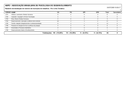
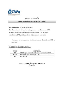
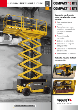
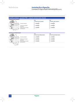
Guia Compact do UsuárioStagebox e de Instalação Userda&Compact Installation Guide Stagebox ® Soundcraft Compact Stagebox User/Installation Guide Page 1 IMPORTANTE IMPORTANT IMPORTANT Leia esse manual cuidadosamente antes de usar o unit seu equipamento pela Please read this manual carefully before using your forfor thethe first time. Please read this manual carefully before using your unit first time. primeira vez. This equipment complies with the EMC directive 2004/108/EC Thisequipamento equipment complies withconformidade the EMC directive 2004/108/EC Este está em com as diretivas EMC 2004/108/EC and LVD 2006/95/EC 2006/95/EC e and LVDLVD 2006/95/EC. This product is approved to safety standards Thisproduto product is to safety Este foiapproved aprovado pelosstandards padrões de segurança IEC 60065:2001 (Seventh Edition) +A1:2005 IEC60065:2001 60065:2001 (Seventh IEC (Sétima Edition) Edição)+A1:2005 +A1:2005 EN60065:2002 +AMD1:2006 + A11:2008 EN60065:2002 +AMD1:2006 + A11:2008 EN60065:2002 +AMD1:2006 + A11:2008 UL60065-07 UL60065-07 UL60065-07 CAN/CSA C22.2 No60065.03 + AMD01:2006 CAN/CSAC22.2 C22.2 No60065.03 No60065.03 + +AMD01:2006 CAN/CSA AMD01:2006 And EMC standards EMC standards E And padrões EMC EN55103-1:2009 EN55103-1:2009 EN55103-1:2009 EN55103-2:2009 EN55103-2:2009 EN55103-2:2009 Aviso: Qualquer modificaçãoor ouchanges alteraçãomade feita neste equipamento, a nãoexplicitly ser que expressamente aprovaWarning: AnyAny modification to this device, unless approved by by modification or changes to this device, unless explicitly approved daWarning: pela Harman, irá invalidar a licença deste made equipamento. A Operation operação deofum equipamento não licenciaHarman, will invalidate the authorisation of this device. an unauthorised invalidate the302 authorisation of this device. Operation of an unauthorised doHarman, é proibidawill conforme Seção do Ato de Comunicação de 1934, conforme emenda e Sub-parte 1 da device prohibited under Section 302302 of the Communications actact of 1934, as as amended, Parte 2isdo 47 dounder Código de Leis Federais. device isCapítulo prohibited Section of the Communications of 1934, amended, andand Subpart 1 of1 Part 2 of2 Chapter 47 47 of the Code of Federal Regulations. Subpart of Part of Chapter of the Code of Federal Regulations. NOTA: Este equipamento foi testado e está de acordo com as restrições para o equipamento digital Clas- se B, de acordo com a Parte 15 das Regras do FCC (Federal Communications Commission – Comissão NOTE: ThisThis equipment hashas been tested andand found to comply withwith thethe limits for for a Class B digital NOTE: equipment been tested found toa fornecer comply limits a Class B digital Federal de Comunicações) Estas restrições destinam-se proteção razoável contra interfedevice, pursuant to Part 15 of the FCC Rules. These limits are designed to provide reasonable rências instalações residenciais. equipamento utilizatoeprovide pode irradiar energia device,prejudiciais pursuant em to Part 15 of the FCC Rules.Este These limits are gera, designed reasonable protection against harmful in ainresidential installation. This de frequência de rádio e, seinterference não for instalado e utilizado de acordo com as instruções, pode causar protection against harmful interference a residential installation. This interferência que é prejudicial àscan comunicações por frequency rádio. No entanto, nada que nãoand ocorram equipment generates, uses and radiate radio energy and, ifgarante not installed equipment generates, uses and can radiate radio energy and, if not installed and à interferências em uma determinada instalação. Se estefrequency equipamento causar interferência prejudicial used in accordance withwith thethe instructions, maydetectado cause harmful interference to radio used in de accordance cause harmful interference radio recepção radio ou televisão, oinstructions, que pode sermay desligando e ligando o to equipamento, o usuário communications. However, there isatravés no guarantee thatthat interference willwill notnot occur in ainparticular pode tentar corrigir aHowever, interferência das seguintes medidas: communications. there is no guarantee interference occur a particular installation. If this equipment does cause harmful interference to radio or television reception, installation. If this equipment does cause harmful interference to radio or television reception, * Redirecionar ou deslocarby a antena receptora. which cancan be be determined thethe equipment off off andand on,on, thethe useruser is encouraged to try to to which determined turning by turning equipment is encouraged to try correct the interference by one or more of the following measures: * correct Aumentar distância entre equipamento o receptor. thea interference by oone or more ofethe following measures: Ligar o equipamento emreceiving uma tomada que seja de um circuito diferente daquele em que o receptor **Reorient or relocate the antenna * Reorient or relocate the receiving antenna ligado. *estiver Increase the separation between the equipment andand thethe receiver * Increase the separation between the equipment receiver **Connect the equipment into an outlet on a circuit different from that to which thethe receiver is is distribuidor ou obter ajuda de um em rádio/TV *Consultar Connecto the equipment into an outlet on técnico a circuitexperiente different from that to which receiver connected. connected. maiores detalhes *Para Consult thethe dealer or contate an experienced radio/TV technician for for helphelp * Consult dealer or an experienced radio/TV technician Harman International For further details contact Industries Ltd, Cranborne House, Cranborne Road, Potters Bar, Hertfordshire EN6 For RU further details +44(0) contact 3JN, Telefone 665000 House, Fax +44 (0)1707Road, 660742 [email protected] Harman International Industries1707 Ltd, Cranborne Cranborne Pottersemail: Bar, Hertfordshire EN6 3JN, UK Harman International Industries Ltd, Cranborne House, Cranborne Road, Potters Bar, Hertfordshire EN6 3JN, UK Telephone +44(0) 1707 665000 Fax +44 (0)1707 660742 email: [email protected] Telephone +44(0) 1707 665000 Fax +44 (0)1707 660742 email: [email protected] © Harman International Industries Ltd. 2011 ©Todos Harman International Industries Ltd.Ltd. 2011 os direitos reservados © Harman International Industries 2011 AllPeças rights reserved do projeto deste produto podem estar protegidas por patentes mundiais. All rights reserved PeçaofNothe BD10.947004 Rev1 Fev 11 Parts design of this product may be protected by worldwide patents. of the design E Parts e OE Fevereiro 2011of this product may be protected by worldwide patents. Part No.No. BD10.947004 1111 Part BD10.947004Rev1 Rev1FebFeb E&OE February 2011 AE&OE Soundcraft é uma divisão comercial da Harman International Industries Ltd. As February 2011 informações deste manual estão sujeitas a mudanças sem prévio aviso e isso não significa is um compromisso parteInternational do vendedor. A Soundcraft não é responsável Soundcraft aistrading division ofpor Harman Industries Ltd.Ltd. Information in this Soundcraft aperda trading division of Harman International Industries Information in this por qualquer ou dano decorrente do uso da informação ou qualquer manual is subject to change without notice and does not represent a commitment on theerro partpart manual is subject to change without notice and does not represent a commitment on the neste manual. ofcontido the vendor. Soundcraft shall not be liable for any loss or damage whatsoever arising from thethe of the vendor. Soundcraft shall not be liable for any loss or damage whatsoever arising from useuse of information or any error contained in this manual. of information or anymanual error contained in this manual. armazenada em um sistema Nenhuma parte desse pode ser reproduzida, de recuperação, ou transmitida de qualquer forma ou por meios, eletrônico, eléNo partpart of this manual maymay be químico, reproduced, stored in fotocópia ainretrieval system, or transmitted, in any trico, mecânico, ótico ou incluindo e gravação, para qualquer No of this manual be reproduced, stored a retrieval system, or transmitted, in any form or by any means, electronic, electrical, mechanical, optical, chemical, including photopropósito sem o consentimento expresso e por escrito da Soundcraft. form or by any means, electronic, electrical, mechanical, optical, chemical, including photocopying andand recording, for for anyany purpose without thethe express written permission of Soundcraft. copying recording, purpose without express written permission of Soundcraft. ® ® Page 2Página 2 Page 2 Harman International Industries Limited Harman International Industries Limited Cranborne House, Cranborne Road, Potters Bar,Bar, Hertfordshire, EN6EN6 3JN, UK UK Cranborne House, Cranborne Road, Potters Hertfordshire, 3JN, Tel:Tel: +44+44 (0)1707 665000 (0)1707 665000 Fax:Fax: +44+44 (0)1707 660742 (0)1707 660742 http://www.soundcraft.com http://www.soundcraft.com Soundcraft Stagebox User/Installation Guide Guia do Usuário eCompact de Instalação da Soundcraft Compact Stagebox Soundcraft Compact Stagebox User/Installation Guide Atenção: conforme lei brasileira nº 11.291, a exposição prolongada a ruídos superiores a 85dB pode causar danos ao sistema auditivo. Estes produtos podem sofrer alterações sem aviso prévio. Todas as figuras contidas neste manual são meramente ilustrativas. Cód.: 207871 Rev.: 00 - 11/12 Índice INTRODUÇÃO............................................................................................... 4 AVISOS DE SEGURANÇA............................................................................ 4 GUIA DE SÍMBOLOS DE SEGURANÇA...................................................... 4 AVISOS IMPORTANTES DE SEGURANÇA................................................. 5 AVISOS........................................................................................................................6 DESCARGA ELETROSTÁTICA (ESD).........................................................................6 TRABALHANDO COM SOM DE MANEIRA SEGURA................................ 7 GARANTIA.................................................................................................... 7 FUNÇÕES...................................................................................................... 8 Módulos Disponíveis.................................................................................................8 Fendas de Expansão.................................................................................................8 DETALHES.................................................................................................... 9 Alimentação Primária de Energia..........................................................................9 Visão Geral do Módulo de Função..........................................................................9 CONECTANDO............................................................................................12 Conexão da Compact Stagebox com os Consoles da Faixa Vi2-Vi6............... 12 Conectando a Compact Stagebox ao Vil e Consoles Si Range....................... 14 SUBSTITUINDO OS MÓDULOS E/S.........................................................15 INSTALAÇÃO DOS CARTÕES E/S D21m...............................................16 SUBSTITUINDO/LIMPANDO O FILTRO DE AR DO VENTILADOR......... 16 Guia do Usuário e de Instalação da Soundcraft Compact Stagebox Página 3 INTRODUÇÃO INTRODUCTION AVISOS DE SEGURANÇA SAFETY NOTICES Para a sua própria segurança e para evitar a invalidação da garantia, For your own safety and seção to avoidcuidadosamente. invalidation of the warranty please read leia esta this section carefully. SAFETY SYMBOL GUIDE GUIA DE SÍMBOLOS DE SEGURANÇA Forsua yourprópria own safety and toe para avoidevitar invalidation of the da warranty all todos text marked with Para segurança a invalidação garantia os textos marthese symbols should bedevem read carefully. cados com esses símbolos ser lidos com cuidado. WARNINGS AVISOS The lightning withaarrowhead symboldentro is intended alert the user O símbolo do flash raio com ponta de flecha, de um to triângulo equilátero, to the presencedeofchamar un-insulated “dangerous voltage” the prodtem a finalidade a atenção do usuário para awithin presença de “tensão perigosa” não isolada dentro carcaça domagnitude produto, cuja magnitudea pode uct’s enclosure that may be da of sufficient to constitute risk ser suficiente para representar risco de choque elétrico às pessoas. of electric shock to persons. CUIDADOS CAUTIONS OThe ponto de exclamação dentro an de equilateral um triângulo equilátero serve para alertar o exclamation point within triangle is intended to alert usuário a respeito de instruções importantes para o manuseio e a manutenção the user to the presence of important operating and maintenance (serno material escrito que acompanhathe o produto. vicing) contidas instructions in the literature accompanying appliance. NOTAS NOTES Contém informações importantes e dicas úteis a operação Contain important information and useful tips on thepara operation of your do equipment. seu equipamento. AVISO DE SEGURANÇA PARA OS FONES DE OUVIDO HEADPHONES SAFETY WARNING Contém informações importantes e dicas úteis sobre as saídas Contain important information and useful tips on headphone outputs do fone de ouvido e níveis de monitoração. and monitoring levels. AVISO SOBRE ESD A DESCARGA WARNING ELETROSTÁTICA O símbolo da mão cruzada tem a finalidade de alertar o usuário The crossed-out hand symbol is intended to alert the user to devices em relação a dispositivos sensíveis a descargas elétricas. sensitive to electrostatic discharge. Please refer to the instructions on Consulte as instruções na página 5. page 5. Página Page 4 4 Guia do Usuário e de Instalação Soundcraft Compact Stagebox Soundcraft Compact da Stagebox User/Installation Guide IMPORTANT IMPORTANT SAFETY SAFETY WARNINGS WARNINGS MPORTANT SAFETY WARNINGS THIS AVISOS IMPORTANTES DE SEGURANÇA THIS UNIT UNIT MUST MUST BE BE EARTHED! EARTHED! IMPORTANT SAFETY WARNINGS UNITESTE MUSTshould BETHIS EARTHED! Under circumstances the mains earth be disconnected from EQUIPAMENTO DEVE SER ATERRADO! Under no no THIS circumstances should the mains earth be disconnected from the the mains mains lead. lead. UNIT MUST BE EARTHED! Under no circumstances earth bethe disconnected from the mains The wires in the mains lead are coloured in accordance with following O aterramento deve ser desconectado nenhuma circunstância. Theshould wires inthe themains mainsnão lead are coloured in accordance with the thelead. following code: Under no circumstances should mains earth besob disconnected from thecode: mains lead. Earth: Green and Yellow (Green/Yellow US) Earth: Green and Yellow (Green/Yellow - US) The wires in the mains are in accordance with the following com code: Neutral: Blue --em US) A lead fiação dacoloured rede elétrica é (White colorida códigos a seguir: Neutral: Blue (White US)conformidade The wires in the mains lead are coloured in accordance withosthe following code: Earth: Green and Yellow (Green/Yellow US) Live: Brown (Black US) Aterramento: Verde e Amarelo (EUA Verde/Amarelo) Live: Brown (Black US) Earth: Green and Yellow (Green/Yellow - US) Neutral: BlueNeutral: (White - US) Azul Neutro: - Branco) Blue (EUA (White - US) Live:As Brown (Black US) Live: Marrom (EUA – -Preto) the colours of the wires in the mains lead may not As the colours ofLive: the wires in theBrown mains lead may not correspond with with the the coloured coloured markings markings identifying identifying (Black US)correspond the terminals in your plug, proceed as follows: the terminals in your plug, proceed as follows: dos fios redenot elétrica principal pode não corresponder às the marcas coloridas identificam the colours of the•Como incores the lead may correspond with the coloured markings identifying The wire which is coloured Green and must be connected to terminal in plug which • wires The wiremains which isda coloured Green and Yellow must be connected to the terminal in the theque plug which is is As theas colours of the wires in the mains leadYellow may not correspond with the coloured markings identifying terminais de sua tomada, proceda da seguinte forma: terminals in youros plug, proceed as follows: marked with the letter E or by the earth symbol. marked with the letter E or by the earth symbol. the terminals in your plug, proceed as follows: O fio de Green cor Verde eYellow Amarelo deve conectado terminal cujo plugue estiver marcado com a letra E The wire which• beser connected to no thebe terminal in the which is • is coloured The wire whichand is colouredmust Green and Yellow must connected toplug the terminal in the plug which is (Terra) ou pelo símbolo terra. marked with the letter E or by the earth symbol. •• The wire which is coloured Blue must be connected to the terminal in the plug which The wirewith which coloured besymbol. connected to the terminal in the plug which is is marked marked with with marked theisletter E or Blue by themust earth the letter N. the letter N. O fio queBlue estiver na cor Azul deve ser ao terminal no plugue estiver with marcado com a letra N. The wire which• must be connected toconectado thebe terminal in thetoplug which que is in marked • is coloured The wire which is coloured Blue must connected the terminal the plug which is marked with the letter N. •• The wire is The letter wire which which is coloured coloured Brown Brown must must be be connected connected to to the the terminal terminal in in the the plug plug which which is is marked marked the N. deverá • Owith fio Marrom ser conectado ao terminal no plugue que estiver marcado com a letra L. the letter L. with the letter L. Estes códigos de cores deverão serare seguidos cuidadosamente o plugue for trocado. The wire whichEnsure is coloured Brown must be connected to the terminal thetose plug which marked that these colour codings carefully in event of being thatwire these colour codings are followed followed carefully ininthe the event of the the isplug plug being changed. •EnsureThe which is coloured Brown must be connected the terminal in the plugchanged. which is marked with the letter L. with the letter L. A unidade de alimentação interna não contém peças reutilizáveis. Todos os sure that these colour codings are followed carefully infollowed the ofde theenergia plug being changed. internal power supply unit contains no user serviceable parts. Refer all to The internal power supply unitevent contains no user serviceable parts. Refer all servicing servicing to aa Ensure thatThe these colour codings carefully the event of the plug changed. reparos que se fizeremare necessários deverãoinser encaminhados a umbeing profissional qualificado e qualified service engineer, through the appropriate Soundcraft dealer. qualified service engineer,pelo through the appropriate Soundcraft dealer. recomendado distribuidor daall Soundcraft. The internal power The supply unit contains no user serviceable parts. Refer servicing to a all servicing to a internal power supply unit contains no user serviceable parts. Refer qualified service engineer, through the appropriate Soundcraft dealer. qualified service engineer, through the appropriate Soundcraft dealer. DESCARGA ELETROSTÁTICA ELECTROSTATIC DISCHARGE (ESD) ELECTROSTATIC DISCHARGE (ESD) (ESD) Many semiconductor components are to The Many semiconductor components are sensitive sensitive to electrostatic electrostatic discharge (ESD). (ESD). The lifespandeof of Muitos componentes semicondutores são sensíveis a descarga discharge eletrostática (ESD). O lifespan tempo ECTROSTATIC DISCHARGE (ESD) ELECTROSTATIC DISCHARGE (ESD) assemblies containing such components can be drastically reduced by improper handling vida dos conjuntos quesuch contêm tais componentes poderá serreduced reduzidobydrasticamente se houver assemblies containing components can be drastically improper handling Many semiconductorduring components are sensitive to electrostatic discharge (ESD). The lifespan of maintenance and repair. Please observe the following rules when handling ESD sensimanuseio inadequado durante a manutenção e o reparo. Observe as regras a seguir ao manu-of during maintenance and repair. Please observe the following rules when handling ESD sensiMany semiconductor components are sensitive to electrostatic discharge (ESD). The lifespan assemblies containing such components can be drastically reduced by improper handling tive components: sear os componentes a descarga eletrostática: tive components: assemblies containing sensíveis such components can be drastically reduced by improper handling during maintenance and repair. Please observe the following rules handling ESD sensi•• ��� sensiti�e com�onents should only be stored and trans�orted in the �acking material s�ecifis�ecifi �� Os componentes sensíveis a descarga eletrostática somente devem ser armazenados e transportados • ��� sensiti�e com�onents should only be stored and trans�orted in the �acking material s�ecifis�ecifi during maintenance and repair. Please observewhen the following rules when handling ESD sensitive components: cally provided for this purpose. na embalagem quethis é fornecida cally provided for purpose.especificamente para esta finalidade. tive components: ��� sensiti�e•• com�onents should only be stored and trans�orted in assemblies, the �acking material s�ecifis�ecifi � enviados When performing a repair by replacing the removed assembly must be sent Ao executar reparos pela substituição decomplete conjuntos completos, estes deverão ser des�ecifivolta ao Whensensiti�e performing a repair byshould replacing complete assemblies, the removed assembly must be sent • ��� com�onents only be stored and trans�orted in the �acking material s�ecifi � cally provided for this purpose. back to the supplier in the same packing material in which the replacement assembly was shipped. fornecedor na mesma embalagem em que o produto substituto foi enviado. Se este não for o caso, back to the supplier in the same packing material in which the replacement assembly was shipped. cally provided for this purpose. When performing repair bysolicitação replacing assemblies, theaaserá removed assembly be and sent IfWhen not the case, any claim for possible refund will be void. de reembolsos considerada nula. If this this should should not be be thepossíveis case, any claimcomplete for possible refundthe willmust be null null and void. must be sent • aqualquer performing a complete repair by replacing assemblies, removed assembly back to the supplier in the same packing material in which the replacement assembly was shipped. Componentes desembalados e sensíveis a descarga eletrostática só devem ser manuseados •• Unpacked ESD sensitive components should only be handled in ESD protected areas e.g. • Unpacked ESD sensitive components should only be handled in ESD protected areas (EPA, (EPA, e.g.áreas back to the supplier in the same packing material in which the replacement assembly was em shipped. If this should not beprotegidas the case, any claim for a possible refund will be null and void. (por exemplo, áreas de serviços, de reparos ou bancadas) e ser tocadas somente por pessoarea for field ser�ice, re�air or ser�ice bench) and only be touched by �ersons wearing a wristlet field ser�ice, re�air or any ser�ice bench) and only refund be touched �ersons wearing a wristlet Ifarea thisfor should not be the case, claim for a possible will bebynull and void. Unpacked ESD components should only be handled in ESD protected areas al portando braceletes conectados ao de reparos oue.g. da bancada por equipment um resistor connected to ground potential of the repair or service bench aa protected series resistor. connected to the the ground potential ofaterramento the repair orpotencial service bench by(EPA, series resistor. The equipment • sensitive Unpacked ESD sensitive components should only be handled in by ESD areasThe (EPA, e.g. em série. O equipamento disponibilizado para reparos ou serviços, bem como todas as ferramentas area for field ser�ice, re�air or ser�ice bench) and only be touched by �ersons wearing a wristlet to be repaired or serviced as well as all tools and electrically semi-conducting work, storage, and to be repaired or serviced as well as all tools and electrically semi-conducting work, storage, and e area for field ser�ice, re�air or ser�ice bench) and only be touched by �ersons wearing a wristlet todo trabalho de semicondutores elétricos, armazenamento e tapetes também deverão estar conecconnected to the ground potential of the or service by or a series resistor. The floor should also be connected this ground �otential. flooromats mats should alsorepair bepotential connected tobench this ground �otential. connected to the ground of to the repair service bench by aequipment series resistor. The equipment tados a este aterramento potencial. to be repaired•• or serviced as well as all tools and electrically semi-conducting work, storage, and The terminals of ESD sensitive components must not come in uncontrolled contact electroThe terminals of ESD sensitive components must not come in uncontrolled contact with electroto be repaired or serviced as well as all tools and electrically semi-conducting work,with storage, and • also Os terminais de componentes sensíveis a descarga eletrostática não devem entrar em contato não floor mats should be connected to this ground �otential. statically chargeable or metallic surfaces (voltage puncture, discharge shock hazard). statically metallic surfaces (voltage floor matschargeable should alsoorbe connected to this groundpuncture, �otential.discharge shock hazard). supervisionado com superfícies metálicas eletrostaticamente carregáveis (punçãodue de to tensão, risco The terminals••of ESD components must not comened inouuncontrolled contact with electroTo �re�ent the com�onents from undefi undefined transient and �ossible damage inadmis� inadmisTosensitive �re�ent the com�onents from undefi undefined ned transient stress and �ossible damage inadmis� inadmisThe terminals of ESD sensitive components must notstress come in uncontrolled contactdue withtoelectrode porsurfaces descarga). statically chargeable orchoque metallic (voltage puncture, shock hazard). sible voltages or currents, electrical connections should only established sible voltages or compensation compensation currents, electrical connections should shock only be be established or or sepasepastatically chargeable or metallic surfacesdischarge (voltage puncture, discharge hazard). • A fim de preservar os componentes contra estresse transiente e possíveis danos devidos a tensões To �re�ent the• com�onents from undefi undefined ned transient stress and �ossible damage due to inadmis� inadmisrated when the equipment is switched off and after any capacitor charges have decayed. rated whenthe thecom�onents equipment isfrom switched after any capacitor chargesdamage have decayed. To �re�ent undefioff undefined nedand transient stress and �ossible due to inadmisinadmis� inadmissíveiscurrents, ou correntes de compensação, as conexões elétricas somente devem ser estabelecidas sible voltages or compensation electrical connections should only be established or sepasible voltagesquando or compensation currents, electrical connections should only be established or sepaou separadas equipamento estiver desligado ehave depois que as cargas de capacitador tiverem rated when the equipment is switched offoand after any capacitor charges decayed. rated when the equipment is switched off and after any capacitor charges have decayed. Soundcraft Compact Page decaído. Soundcraft Compact Stagebox Stagebox User/Installation User/Installation Guide Guide Page 55 undcraft Compact Stagebox User/Installation Guide Guia do Usuário e de Stagebox Instalação da Soundcraft Compact Soundcraft Compact User/Installation Guide Stagebox Page 5 Página Page 5 WARNINGS WARNINGS AVISOS •• • •• Read Read these these instructions. instructions. Leia o manual de instruções. Keep Keep these these instructions. instructions. •• • •• Heed atento all warnings. Fique a todos os avisos. • • •• • ••• ••• •• Guarde o manual de instruções. Heed all warnings. Follow all instructions. Follow all instructions. Siga todas as instruções. Clean the apparatus only with a dry cloth. Clean othe apparatus only withcom a dry Limpe equipamento apenas umcloth. pano seco. Do install near heat such as heat resistors, stoves, apparatus Não instale perto deany aparelhos que geram tais como radiadores, de aquecimento, foDo not not install near any heat sources sources suchcalor as radiators, radiators, heat resistors,registros stoves, or or other other apparatus (including am�lifiers) that �roduce heat. gões ou outros (incluindo amplificadores). (including am�lifiers) that �roduce heat. Do block any ventilation in accordance with instructions. Não bloqueie deopenings. ventilação.Install Instale acordo com as the instruções do fabricante. Não utilize Do not not block as anyaberturas ventilation openings. Install inde accordance with the manufacturer’s manufacturer’s instructions. este aparelho perto de água. Do Do not not use use this this apparatus apparatus near near water. water. • •• Leve sempre em consideração os objetivos de segurança do plugue polarizado ou aterrado. Um plug Do the safety purpose of the polarized or grounding type plug. AA polarized plug has Do not not defeat defeat purpose the uma polarized orlarga grounding plug.Um polarized plugaterramenhas two two polarizado tem the duassafety lâminas, sendoofque é mais do quetype a outra. plugue com blades with one wider than the other. A grounding type plug has two blades and a third grounding blades one widere than the de other. A grounding type plug hasoutwo bladespino and são a third grounding to possuiwith duas hastes um pino aterramento. A lâmina larga o terceiro fornecidos para prong. The wide blade or the third prong are provided for your safety. When the provided plug does prong. The wideQuando blade or the third fornecido prong arenão provided for your safety. When the provided plug does sua segurança. o conector se ajustar à sua tomada, consulte um eletricista para not fit outlet, consult an anot substituição daoutlet, tomada obsoleta. fit into into your your consult an electrician electrician for for re�lacement re�lacement of of the the obsolete obsolete outlet. outlet. ••• Protect power cord on or particularly at convenience receptaProteja cabo de alimentação parawalked que este seja pisado ou prensado, particularmente conecProtectothe the power cord from from being being walked onnão or pinched pinched particularly at plugs, plugs, conveniencenos receptacles and the point where they exit from the apparatus. tores, nos the receptáculos de they conveniência, ponto onde eles saem do equipamento. cles and point where exit from ou theno apparatus. ••• ••• Only attachments/accessories by manufacturer. Utilize somente conexões/acessórioss�ecified especificados fabricante. Only use use attachments/accessories s�ecified by the thepelo manufacturer. Desligue o equipamento se ocorrerem ou quando for utilizar porperiods longos of períodos. Unplug this apparatus during lightningraios storms or whennão unused for long time. Unplug this apparatus during lightning storms or when unused for long periods of time. Todos osser�icing reparos devem ser feitos apenas por pessoal especializado. Será necessário •• • Refer all to qualified ser�ice �ersonnel. �er�icing isis required when the Refer all ser�icing to qualified ser�ice �ersonnel. �er�icing required when the a��araa��araprocurar a assistência técnica quando o produto tiver sido danificado de alguma maneitus has been damaged in any way such as power-supply cord or plug is damaged, liquid tus has been damaged inoany way ou such as power-supply cord or plug is damaged, liquid ra. been Por exemplo, quando plugue o into cabothe estiverem estragados, quandohas líquidos ou has spilled or objects have fallen apparatus, the apparatus been has been spilled or objects have fallen into the apparatus, the apparatus has been objetos tiverem caído sobre does o equipamento, quando este tiver sido exposto à chuva ou exposed exposed to to rain rain or or moisture, moisture, does not not operate operate normally normally or or has has been been dropped. dropped. umidade ou quando não estiver funcionando normalmente ou tiver caído. ••• • •• • Use only with stand, tri�od, or by or Utilize carrinho, bancada, tripé, suporte ous�ecified mesa especificado pelo fabricante Use onlysomente with the theocart, cart, stand, tri�od, bracket bracket or table table s�ecified by the the manufacturer, manufacturer, or sold with the apparatus. When the cart is used, use caution when moving the cart/apou vendidos com o equipamento. Quando um carrinho for utilizado, tenha cuidado ao sold with the apparatus. When the cart is used, use caution when moving the cart/apparatus from tip-over. movê-locombination junto com o to equipamento, tombamento. paratus combination to avoid avoid injury injurypara fromevitar tip-over. Não coloque objetos com fogo, tais como velas acesas, sobre o equipamento No No naked naked flame flame sources, sources, such such as as lighted lighted candles candles or or cigarettes cigarettes etc., etc., should should be be �laced �laced on on the the a��aa��aratus. Aviso: Para reduzir o risco de incêndio ou choque elétrico, não exponha o aparelho à chuva ou umidaratus. •• de. Não expor o aparelho a goteiras ou respingos e não coloque nenhum a��aratus objeto que contenha líquidos, Warning: To reduce the Warning: To sob reduce the risk risk of of fire fire or or electric electric shock, shock, do do not not ex�ose ex�ose this this a��aratus to to rain rain or or moisture. moisture. como vasos o aparelho. �o not ex�ose the a��aratus to dri��ing or s�lashing and do not �lace objects filled with liquids, • such as the Este contém peças reutilizáveis. Todos os reparos que se fizerem necessários devesuchequipamento as vases, vases, on onnão the apparatus. apparatus. rão ser encaminhados a um profissional qualificado e recomendado pelo distribuidor da Soundcraft. •• • •• • •• • •• �o not ex�ose the a��aratus to dri��ing or s�lashing and do not �lace objects filled with liquids, This This unit unit contains contains no no user user ser�iceable ser�iceable �arts. �arts. Refer Refer all all ser�icing ser�icing to to aa qualified qualified ser�ice ser�ice engineer, engineer, A ventilação appropriate não deve ser obstruída ao cobrir as entradas de ventilação com itens como jornais, toathrough through the the appropriate Soundcraft Soundcraft dealer. dealer. lhas de mesa, cortinas, etc. Ventilation should not be impeded by covering the ventilation openings with items such as newspa- Ventilation should not be impeded by covering theestar ventilation such as O plugue é ocloths, dispositivo para desconexão. Ele deve sempreopenings acessívelwith paraitems que possa sernewspaprontapers, table curtains etc. pers, table cloths, curtains etc. mente utilizado. The disconnect device is the mains plug; it must remain accessible so as to be readily operable in disconnect que device mains plug; it must do remain accessible so as to bepela readily operableouin ÉThe recomendado todaisathe manutenção e reparos produto sejam executados Soundcraft use. use. por seus agentes autorizados. A Soundcraft não pode aceitar qualquer responsabilidade por qualquer It is recommended thatpor all assistência, maintenancemanutenção and serviceou onreparo the product should be carried by perda ou dano causado realizado por pessoal nãoout autorizado. It is recommended that all maintenance and service on the product should be carried out by Soundcraft Soundcraft or or its its authorised authorised agents. agents. Soundcraft Soundcraft cannot cannot accept accept any any liability liability whatsoever whatsoever for for any any loss loss or damage caused by service, maintenance or repair by unauthorised personnel. or damage caused by service, maintenance or repair by unauthorised personnel. Page 66 Page Página 6 Soundcraft Compact Stagebox User/Installation Guide Soundcraft Compact da Stagebox User/Installation Guide Guia do Usuário e de Instalação Soundcraft Compact Stagebox TRABALHANDO SOM DE MANEIRA WORKINGCOM SAFELY WITH SOUND SEGURA Embora este console não possa sonsany até noise que osuntil seusyou sinais alimentados, tem, no entanAlthough your new unitreproduzir will not make feedsejam it signals, it has theelecapability to produce to, a capacidade de produzir sons que, se forem monitorados através de sistema PA (public address; sistema sounds which when monitored through a PA system or headphones can damage hearing over time. de reforçoThe de table som) below ou de fones de from ouvido, vir a ser Safety prejudiciais depois de algum tempo. A tabela abaiis taken thepodem Occupational & Health Administration directive on Occupational xo foi tirada das diretrizes da Administração de Segurança e Saúde Ocupacionais sobre exposições a ruídos noise exposure (1926.52): ocupacionais (1926.52): PERMISSIBLE NOISE EXPOSURE XPOSIÇÃO E TOLERÁVEL RUÍDOS DURATION PERADAY, HOURS 8 8 6 6 4 4 3 3 2 2 1.5 1.5 1 1 0.5 <0.25 0.5 <0.25 RESPOSTA LENTA dBASLOW AO NÍVEL DO SOM SOUND LEVEL dBA RESPONSE 90 90 92 92 95 95 97 97 100 100 102 102 105 105 110 115 110 115 A conformidade com estas diretrizes irá minimizar o risco de danos à audição causados por longos períodos Conforming to this directive will minimise the risk hearing caused bybaixo long olistening de exposição. Uma regra simples a seguir é que quanto maisoftempo se damage fica ouvindo, mais volume periods. A simple rule tocuidado follow isaothe longer you lower the manipulando average volume shouldque be.você não médio deve ser. Tenha trabalhar comlisten áudiothe – se estiver controles compreende (o que fazemos estamos certifique-se controls de que monitores Please taketodos carenós when workingquando with your audioaprendendo), - if you are manipulating which youestão don’t undercom o volume quewe seus sãomake sua principal ferramenta de trabalho, cuideRemember deles e standbaixo. (whichLembre-se we all do de when areouvidos learning), sure your monitors are turned down. that eles cuidarão de você. Importante: faça experiências para descobrir como cada parâmetro afeta o som. Isto your ears are the most important tool of your trade, look after them, and they will look after you. ampliará Most a suaim�ortantly criatividade�edon’t ajudará você a to obter os melhores resultados. be afraid ex�eriment to find out how each �arameter affects the sound � this will extend your creativity and help you to get the best results. A impedância recomendada para fones de ouvido é de 50-600 ohms. Recommended headphone impedance is 50-600 ohms. GARANTIA 1. 2. 3. 4. 5. 6. 7. A Soundcraft é uma divisão comercial da Harman International Industries Ltd. Usuário Final significa a pessoa que primeiro coloca o equipamento em uma operação regular. Distribuidor é a pessoa além da Soundcraft (se houver) dos quais o Usuário Final comprou o equipamento, desde Soundcraft is a trading para division Harman International Industries que1.tal pessoa esteja autorizada os of propósitos da Soundcraft ou seusLtd. distribuidores credenciados. Equipa�nd User means the �erson whocom first �uts equi�ment into regular o�eration. mento significa o equipamento fornecido essethe manual. Dealer means the person thanda Soundcraft (if any) from whom the EndaoUser purchased theapresentar Equipment, provided Se dentro do período de doze mesesother a partir data de entrega do Equipamento Usuário Final se person is de authorised fordefeituosos this purposee/ou by Soundcraft its accredited defeito por such razãoa somente materiais falhas na or produção a umaDistributor. extensão em que a eficácia e/ Equipment the equipmentafetada suppliedowith this manual. ou capacidade de usomeans seja materialmente Equipamento ou o componente defeituoso deve ser retornado If within the perioda Soundcraft of twelve months fromas thecondições date of delivery of othe Equipmentou to othe End User itreparará shall prove para2.o Distribuidor ou para e sujeito a seguir Distribuidor Soundcraft ou defective only of faulty materials and/or workmanship such an extent that the effectiveness usability thereof substituirá by os reason componentes defeituosos. Qualquer componente to substituído se tornará propriedade daand/or Soundcraft. is materially affected the Equipment or theserá defective component should be pelo returned to theFinal Dealer or to Soundcraft and Qualquer Equipamento ou componente retornado feito com o risco assumido Usuário enquanto em subject following conditions the Dealer eoraSoundcraft repair or replace the defective components. Any compotrânsito (tanto paratoothe Distribuidor ou para Soundcraft) postagemwill deve ser pré-paga. nents replaced will become Esta garantia será válida somente se:the property of Soundcraft. Any Equipment or component will be the risk of the End User whilst in transit (both todaand from the Dealer a)o 3. Equipamento foi instalado de formareturned apropriada de at acordo com as instruções contidas no manual or Soundcraft) and postage must be prepaid. Soundcraft; e warranty only be available if: ou o Distribuidor dentro de 14 dias do defeito que apareceu; e b)o 4. UsuárioThis Final tenha shall notificado a Soundcraft the Equipment has been properly installed in accordance with instructionsque contained in Soundcraft’s c)ninguém,a)além dos representantes autorizados da Soundcraft ou do Distribuidor tiver efetuado qualquermanual; and b) the Userajustes has notified �oundcraft ou or the �ealernowithin 14 days ofe the defect a��earing; and substituição de�nd peças, de manutenção reparos Equipamento no persons other than authorised representatives the Dealer havepela effected any replacement of parts d)o Usuárioc)Final tiver utilizado o Equipamento somente paraofosSoundcraft propósitosorrecomendados Soundcraft, maintenance adjustments or repairs to que the Equipment; andacordo com as especificações da Soundcraft e apenas com os acessórios de funcionamento estiverem de d) acordo, the End em Usertodos has used the Equipment only for such purposes as Soundcraft recommends, with only such operating sempre de os aspectos, com as recomendações da Soundcraft. su��lies meetresultado �oundcraft’s s�ecifications and otherwise in all res�ects in accordance �oundcraft’s Defeitos que surjamascomo do listado a seguir não serão cobertos por essa Garantia: Falha ou negli-recommendations. gência no manuseio, influência química, eletro-química ou elétrica, danos acidentais, Força Maior, negligência, 5. Defects as controle a result ofdothe are not covered by this Warranty: faulty or negligent handling, chemical or deficiência na redearising elétrica, ar following condicionado e da umidade. electrical influences, damage, O benefícioelectro�chemical dessa Garantia or não pode ser atribuídoaccidental pelo Usuário Final.Acts of God, neglect, deficiency in electrical �ower, air�conor humidity control. Os Usuáriosditioning Finais, que são consumidores, devem notar que seus direitos sob essa Garantia são adições e não 6. qualquer The benefit of this que Warranty maysido not adquiridos be assignedpelo by the �nd User. afeta outro direito tenham vendedor do Equipamento. WARRANTY 7. End Users who are consumers should note their rights under this Warranty are in addition to and do not affect any other rights to which they may be entitled against the seller of the Equipment. Soundcraft Stagebox User/Installation Guide Guia do Usuário e deCompact Instalação da Soundcraft Compact Stagebox Página 7 Page 7 RECURSOS Compact Stagebox é ideal para quem já é proprietário dos consoles da série Vi, por ser um método eficiente em termos de custos para a expansão dos recursos de entrada pela expansão em até 96 entradas analógicas de microfone/linha, ou como parceiro para as faixas Vi1 e Si de consoles, que proporcionam um recurso remoto de entradas/saídas eficiente em termos de custos, em conjunção com os cartões opcionais de interface MADI, disponíveis para esses consoles. O Soundcraft Compact Stagebox oferece uma alta densidade de conexões E/S em apenas 178 mm (7 pol.) (4U) de espaço no rack. A unidade modular é completamente configurável, mas é oferecida com uma configuração padrão de 32 entradas de mic/linha, 8 saídas de linha, 4 x 2 canais de saídas AES/EBU e 2 fendas de expansão para os cartões padrão Studer D21m E/S. A D21m é a arquitetura I/O tanto para Studer como para sistemas digitais de mixagem Soundcraft e permite conexão com os formatos mais populares, incluindo CobraNet®, Aviom A-Net®16, EtherSound®, ADAT e RockNet®. A interface de gravação A MADI também pode ser ajustada nas fendas de expansão. É possível equipar a Compact Stagebox com módulo adicional 16 mic/line input XLR ao invés do módulo de saída, permitindo 48 entradas. Neste caso, saídas analógicas ou AES ainda podem ser obtidas em conectores tipo D, através de cartões D21m instalados nas fendas de expansão. Assim como a flexibilidade da interface do cartão de opção D21m, a Compact Stagebox utiliza o mesmo módulo I/O encontrado no console Soundcraft Vi1. Como resultado, é possível mover ou compartilhar módulos entre console e stagebox, se for necessária uma configuração diferente de E/S em Vi1 ou stagebox. Por exemplo, o cartão de saída de 8 linhas de saída/AES da stagebox poderia ser instalado para o console Vi1, em lugar de um cartão de saída de linha de 16 canais. Alternativamente, o módulo de entrada mic pode ser substituído por módulos de saída se for preciso um grande número de saídas. Ao inserir cartões nas fendas de expansão, deve-se observar que a capacidade máxima de entrada e de saída da Compact Stagebox é limitada pela conexão do console MADI com 64 entradas/64 saídas. A Compact Stagebox é conectada ao host console usado ou Cat-5 ou fibra óptica MADI, da mesma forma que os maiores 64 mic/line Vi6 Stagebox conectado, e compartilha a mesma capacidade de cabo do MADI. A unidade vem completa com dois suprimentos redundantes gêmeos de alimentação, refrigeração por ventilador controlado termostaticamente e completa monitoração de status LED. Uma interface GPIO de oito canais é fornecida também. Módulos Disponíveis • • • 16 x entradas de mic/linha (A947.043000SP) 16 x saídas de linha (A947.043500SP) 8 x saídas de linha + 4 x 2-canais de saídas AES/EBU (A947.043700SP) Fendas de Expansão Estes podem ser utilizados para um * ou dois dos seguintes cartões padrão E/S Studer D21m: • Entradas de linha de 8 canais (RS2425SP) • saídas de linha de 8 canais (RS2424SP) • * 8 x entradas e saídas AES de 2 canais (RS2422SP) entradas de mic/linha de • 4 canais com 4 x saídas diretas (RS2423SP) • * MADI óptico/multimodal de 64 canais (RS2426SP) ou Cat-5 (RS2409SP) • entradas e saídas ADAT de 16 canais (RS2360SP) • * entradas e saídas TDIF de 16 canais (RS2564SP) • saídas Aviom A-Net® de 16 canais (RS2497SP) • entradas e saídas CobraNet® de 32 canais (RS2496SP) • *# entradas e saídas EtherSound® de 64 canais • *# entradas e saídas RockNet® de 64 canais • deembedder SDI de 16 canais (RS2552SP) • decodificador Dolby® E de 16 canais (RS2553SP) # Disponível somente a partir de fabricantes terceirizados ou distribuidores. Entre em contato com www.digigram.com para conhecer as opções EtherSound® e www.riedel.net para conhecer as opções RockNet®. Página 8 Guia do Usuário e de Instalação da Soundcraft Compact Stagebox Visão Front Frontal View Rear View Vista Traseira DETALHES DETAILS A Compact Stagebox requer a utilização de um cartão padrão D21m MADI na fenda de cartão opcional Vi ou Contém Stagebox 3 fendas para módulos E/S, 2 fendas para módulos TheSi.Compact requires the addition of a standard D21mopcionais MADI cardE/S to D21m the Vi eoroSicartão optionD21m card MADI que proporciona conexão Compact Stagebox com o console. As fendas sãoand rotuladas de cima slot. ItHD, contains 3 slots for aaudio I/O da modules, 2 slots for optional D21m I/O modules the D21m a baixo A/C/E para os módulos E/S e K/L para as fendas opcionais de cartão D21m. Estas referências com MADI HD card providing the Compact Stagebox-to-console connection. Slots are labeled from top to botrótulos são utilizadas pelo sistema de correção quando o usuário desejar corrigir os conectores para canais tom A/C/E for I/O modules and K/L for the optional D21m card slots. These labeling references are used de entrada ou busses de saída. by the patching system when the user wishes to patch the connectors to input channels or output busses. Alimentação Primária de Energia Os conectores de suprimento primário de alimentação estão localizados no painel traseiro. Ambos os supriPrimaryprimários Power de Supply mentos alimentação se conectam às entradas IEC através das suas chaves de força e proporThe primary power supply are located on the rear BothVprimary supplies connect cionam uma entrada CA deconnectors alcance completo, convertendo 100panel. para 240 CA parapower 24 V CC. A Compact to the IECtem inlets via their power switches and provide a full range AC inlet,proporcionando converting 100redundância to 240 V ACpara to Stagebox normalmente instalados dois suprimentos de alimentação, 24 V �C. The Com�act �tagebox is normally fitted with two �ower su��lies, �ro�iding redundancy for those atender às necessidades. requiring it. Visão Geral da Função do Módulo Normalmente, dois módulos de entrada mic/linha e um módulo de saída linha/AES são instalados, totalizando 32 entradas e 16 saídas. No entanto, mais módulos de entrada ou de saída, até um máximo de 3 móduModule Function Overview los, totalizando 48 entradas ou saídas, podem ser instalados. Normally two mic/line in�ut and one line/A�� out�ut modules are fitted, gi�ing 32 in�uts and 16 out�uts. However, more input or output modules, up to a maximum of 3 modules giving 48 inputs or outputs, can be fitted. Guia do Usuário e de Stagebox InstalaçãoUser/Installation da Soundcraft Compact Soundcraft Compact Guide Stagebox Page 9 Página Input Modules Input modules handle 16 x mic/line amp, phantom power and A-to-D converter. An LED per input indiMódulos de the Entrada cates whether phantom power is activated. Os módulos de entrada comportam 16 x amplificador mic/linha, alimentação fantasma e conversor de A-para-D. Uma entrada por LED indica se a alimentação fantasma está ativada. Output Modules Módulos dedifferent Saída output module types available, both handling 16 outputs in total. In the standard There are two Há dois tipos diferentes módulo de 8 saída disponíveis, ambos saídas no total. Na conficonfiguration, an out�utde module with x ��to�A con�erters andcomportando electronically16 balanced line out�uts as guração padrão, são instalados um módulo de saída com conversores 8 x D-para-A e saídas de linha balanwell as 8 A��/�BU out�ut channels is fitted. An all�analogue line out�ut module with 16 electronically ceadas eletronicamente, bem comoavailable. 8 canais de AES/EBU. de which saída de balanced line outputs is optionally Thesaída modules have Um a setmódulo of relays willlinha mutetotalmente the outputs analógica com 16 saídas de linha balanceadas eletronicamente está disponível opcionalmente. Os módulos if the power fails. têm um conjunto de relés que emudecem as saídas se faltar energia. Indicadores de Status de LED LED Status Indicators Indicadores de status de LED estão disponíveis para as vias de alimentação, os módulos E/S, o ventilador e Status indicator LEDs are available for power rails, IO modules, fan and temperature alarm, and a RECONo alarme da temperatura e um botão RECON-FIG que deverá ser pressionado depois que a configuração do FIG button that must be �ressed after the card configuration has been changed. cartão for alterada. Cartão de Conexão MADI HD MADI HD Link Card Este cartão fornece as conexões de áudio e de controle para o console através de um Cat-5 ou de uma This card provides the audio and control connections to the console through either a Cat-5 or an Opticalconexão MADI de fibra ótica. O cartão MADI correspondente no console transmite o relógio para a Compact fibre MA�Iem link. The corres�onding MA�I card in the console transmits theserclock for the Com�act Stagebox direção à corrente MADI. A segunda entrada no cartão pode utilizada para fornecer�tagebox uma down the MADI stream. The second input on the card can either be used to provide a redundant connecconexão redundante para o console ou para se conectar a um segundo sistema, se dois consoles forem utilition topara the console, or to connect to a second system if two consoles are used for a monitor/FOH configuzados uma configuração monitor/FOH (Zona de Recepção; auditório). ration. The MADIMADI card indica indicates its do clock with the ‘LOCK’ LED aontrava the LED card.noAncartão. RS422Uma linksaída output also O cartão status seustatus próprio relógio, utilizando deisconexão fitted, of R�422 data �iadados a ‘�i�eline’ MA�I stream a corres�onding RS422allowing tambémtransmission é instalada, permitindo que os RS422within sejamthe transmitidos via from ‘tubulação’ dentro da port on the console’s cardporta for remote RS422 control. (This feature is supported Vi-Series concorrente MADI, a partirMADI de uma correspondente no cartão MADI do console para o by controle remoto soles only). RS422. (Este recurso é suportado somente pelos consoles da série Vi). For single cable operation: front panel toggle switch mustnobepainel set todianteiro either ‘MAIN’ orestar ‘AUX’, Para funcionamento de cabo The único: O sensor de duas posições deverá depending on which socket is being used. de qual soquete estiver sendo utilizado. configurado para ‘MAIN’ ou ‘AUX’, dependendo For dual cable (redundant) frontO panel switch mustno bepainel set todianteiro ‘RED’ Para funcionamento de cabo operation: redundanteThe duplo: sensortoggle de duas posições mode. estar no modo ‘RED’ (vermelho). deverá Consulte as ilustrações a seguir. Refer to the illustrationsnas onpáginas the following pages. Fendas de expansão K e L (para cartões D21m opcionais) Nestas fendas, umK ou dois cartões adicionais entrada ou de saída poderão ser instalados. Consulte a Expansion Slots and L (for optional D21mdeCards) página para one obterorinformações sobre os cartões disponíveis a página 16 para informações sobre In these8slots two additional input or output cards maye be installed (referobter to page 8 for available a instalação. Para obter mais informações sobre os cartões D21m, consulte o documento ‘Informações cards, page 16 for installation details). For more information on the D21m cards please refer to the ‘ViTécnicas Sobre Os Cartões Opcionais Vi IO’,document disponível available no endereço IO Option Cards Technical Information’ fromwww.soundcraft.com www.soundcraft.comnainárea the ‘Downloads’ ‘Downloads’ -‘User ‘Guias de Usuários’ ‘Soundcraft Vi1’. Guides’ - ‘Soundcraft Vi1’ area. Page 10 Página 10 Soundcraft Compact Stagebox User/Installation Guide Guia do Usuário e de Instalação da Soundcraft Compact Stagebox GPIO GPIO São D-type fornecidos dois conectores tipo Dhandling que comportam 8 canais GP (propósitos gerais) de channels, entrada e consaída, Two connectors are provided 8 GP (general purpose) input and output GPIO controlados a partir superfície de controle As on entradas GP estão nos opto-isoladores e asconsaídas trolled remotely fromdathe surface. GP remoto. inputs are opto-isolators, outputs on relay conTwo D-type connectors arecontrol provided handling 8 GP (general purpose) inputGP and outputare channels, GP estão nos contatos de relé. tacts. trolled remotely from the control surface. GP inputs are on opto-isolators, GP outputs are on relay contacts. Atribuições Pino Conector: Connector Pindo Assignments: GPI 1-8 1-8 (25 pinos,D-type, tipo D,female, fêmea, UNC segmento 4-40) GPI (25-pin 4-40 UNC thread) Connector Pin Assignments: GPI 1-8 (25-pin D-type, female, UNC 4-40 thread) Pin Signal ‘GPI 1-8’ Pin Signal ‘GPI 1-8’ 13 13 25 25 1 1 Solder/Crimp View (or Socket View) Solder/Crimp View (or Socket View) 14 14 1 Pin 21 32 43 54 65 76 87 9-13 8 9-13 GPI 1a ‘GPI 1-8’ Signal GPI GPI 2a 1a GPI GPI 3a 2a GPI GPI 4a 3a GPI 5a GPI 4a GPI GPI 6a 5a GPI GPI 7a 6a GPI GPI 8a 7a GND (0 V) GPI 8a GND (0 V) GPO 1-8 pinos,D-type, tipo D,female, fêmea, UNC segmento 4-40) GPO 1-8 (25 (25-pin 4-40 UNC thread) GPO 1-8 (25-pin D-type, female, UNC 4-40 thread) Pin Signal ‘GPO 1-8’ 13 13 25 25 1 1 Solder/Crimp View (or Socket View) Solder/Crimp View (or Socket View) 14 14 14 Pin 15 14 16 15 17 16 18 17 19 18 20 19 21 20 22-25 21 22-25 GPI 1b ‘GPI 1-8’ Signal GPI GPI 2b 1b GPI GPI 3b 2b GPI GPI 4b 3b GPI 5b GPI 4b GPI GPI 6b 5b GPI GPI 7b 6b GPI GPI 8b 7b VCC (+5 V/600 mA max.) GPI 8b Signal ‘GPO 1-8’ GPO 1b‘GPO 1-8’ Signal GPO GPO 2b 1b GPO GPO 3b 2b GPO GPO 4b 3b GPO 5b GPO 4b GPO GPO 6b 5b GPO GPO 7b 6b GPO 8b GPO 7b VCC GPO (+5 8b V/600 mA max.) VCC (+5 V/600 mA max.) 1 Pin 21 32 43 54 65 76 87 9-13 8 GPO 1a‘GPO 1-8’ Signal GPO GPO 2a 1a GPO GPO 3a 2a GPO GPO 4a 3a GPO 5a GPO 4a GPO GPO 6a 5a GPO GPO 7a 6a GPO 8a GPO 7a GND (0 V) GPO 8a POn 14 POn 15 14 16 15 17 16 18 17 19 18 20 19 21 20 22-25 21 9-13 GND (0 V) 22-25 VCC (+5 V/600 mA max.) Entradas: Inputs: Entradas de controle (GPI Xa/b) são completamente independentes e eletricamente isoladas. Podem ser Control Inputs: inputs (GPI Xa/b) are completely independent and electrically isolated. They may be used either utilizadas com a tensão suprimento interno +5external V CC ou voltages com as tensões externas de 5...24 Vof CC, with theinputs internal +5 Xa/b) V DCdesupply voltage, or with of 5...24 V DC,They regardless theindepenpolarity. Control (GPI are completely independent and electrically isolated. may be used either dentemente da polaridade. with the internal +5 V DC supply voltage, or with external voltages of 5...24 V DC, regardless of the polarity. Outputs: Saídas:outputs (GPO Xa/b) are completely independent, electrically isolated relay contacts, closed if Control Outputs: As saídas de controle (GPO Xa/b) são relés de contato completamente independentes e eletricamente isolaactive. Maximum(GPO switching power 62.5 VA / 30 W; max. switching voltage 50 Vrelay AC or DC; max. switching Control Xa/b) are completely electrically isolated contacts, closed if dos, queoutputs ficam fechados quando estão ativos.independent, Frequência máxima de chaveamento 62,5 VA / 30 W; tensão current 1 A. Contact resistance (initial �alue) is max. 100 mΩ at 6 V �C/1 A. active. switching50power 62.5 / 30 W;máxima max. switching voltage 50 V AC or DC; max. máximaMaximum de chaveamento V CA ou CC;VA corrente de chaveamento 1 A. A resistência deswitching contato The +5 V1 DC supply voltage and/or the�alue) groundis (GND) terminals, together with the relay contacts, may be current A. Contact resistance (initial max. 100 mΩ at 6 V �C/1 A. (valor inicial) é máxima 100 mO a 6 V CC/1 A. used to Vgenerate an voltage output signal. The +5 DCalimentação supply theosground (GND) together the relaycom contacts, may be A tensão de +5 and/or V CC e/ou terminais de terminals, aterramento (GND), with juntamente os contatos de used to generate an output signal. relé, podem ser utilizados para gerar um sinal de saída. The total current supplied by all VCC (+5 V DC) pins of the GPI/GPO 1-8 connectors must not exceed mA.desupplied A corrente total alimentação pinos VCCof(+5 DC) dos 1-8 The total600 current by allpor VCCtodos (+5 os V DC) pins theVGPI/GPO 1-8conectores connectorsGPI/GPO must notnão deve exceder 600 mA. exceed 600 mA. Guia do Usuário e de Stagebox InstalaçãoUser/Installation da Soundcraft Compact Soundcraft Compact Guide Stagebox Soundcraft Compact Stagebox User/Installation Guide Página Page 11 Page 11 CONECTANDOIT UP CONNECTING Conexão da Compact Stagebox com os Consoles Faixa Vi2-Vi6 Compact Stagebox Connecting to Vi2-Vi6 Range da Consoles Nota: As conexões do rack com a Compact Stagebox podem may variar, dependendo reais de Note: Connections from thelocal local rack to the Com�act �tagebox �ary de�endingdas on opções actual flightcase flightcase e do painel de breakout. and breakout panel options. Vi 2-6 Console Console Vi 2-6 Mains In 1 (residencial) Mains In 2 (residencial) Cabo de Console paraRack RackCable Local Console-to-Local Page 1212 Página Soundcraft Compact da Stagebox User/Installation Guide Guia do Usuário e de Instalação Soundcraft Compact Stagebox Rack LocalLocal Rack Mains In 1 (residencial) Mains In 2 (residencial) Console-to-Local Rack Cable Cabo de Console para Rack Local Cabosorópticos RJ45 Optical RJ45 ou Cables dependendo do tipo de cartão depending on MADI card MADI type Compact Box CompactStage Stagebox Este interruptor deverá ser configurado para MAIN se estiver utilizando um cabo e RED (vermelho) se estiver utilizando 2 cabos. Mains In 1 (residencial) Mains In 2 (residencial) Soundcraft Compact Stagebox User/Installation Guide Guia do Usuário e de Instalação da Soundcraft Compact Stagebox Page 13 Página 13 Conexão da Compact Stagebox com Consoles da Faixa Vi1 e Si Compact Stagebox Connecting to Vi1osand Si Range Consoles •• •• As conexões do console com a Compact Stagebox podem variar, dependendo de Connections from the console to the Com�act �tagebox may �ary de�endingdas onopções actual reais flightcase flightcase e do painel de breakout. and breakout panel options. Para consoles da faixa SI, atualmente uma versão fibre de fibra óptica multimodal de cartão For �Iosrange consoles, currently only an apenas o�tical multi�mode �ersion MA�I Card is a�ailable; MADI está disponível. No entanto, o aplicativo é similar ao exemplo fornecido abaixo. however, the application is similar to the example given below. Vi1 (or SiVi1 Range) Console Console (ou faixa Si) with optional MADI card in the extension slot. com cartão MADI opcional na fenda de extensão. Mains In 1 (residencial) Mains In 2 (residencial) Optical or ópticos RJ45 Cables Cabos ou RJ45 depending card MADI type dependendo doon tipoMADI de cartão Compact Stagebox Compact Stage Box interruptor deverá ser definido para MAIN ou AUX ThisEste switch must be set to MAIN or AUX (de(dependendo de qual conector será utilizado), se estiver pending on which connector is used) if using utilizando um cabo, e para RED se estiver oneutilizando cable, and to RED if using 2 cables. 2 cabos. Mains In 1 (residencial) Mains In 2 (residencial) Page 1414 Página Soundcraft Compact Stagebox User/Installation Guide Guia do Usuário e de Instalação da Soundcraft Compact Stagebox SUBSTITUINDOI/O MÓDULOS E/S REPLACING MODULES AInfim de substituir uman módulo entradamodule ou de saída exemplo, se mais entradas saídas forem order to replace input de or output - e.g.- por if more inputs or outputs areourequired necessárias primeiramente DESLIGUE a Compact Stagebox e desconecte os cabos principais. - first switch the Compact Stagebox OFF and unplug the mains cable(s). • • • • • • • • • • • • • • • • • • • • • Observeasthe precautions handling devices sensitive electrostatic discharge- consulte – refer atopágina p. 5. 5. Observe precauções para ofor manuseio de dispositivos sensíveistoa descargas eletrostáticas For screws in questionéautilizada no. 2.5 uma Allenchave screwdriver is used. Paraalltodos os parafusos, de fenda Allen no 2,5. Remove athe top cover of the da Compact Stagebox (2(2countersunk screws M4x8 on top, 13 screws Remova cobertura superior Compact Stagebox parafusos escareados M4x8 na parte superior, 13 parafusos na borda superior). M4x6 aroundM4x6 the upper edge). Em seguida, o módulo de interesse. o cabo do barramento o duto de Then remo�eremova the module concerned. Un�lugDesconecte the flat cable fromplano the back�lane PCBPCB and ethe su��ly suprimento do módulo. loom from the module. Remova os 4 parafusos M4x6 nas bordas do módulo. Remove the 4 screws M4x6 at the module’s edges. Insira o novo módulo e fixe-o com os 4 parafusos. Conecte o cabo plano ao soquete correspondente Insert the new module and fix it with the 4 screws. Connect the flat cable to the corres�onding no barramento PCB (para verificar qual é a conexão correta, consulte a ilustração abaixo). socket on the backplane PCB (for correct connection refer to the illustration below). Conecte o duto de suprimento ao módulo. Dutos de suprimento são idênticos para os módulos de Connectethe supplyPortanto, loom to the module. Supply looms are identical for input output modules, entrada de saída. nenhuma ordem específica deverá ser seguida ao and reconectá-los. Como as no particular order has to be followed when reconnecting them. Like the power connections in a PC, conexões de força em um PC, há um conector a mais do que módulos a alimentar. O quarto conector thereé utilizado. is one connector more than modules to feed; the fourth connector is not used. não Para a fixação da cobertura é recomendado todos os after parafusos, somente For fixing the to� co�er it is superior, recommended to tightenapertar all screws only all of them ha�edepois been que todos tiverem inseridos algumas voltas para dentro de suas roscas. inserted a fewsido turns into their threads. Conecte Compact Stagebox à rede elétrica novamente, ligue-a pressione botão RECONFIG com Connectathe Compact Stagebox to the mains again, switch it one and press othe RECONFIG button uma ferramenta pequena (por exemplo, a chave de fenda Allen que foi utilizada anteriormente). with a small tool (e.g. the Allen screwdriver used before). Lembre-se de que a nova contagem de entrada/saída precisa ser configurada no mapeamento de E/S Remember that the new in�ut/out�ut count needs to be configured in your console’s I/O ma��ing. do seu console. Consulte o guia do usuário. Please refer to its user guide. Input Input Modules Modules Output Output Modules Modules TOP TOP (A) (A) TOP TOP (A) (A) MIDDLE MIDDLE (C) (C) MIDDLE MIDDLE (C) (C) BOTTOM BOTTOM (E) (E) BOTTOM BOTTOM (E) (E) As 3 fendas do módulo são etiquetadas A, C e E. correspondem aos conectores do barramento PCB, de acordo com a ilustração acima. Há 3A, conectores à esquerda para to os the módulos de entrada 3 à direita, PCB para acos The 3 module slots are labeled C and E; they correspond connectors of thee backplane módulostodethe saída. Os módulos devem ao conector a fim de que tenham cording illustration above. Thereser areconectados 3 connectors on the leftcorreto, for input modules, and 3 onuma the atribuiright ção correta dos canais de entrada e/ou de saída. for output modules. Modules must be connected to the correct connector in order to have a correct assignment of input and/or output channels. Na configuração padrão (2 módulos de entrada nas fendas A e C e 1 módulo de saída na fenda E) os módulosthe sãostandard conectados da seguinte(2maneira: In configuration in�ut modules in slots A and C, and 1 out�ut module in slot �) the modMódulo A de entrada conector ules are connected as follows: superior na lateral esquerda do barramento (P2) Módulo C de entrada connector conector do na lateral do barramento (P13) Input module A è top onmeio the left side ofesquerda the backplane (P2) Módulo E de saída, adicionado conector inferior na lateral direita do barramento (P20). Input module C è middle connector on the left side of the backplane (P13) Output module E è bottom connector on the right side of the backplane (P20). Soundcraft Compact Guide Stagebox Guia do Usuário e de Stagebox InstalaçãoUser/Installation da Soundcraft Compact Page 15 Página Se alguém preferir que todos os 3 módulos sejam entradas, para proporcionar uma stagebox de 48 entradas/0 saída, as conexões são as seguintes: Módulo A de entrada conector superior na lateral esquerda do barramento (P2) Módulo C de entrada conector do meio na lateral esquerda do barramento (P13) Módulo E de entrada, adicionado conector inferior na lateral esquerda do barramento (P19). Os dutos de suprimento são idênticos para os módulos de entrada e de saída. Portanto, nenhuma ordem específica deverá ser seguida ao reconectá-los. Como as conexões de força em um PC, há um conector a mais do que módulos a alimentar. Este conector não é utilizado. INSTALAÇÃO DOS CARTÕES E/S D21m • • • • • Nas fendas K e L, um ou dois cartões adicionais D21m de entrada ou de saída poderão ser instalados. A fim de fazer isto, primeiramente DESLIGUE a Compact Stagebox e desconecte os cabos da rede elétrica. Remova o painel vazio com uma chave de fenda tamanho 2 e insira o cartão D21m. Reaperte os parafusos. Conecte a Compact Stagebox à rede elétrica novamente, ligue-a e pressione o botão RECONFIG com uma ferramenta pequena (por exemplo, uma chave de fenda Allen). Lembre-se de que a nova contagem de entrada/saída precisa ser configurada no mapeamento de E/S do seu console. Consulte o guia do usuário. Para obter mais informações sobre os cartões D21m, consulte o documento ‘Informações Técnicas Sobre Os Cartões Opcionais Vi IO’, disponível no endereço www.soundcraft.com na área ‘Downloads’ - ‘Guias de Usuários’ - ‘Soundcraft Vi1’. SUBSTITUINDO/LIMPANDO O FILTRO DE AR DO VENTILADOR • • Para a limpeza ou a substituição do filtro de ar, puxe a estrutura preta da entrada de ar do ventilador e remova-o. Para limpar o filtro, enxágue-o completamente com água morna e deixe secar completamente antes de reinstalá-lo. Página 16 Guia do Usuário e de Instalação da Soundcraft Compact Stagebox
Download