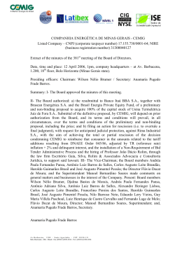
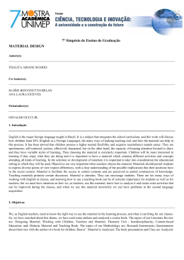
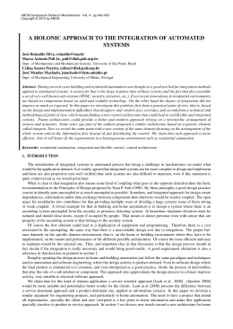
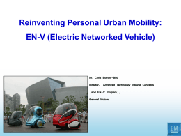
ABCM Symposium Series in Mechatronics - Vol. 5
Copyright © 2012 by ABCM
Section VII - Robotics
Page 1201
NEW ASPECTS IN THE PIRAJUBA AUV PROJECT
Ettore Apolonio de Barros, [email protected]
João Lucas Dozzi Dantas, [email protected]
Luciano Ondir Freire, [email protected]
Fabio Doro Zanoni, [email protected]
Lucas Machado de Oliveira, [email protected]
Rodrigo Telles da Silva Val, [email protected]
Polytechnic School of University of São Paulo, Department of Mechatronics Engineering, Av. Prof. Mello Moraes, 2231, cid.
Universitária, 05508-970, São Paulo – SP, Brazil.
Abstract. This work describes the progress in the development of the vehicle Pirajuba, an autonomous underwater
vehicle (AUV) that is being developed at the mechatronics department of the Polytechnic School of the University of
Sao Paulo. The paper describes its main systems, emphasizing the improvements achieved since its former version. The
embedded system is low cost and based on off the shelf components, free and largely known software tools, like C
language, and GNU compiler. The vehicle shape and manoeuvring systems are developed according to the accuracy
level required for a test bed on unmanned underwater vehicle dynamics.
Keywords: test bed, control architecture, underwater vehicles, AUV, CAN.
1. INTRODUCTION
The Pirajuba project deals with the development of a low cost AUV for investigations on dynamics and navigation
of this class of vehicle.
The vehicle geometry (Fig. 1) was inspired by the Maya AUV, which was developed under a joint IndianPortuguese project that also included the cooperation with the Unmanned Vehicles Laboratory at the University of São
Paulo for manoeuvrability studies (de Barros et al., 2004, 2006). Main differences to the original Maya version include
the hydroplanes configuration (in Pirajuba, it is adopted the cruciform type located at the rear end of the middle body),
the free flooding construction, the customized thruster, and all the embedded hardware and software systems.
Figure 1. The former version of the Pirajuba AUV during tests in a swimming pool
The original application of this AUV is the experimental support to studies on predictions of hydrodynamic
derivatives. This investigation started with the application of analytical and semi-empirical, ASE, methods to predict
derivatives of the Maya AUV (de Barros et al. 2004, 2006 and 2008a). In a latter phase, the ASE methodology has been
integrated to CFD tools in order to improve the derivative predictions (de Barros et al. 2008b). Up to now, towing tank
tests have been used for the validation of the static derivatives prediction. The use of free model tests with Pirajuba is
aimed to include the validation of the dynamic derivatives prediction as well, and to reduce the costs of the experiments.
The common type of shape related to the Myring geometry (Myring, 1974), which is present in vehicles such as
Remus and Maya, makes Pirajuba a useful test bed for studies on AUV hydrodynamics and control. In this sense,
similarly to the case of joint investigations on ship manoeuvring, this shape can be adopted as a reference for tests in
different institutions.
The AUV has been used also as a platform for academic investigations and capability improvements in the field of
underwater technology (pressure vessels, propulsion, sensing and communication), and embedded systems. Finally, the
ABCM Symposium Series in Mechatronics - Vol. 5
Copyright © 2012 by ABCM
Section VII - Robotics
Page 1202
vehicle can be viewed as a development stage of an AUV for field missions related to oceanographic and geophysical
investigations. In such case, specific acoustic and chemical sensors should be integrated to the embedded hardware and
software systems presented in this work. The eventual change in the hull and pressure vessels should be considered as
well.
This work presents the overall characteristics of the AUV. Improvements in the implementation of the hull, and
pressure vessels when compared to the former version of the vehicle (de Barros et al. 2010), are emphasized.
This paper is organized as follows. Section 2 gives an overview of the AUV geometry and its components. The
section 3 presents briefly the AUV control architecture. Section 4 describes the latest improvements in the vehicle.
Finally, section 5 provides a critical review of the progress achieved so far and proposes future developments for the
AUV project.
2. THE VEHICLE MAIN FEATURES
Pirajuba is a cruising type AUV designed for having an autonomy of 4 hours at 2m/s . The main particulars of the
vehicle are given in Tab. 1.
Table 1. Main parameters of the hull
Bare Hull Length (m)
Hull Maximum Diameter (m)
Base Diameter (m)
Nose Length (m)
Middle Body Length (m)
Myring Body Parameter θ (º)
Myring Body Parameter n
1.742
0.234
0.057
0.217
1.246
25
2
The vehicle has a Myring-type body defined by a nose section, a middle body cylindrical section, and a tail section.
The nose shape and the tail shape are described by the modified semi-elliptical radius distribution (Myring, 1974) :
r ( x)
1
d 1
2
x nl
nl
2 1/ n
(1)
and the cubic relationship
r ( x)
1
d
2
3d
2(l nl cl )2
tan
(l nl cl )
x nl cl
2
d
(l nl cl )3
tan
(l nl cl )2
x nl cl
3
(2)
respectively, where:
x is the axial distance to the nose tip,
d is the maximum hull diameter,
l is the total body length,
nl is the nose length,
cl is the middle body length,
θ, the Myring parameter, is the tail semi-angle.
The hydroplanes are formed by all movable control surfaces with the same section NACA 0012 and dimensions.
Details are given in Tab. 2.
Table 2. Main parameters of the hydroplanes
Features
Dimensions (m)
Span
0.554
Height
0.016
Root Chord
0.090
Tip Chord
0.060
Position(1)
1.373
(1)
: Distance from the leading edge to the hull nose tip
ABCM Symposium Series in Mechatronics - Vol. 5
Copyright © 2012 by ABCM
Section VII - Robotics
Page 1203
2.1. Details of the control surfaces
In the Fig. 2, it is presented a drawing of the vehicle and the hydroplanes layout.
Figure 2. Representation of the AUV particulars (dimensions are in mm)
The vehicle is a free flooding type AUV, having an external hull made of fiber glass, and three aluminum made
pressure vessels inside: the main vessel, the manoeuvring vessel and the thruster (Fig. 3). The main vessel carries the
computer units, motion sensors (rate-gyro, compass and inclinometers), depth and liquid level sensors, lithium polymer
batteries, communication and power electronics. The manoeuvring vessel includes the servo systems for moving the
control surfaces and the thruster electronic driver. The thruster vessel carries a 150W DC motor, which moves a
polyurethane propeller made by a rapid prototyping manufacturing system. The propeller parameters were selected from
the Wageningen series, and its geometry defined in a CAD based numerical tool. All the vessels structure was
calculated for operating at a depth of 100m.
Figure 3. The Pirajuba AUV components. Inside the vehicle, it is shown the manoeuvre and the main vessels. On the
left side, the inner platform of the main vessel, and the Doppler Velocity Log (DVL) sensor
3. CONTROL ARCHITECTURE DEVELOPMENT
In the Pirajuba project, one should seek for generality and extensibility in the hardware architecture. It is highly
desirable, in an AUV component project, the choice for small and simple parts that can be explored and reused in new
projects. This is a way to increase the reliability of the AUV, while keeping its project and implementation accessible to
the students.
Concerning the hardware components, it is important to orient design and implementation to the use of cheap and
locally available parts. The reason, in this case, is related to the higher risk of components damage during the work of
students, and the avoidance of schedule delays reducing the loss of short term man power. Moreover, concerning the
choice of CPUs and microprocessors, it is important to keep the choice close to the platforms familiar to the students,
reducing training and development time.
Those considerations oriented the choice of microcontroller based boards for the implementation of control units in
the embedded system. Particularly, it was selected, for most of the functions to be implemented, the ARM7 family of
ABCM Symposium Series in Mechatronics - Vol. 5
Copyright © 2012 by ABCM
Section VII - Robotics
Page 1204
microcontrollers. The navigation was implemented in the ARM9 microcontroller, since this function requires a more
powerful CPU related to the implementation of the Extended Kalman Filter (EKF) algorithm for sensor fusion.
Usually, the Ethernet has been preferred as a communication protocol, though CAN and RS-232 can be found in
some AUV implementations. However, a number of authors report drawbacks when using the Ethernet, that are related
to the space necessary for hub, and cabling, especially when redundancy should be included in the system. If one takes
into account aspects such as cost, availability, volume, cabling, energy consumption, predictability and bandwidth,
frequently CAN becomes a better choice than Ethernet.
The hardware architecture adopted in this project followed the general idea of Ortiz (1999), which proposes one
CAN bus with many sense and act nodes and one central processing unit. Cabling is reduced, less volume is occupied,
and the overall reliability is improved, since a reduced number of connectors are used. However, in this project the use
of some powerful CPUs allow for filtering and the processing functions that make their role as more sophisticated than
just sense and act nodes. The choice for more powerful processing units avoids the necessity of concentrating the
memory and intensive computing demanding tasks into PC-based systems. That enlarges the autonomy and reduces
internal heating, improving the reliability of all electronics inside the vehicle.
Taking into account a low cost architecture with availability of components in the local market, it was conceived a
CAN network, based on a number of sense/act nodes, that are employed in the automotive industry, together with one
or more main nodes using more powerful CPUs (Fig. 4). The existence of a standard electrical interface and use of
common components across the vehicle allow adding, removing, and replacing modules easily. For these operations, the
mechanical robustness of the components was taken into account, keeping the safety of assembly and handling tasks.
Figure 4. Block diagram representing part of the hardware architecture. The main electronics include systems like
Attitude Heading Reference System (AHRS), the Ultra Short Baseline system (USBL), a rate gyro, etc
Figure 5. A processing unit
Generically, each node with the ARM7 microprocessor can be represented in a three layer composition: driver, data
conversion and network control (Fig. 5 and Fig. 6). At the driver level, electrical signals from sensors or power drivers
ABCM Symposium Series in Mechatronics - Vol. 5
Copyright © 2012 by ABCM
Section VII - Robotics
Page 1205
are translated to a low current signal at a voltage level between 0 and 3.3V. Those signals are used by the peripherals
A/D and D/A converters included in the microcontroller boards.
Figure 6. Three layers compounding each node
The ARM7 based nodes, transform the network data to the binary code inserted in the D/A converters, or the data
acquired by the A/D converters to the data to be transmitted in the CAN network or through a serial port to the ARM9
processor. At this level, simple routines of data conditioning and interlocking can be included as well.
From the software development point of view, it was decided a selection of tools based on C language easily
understood by undergraduate engineering students. In this way, it is reduced the project dependence on software
engineering professionals for the code upgrade and maintenance. However, every development follows the structured
programming and object oriented concepts. Based on the same philosophy, the operational system adopted, unlike the
mainstream, is the µC-OSII, like (Lichuan, 2008), which is a commercial OS FAA certified and freely available to
universities. This OS is very simple to use and it is portable to many microprocessors. It is a very helpful resource for
embedded systems learning.
The general structure of the software architecture is composed by layers (Fig. 7).
Figure 7. Software Architecture
ABCM Symposium Series in Mechatronics - Vol. 5
Copyright © 2012 by ABCM
Section VII - Robotics
Page 1206
At the lowest abstraction level, there is the peripheral controller. It is responsible for controlling the microprocessor
peripherals through configuration registers. It is where generic routines of resource use and configuration are located,
such as PWM generation, digital/analogical conversion, serial port configuration, etc.
The second layer includes the embedded operational system, i.e. the µC-OSII, where task scheduling resources are
provided.
The third layer is responsible for driving the AUV sensors and actuators, and the communication among nodes. It is
where sensors are automatically initialized and configured as soon as the system is turned on. In this layer sensory
signal processing and interpretation is carried out, and reference values to the actuators are converted to binary codes to
feed their drivers. This layer also allows the access of each running process to the system information. That is
implemented through a shared memory, and a CAN data exchange module, where the nodes access the necessary
information for their tasks.
In the fourth layer, there are the high level functions like navigation (“EKF”), guidance, control, mission
management, etc.
4. IMPROVEMENTS IN THE VEHICLE
Improvements achieved in the third version of the vehicle refer to mechanical design of the main components of the
AUV: hull, propulsion vessel, manoeuvre vessel, and the internal structure of the main vessel.
The AUV shape should be as close as possible to the ideal geometry of the models used in the application of CFD,
and ASE methods. This is important to establish the vehicle as a reliable test bed for validating the predictions produced
by those methods. The new hull is lighter than the late version, and it was laminated on a mold which was manufactured
by numerical control of a robot manipulator from the ship model laboratory of the Institute for Technical Research
(IPT-SP). Attached to the inner part of the middle hull, there is a layer of flotation foam commonly employed for boat
construction in the marine industry. The layer allows for a lighter structure, weight balance stability, and the hull
structural reinforcement (Fig. 8). The foam also filled the inner part of the bow and stern shapes. In the latter part, the
foam structure is used for supporting the propulsion vessel (Fig. 9).
Figure 8. Hull middle body and buoyancy foam (in black).
ABCM Symposium Series in Mechatronics - Vol. 5
Copyright © 2012 by ABCM
Section VII - Robotics
Page 1207
Figure 9. Stern (left side), and bow (right side) filled with the buoyancy foams.
The new platform for the arrangement of components in the main vessel was made in aluminum, by precise electro
erosion procedures. The longitudinal beams are covered by a Teflon layer, which is also attached to the bottom of the
transversal frames for allowing the easy movement of the structure when it is placed inside the vessel. Each longitudinal
beam also includes a channel for allocating all the cabling system (Fig. 10).
The manoeuvre vessel was completely changed in order to improve the positioning accuracy of the hydroplanes, so
that the quality of the free model test for identification of the AUV dynamic model is assured. High accuracy servomotors were combined to synchronous belt transmission systems. The connection of the hydroplanes to the vessel was
also improved so that it became very simple the assembly process just before the beginning of experiments (Fig. 11).
The propulsion vessel was improved by a new combination of sealing, bearings and lubrication (Fig. 12), for
reducing the propeller shaft friction.
Figure 10. Inner platform of the main vessel
ABCM Symposium Series in Mechatronics - Vol. 5
Copyright © 2012 by ABCM
Section VII - Robotics
Page 1208
Figure 11. Manoeuvre vessel
Figure12. The new thruster
5. CONCLUSIONS
The Pirajuba project should proceed with free model tests where the system identification techniques are going to
be applied to the estimation of hydrodynamic parameters and transfer functions that represent the AUV dynamics. It is
also scheduled the vehicle application to validation and improvement of sensor fusion techniques to AUV navigation.
6. ACKNOWLEDGEMENTS
Authors would like to acknowledge the Fapesp for the financial support of these research (Proc. no 2009/10205-3),
and the scholarship support of the third author (Proc. no 2010/08628-0). Fabio D. Zanoni is sponsored by CNPq master
students scholarship.
7. REFERENCES
de Barros, E.A., Pascoal, A.M. and de Sá, E., 2004. “AUV dynamics: modeling and parameter estimation using
analytical, semi-empirical, and CFD methods”. Proceedings of CAM’s 2004.
de Barros, E.A., Pascoal, A.M. and de Sá, E., 2006. “Progress towards a method for predicting AUV maneuvers”.
Proceedings of MCMC2006 - 7th IFAC Conference on Manoeuvring and Control of Marine Craft, pp. 1–8.
de Barros, E.A., Pascoal, A.M. and de Sa, E., 2008a. “Investigation of a method for predicting AUV derivatives”.
Ocean Engineering, Vol. 35, No. 16, pp. 1627 – 1636. ISSN 0029-8018. doi: 10.1016/j.oceaneng.2008.08.008.
ABCM Symposium Series in Mechatronics - Vol. 5
Copyright © 2012 by ABCM
Section VII - Robotics
Page 1209
de Barros, E., Dantas, J., Pascoal, A. and de Sa, E., 2008b. “Investigation of normal force and moment coefficients for
an AUV at nonlinear angle of attack and sideslip range”. Oceanic Engineering, IEEE Journal of, Vol. 33, No. 4, pp.
538–549. ISSN 0364-9059. doi:10.1109/JOE.2008.2004761.
de Barros, E.A., Freire, L.O. and Dantas, J.L.D., 2010. “Development of the pirajuba AUV”. In Proceedings of
CAMS2010 - Control Applications in Marine Systems.
Oliver, G., Avia, D., de Diego, M., Ortiz, A. and Proenza, J., 2000. "RAO: a low cost AUV for testing". In Proceedings
of OCEANS 2000 MTS/IEEE Conference and Exhibition, v. 1, p 397-401.
Ortiz, A., Proenza, J., Bernat, G. and Oliver, G., 1999. "Improving the safety of AUVs". In Proceedings of OCEANS’99
MTS/IEEE, v. 2, p. 979-984.
Lichuan, Z., Demin, X., Jun, L., and Lijun, J., 2008 "Design and experiment of automatic pilot for long range AUVs".
3rd IEEE Conference on Industrial Electronics and Applications, ICIEA 2008, p 1824-1827.
5. RESPONSIBILITY NOTICE
The authors are the only responsible for the printed material included in this paper.
Baixar