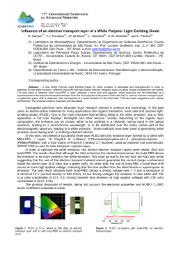
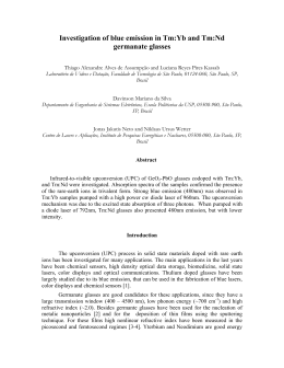
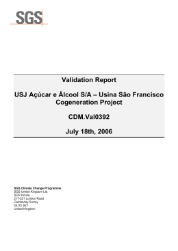
PROJECT DESIGN DOCUMENT FORM (CDM PDD) - Version 03 CDM – Executive Board page 1 CLEAN DEVELOPMENT MECHANISM PROJECT DESIGN DOCUMENT FORM (CDM-PDD) Version 03 - in effect as of: 28 July 2006 CONTENTS A. General description of project activity B. Application of a baseline and monitoring methodology C. Duration of the project activity / crediting period D. Environmental impacts E. Stakeholders’ comments Annexes Annex 1: Contact information on participants in the project activity Annex 2: Information regarding public funding Annex 3: Baseline information Annex 4: Monitoring plan PROJECT DESIGN DOCUMENT FORM (CDM PDD) - Version 03 CDM – Executive Board page 2 SECTION A. General description of project activity A.1. Title of the project activity: Title: La Merced de Jondachi Hydroelectric Project Version: 1.0 Date Completed: 10/02/2012 A.2. Description of the project activity: La Merced de Jondachi Hydroelectric Project (LMJHP) considers the construction and operation of a run-of-river hydroelectric plant, with a nominal capacity of 18.10 MW, which will be located on the Cotundo Parish, Archidona Canton, Napo Province, Republic of Ecuador. The project activity will be developed by the Electric Corporation of Ecuador (Corporación Eléctrica del Ecuador - CELEC EP)1. The LMJHP considers the production of clean energy using the Jondachi’s River water flow, which is an affluent of the Hollin River. The project activity will collect the water from the river’s right margin, and through an open canal the water will be conducted into a sand screen. Afterwards, the water will be conducted through a covered canal to a free water flow tunnel, continuing to another section of a closed canal, which will deliver the water into the charge tank from the start of the pressure pipe to the power house, guiding the water flow towards the turbines. The power house will be equipped with two Francis turbines and their respective generators, valves and control panel. The elevating substation will be located by the power house. A transmission line will be installed to the switching substation, and will be connected to the Tena-Coca Transmission Line (138 kV) which is part of the Interconnected National System of Ecuador (Sistema Nacional Interconectado – SNI)2. The project activity will begin its operation in 2014, and will replace part of the energy generated by power plants connected to the SNI that burn fossil fuels; this replacement will result in a reduction of greenhouse gas (GHG) emissions. The estimated annual energy generation of the project activity is 112.73 GWh that will be delivered to the SNI; resulting in an approximate reduction of 60,288 tCO2e/yr, and totaling, for the first crediting period, an approximate reduction of 422,016 tCO2e. In the current scenario (before project activity implementation) there are no generation plants operating at the project site. In an event in which the project activity would not be implemented, the baseline scenario corresponds to the energy supply from the generation plants connected to the SNI (continuation of the current situation). The project activity contributes to the sustainable development on the following aspects: 1 LMJHP initially was studied by Termopichincha S.A., which is a company founded after the fragmentation of the Ecuadorian Electrification Institute (INECEL - Instituto Ecuatoriano de Electrificación). On January 13, 2009, the private entities Electroguayas, Hidroagoyan, Hidropaute, Termoesmeraldas, Termopichincha, and Transelectric, decided to merge in order to constitute CELEC S.A.; Termopichicha was left as a Business Unit in charge of the operation of the project activity. Later, on January 14 2010, though executive Decree No. 220, the public entity CELEC EP was created, and CELEC S.A. and Hidronacion S.A. transferred their obligations and responsibilities. 2 Reference: Technical Document “Informe Principal a nivel de licitación – Proyecto Hidroeléctrico La Merced de Jondachi”, November 2011. PROJECT DESIGN DOCUMENT FORM (CDM PDD) - Version 03 CDM – Executive Board page 3 A.3. replacement of fossil fuels for energy generation, resulting in the reduction of GHG and other pollutants that affect people’s health; increase of electricity generation from renewable sources; increase of the reliability of the Ecuadorian Power System; reduction of energy imports; positive social impacts due to new employment during the construction, operation, and maintenance of the project activity; adequate and sustainable use of hydrological resources; additional public revenue which will generate local and national benefits. Project participants: Name of Party involved (*) (host) indicates a host Party) Private and/or public entity(ies) project participants (*) (as applicable) Kindly indicate if the Party involved wishes to be considered as project participant (Yes/No) Republic of Ecuador (host country) CELEC EP (Public Entity) No (*) In accordance with the CDM modalities and procedures, at the time of making the CDM-PDD public at the stage of validation, a Party involved may or may not have provided its approval. At the time of requesting registration, the approval by the Party (ies) involved is required. Note: When the PDD is filled in support of a proposed new methodology at least the host Party (ies) and any known project participant (e.g. those proposing a new methodology) shall be identified. A.4. Technical description of the project activity: A.4.1. Location of the project activity: A.4.1.1. Host Party(ies): Republic of Ecuador A.4.1.2. Region/State/Province etc.: Province of Napo A.4.1.3. City/Town/Community etc.: Canton of Archidona – Cotundo Parish A.4.1.4. Details of physical location, including information allowing the unique identification of this project activity (maximum one page): The LMJHP is located in the center of the Napo Province, Archidona Canton, Cotundo Parish. The project activity will use the waters of the Jondachi River, affluent of the Hollin River, and will collect the PROJECT DESIGN DOCUMENT FORM (CDM PDD) - Version 03 CDM – Executive Board page 4 waters at the level of 1,153.70 masl. The water intake will be located 80 m downstream from the confluence of the Jondachi and Urcusiqui Rivers, 1 km southwest of the La Merced de Jondachi, which is 28 km from the city of Tena. The access to the project activity will be by the Quito-Baeza-Tena highway. The project activity will be located 165 km from Ecuador’s Capital, Quito. Physical location of the project’s activity most important components are3: Ítem Intake Sand screener Charge tank Pressure pipe Power house Discharge Coordinates (WGS18) Zone 18 North East 9,921,314.70 187,366.14 9,921,262.25 187,444.73 9,917,998.96 189,426.93 9,917,962.99 189,440.73 9,917,920.74 189,833.15 9,917,920.75 189,833.15 Level (masl) 1,153.66 1,153.26 1,147.52 1,141.45 992.5 992.5 Table: Coordinates UTM of the Project (WGS 84 – Zone 18) and level of the Components The location of the project activity is shown on the figure below: Source: Bidding Principal Report, La Merced de Jondachi Hydroelectric Project, November 2011. Figure: The project activity location 3 Reference: Environmental Impact Report – La Merced de Jondachi Hydroelectric Project, 2011 PROJECT DESIGN DOCUMENT FORM (CDM PDD) - Version 03 CDM – Executive Board page 5 A.4.2. Category(ies) of project activity: According to the Kyoto Protocol Annex A, the project falls under sectoral scope 1: Energy industries « renewable - / non-renewable sources». A.4.3. Technology to be employed by the project activity: LMJHP consists of the construction and operation of a run-of-river hydroelectric plant of 18.10 MW, with an annual generation average of 112.73 GWh. The expected lifetime of the hydroelectric plant is 50 years. The project activity will be developed on the Jondachi River’s right margin and will include: the intake, which is located 80 m downstream from the confluence of the Urcusiqui and Jondachi Rivers; the sand screener, which will be located 292 m from the intake; the river’s gravity conduct on the right margin, which finishes at the charge tank; the pressure pipe of 414.67 m of length and 2 m of diameter; the powerhouse where two horizontal turbines (Francis type) with a nominal capacity of 9.05MW each will be located; and, a restitution canal for the turbinated water returning to the Jondachi River, which would be 4.3 km downstream from the intake. A substation, which will be located by the power house, will transform the voltage tension from 13.8 kV to 138 kV. The 420 meter long transmission line will transport the energy to the switching substation, which will be connected to the Tena-Coca 138 kV transmission line belonging to the SNI. The following graph shows the principal components of the project activity: PROJECT DESIGN DOCUMENT FORM (CDM PDD) - Version 03 CDM – Executive Board page 6 Source: Definitive Environmental Impact Assessment, La Merced de Jondachi Hydroelectric Project, September 2011. Figure: General description of the project activity The summary of the main technical characteristics for the project activity is presented in the following table4: 4 The details of the project activity are taken from the technical document “Informe Principal a nivel de licitación – Proyecto Hidroeléctrico La Merced de Jondachi”, November 2011. PROJECT DESIGN DOCUMENT FORM (CDM PDD) - Version 03 CDM – Executive Board page 7 Intake 3 Nominal flow Ecological flow Structure 13.35 m /s 2.2 m3/s Mobile dam with a fixed wire Height of the dam Length of the dam 2.50 m Fixed 23.8 m (2 stretches) and mobile: 20 m (4 stretches) 1,153.2 masl (80 m downstream from the confluence of the Urcusiqui and Jondachi Rivers) Sand screener (hydraulic design) 292 m from the intake 130.07 m Double chamber Length: 75 m, width: 7.80 m Level Location Length Structure Dimensions Conducts Slope Length Dimensions Level Level Length Selected width for the tank Charge tank volume Dimension Type of screen Separation between screen and incoming pressure pipe Material Diameter Length Static height Thickness Type Dimensions Type Units Dimensions 0.12% 379.10 (open canal) + 3,084.83 m (tunnel)+ 719.85 m (covered canal) = 4,183.78 m 2.5 m x 3.0 m (open canal) + 2.5 m x 3.2 m (tunnel)+ 2.5 m x 3.0 m (open canal) Intake exit: 1,152.81 masl, Incoming discharge tank: 1,146.92 masl Charge tank or pressure tank Mid water level 1,146.92 masl 50 m 10 m 1,561.23 m3 48.10 m x 10.0 m Thin screen 40 mm (adequate for the type of turbine used in the project) Pressure pipe Steel (ASTM 516 grade 70) 2,000 mm 82.53 m (Section 1) + 185.98 m (Section 2) + 91.47 m (Section 3) + 54.69 m (Section 4) = 414.67 m 35.3 m (Section 1), 87.76 m (Section 2) , 132.26 m (Section 3), 159.55 m (Section 4) 8 mm (Section 1), 10 mm (Section 2), 14 mm (Section 3), 16 mm (Section 4) Powerhouse Open top 36.86 m x 17.60 m Discharge Rectangular open top Two units of 6.7 m3/s each. Length: 30.67 m, width: 3 m PROJECT DESIGN DOCUMENT FORM (CDM PDD) - Version 03 CDM – Executive Board page 8 Type Number of Turbines Nominal capacity Nominal flow per unit Turbine efficiency for nominal power Nominal net fall Net height Number of generators Nominal capacity Power (MVA) RPM Number of poles Nominal tension Nominal frequency Power factor Dimensions Equipment Voltage Number of phases Voltage Length Voltage Turbines Francis, horizontal axis 2 9.05 MW each (total capacity 18.10 MW) 6.68 m3/s 92.7 % 153.5 m Minimum: 151.82 m, maximum: 155.22 m Generators 2 9 MW 10.333 MVA 600 12 13.8 kV 60 Hz 0.90 Elevation substation 32.60 m x 33.82 m Cutting and protection equipment and measurement transformers 13.8 kV / 138 kV Transmission line 3 138 kV 420 m Switching Substation (SNI) 138 kV Table: Main characteristics of the project activity Monitoring technology of the project activity The LMJHP will have its energy delivery point at the outlet of the switching substation. A commercial type net energy metering system will be installed at this point composed of a 0.2 precision class redundant meter, with real time communication to CENACE using standardized protocols. In conformity with the Electrical Sector Regimen Law, the wholesaler Electrical Market is controlled by the CENACE and all the hardware that will be implemented for the Supervision System, Control, and Acquisition of Data (SCADA), as well as the elements and metering system, control, and protection, will have to comply with the relevant specifications, including those established in the CONELEC Regulation 005/08 “Requirements for the supervision and real time control of the SNI by CENACE” 5. Two net energy meters will be installed at the outlet of the switching substation (meter 1 will be connected to the Coca transmission line and meter 2 will be connected to the Tena Transmission Line). Each meter will have an auxiliary meter. The basic data for the energy meters is shown on the table below: 5 Reference: http://www.conelec.gob.ec/normativa_detalle.php?cd_norm=256 PROJECT DESIGN DOCUMENT FORM (CDM PDD) - Version 03 CDM – Executive Board page 9 Item Feeding nominal tension Metering nominal tension Metering nominal current Permanent current Operation Frequency Synchronization Technology 115 V c.c. (+10%,-15%) 13.8 kV 500 A 5A 60 Hz GPS grid communication Table: Main characteristics of the monitoring equipment A.4.4. Estimated amount of emission reductions over the chosen crediting period: The project participant has selected a crediting period of 7 years (renewable twice). The following table summarizes the emission reductions for the first crediting period. Years 2014 (*) 2015 2016 2017 2018 2019 2020 2021 (**) Annual estimation of emission reductions in tonnes of CO2e 30,144 60,288 60,288 60,288 60,288 60,288 60,288 30,144 Total Estimated Reductions (tonnes of CO2e) Total number of crediting years Annual average over the crediting period of estimated reductions (tonnes of CO2e) 422,016 7 60,288 (*) (**) 6 months of operation Table: Estimation of annual emission reductions A.4.5. Public funding of the project activity: The development of the project activity does not involve public funding from an Annex I country. PROJECT DESIGN DOCUMENT FORM (CDM PDD) - Version 03 CDM – Executive Board page 10 SECTION B. Application of a baseline and monitoring methodology B.1. Title and reference of the approved baseline and monitoring methodology applied to the project activity: The methodology used for this project activity is ACM0002 “Consolidated baseline methodology for grid-connected electricity generation from renewable sources, v.12.3.0” (EB66). As required by the methodology ACM0002, the following tools have also been used: “Tool to calculate the emission factor for an electricity system v.02.2.1”. “Tool for the demonstration and assessment of additionality v.06.0.0”. B.2. Justification of the choice of the methodology and why it is applicable to the project activity: ACM0002 v.12.3.0 is applicable to grid-connected renewable power generation project activities that: a) consider the installation of a new power plant at site where no renewable power plant was operated prior to the implementation of the project activity (Greenfield plant); b) involve the capacity addition; c) involve a retrofit of (an) existing plant (s); or, d) involve a replacement of (an) existing plant (s). As the project activity corresponds to the installation of a new power plant at a site where no renewable power plant was operated, it fulfills condition a), therefore ACM0002 v.12.3.0 was considered the methodology most appropriate to be used. The methodology is applicable under the following conditions: Applicability conditions Fulfillment of conditions The project activity is the installation, capacity addition, retrofit or replacement of a power plant/unit of one of the following types: hydro power plant/unit (either with a run-of-river reservoir or an accumulation reservoir), wind power plant/unit, geothermal power plant/unit, solar power plant/unit, wave power plant/unit or tidal power plant/unit; In the case of capacity additions, retrofits or replacements (except for capacity addition projects for which the electricity generation of the existing power plant(s) or unit(s) is not affected): the existing plant started its commercial operation prior to the start of a minimum historical reference period of five years, used for the calculation of baseline emissions and defined in the baseline emission section, and no capacity addition or retrofit of the plant has been undertaken between the start of this minimum historical reference period and the implementation of the project activity; The project activity considers the installation of a new run-of-river hydro power plant of 18.10 MW nominal capacity connected to the SNI. This condition does not apply to the project activity since it does not consider the capacity addition, retrofit or replacement of an existing power plant. PROJECT DESIGN DOCUMENT FORM (CDM PDD) - Version 03 CDM – Executive Board page 11 In case of hydro power plants, at least one of the following conditions must apply: the project activity is implemented in an existing single or multiple reservoirs, with no change in the volume of any of the reservoirs; or the project activity is implemented in an existing single or multiple reservoirs, where the volume of any of the reservoirs is increased and the power density of each reservoir is greater than 4 W/m2 after the implementation of the project activity; or the project activity results in new single or multiple reservoirs and the power density of each reservoir is greater than 4 W/m2 after the implementation of the project activity. The methodology is not applicable to project activities that involve switching from fossil fuels to renewable energy sources at the site of the project activity, since in this case the baseline may be the continued use of fossil fuels at the site. The methodology is not applicable to biomass fired power plants. The methodology is not applicable to hydro power plants that results in the creation of a new single reservoir or in the increase in an existing single reservoir where the power density of the reservoir is less than 4 W/m2. The project activity does not result in a new reservoir or an increase of an existing reservoir. The project activity does not involve switching from fossil fuels to renewable energy sources. The project activity does not include the installation of a biomass power plant. The project activity does not result in a new reservoir or an increase of an existing reservoir. Table: Fulfilment of applicability conditions B.3. Description of the sources and gases included in the project boundary: According to the ACM0002 v.12.3.0, the project boundary must be evaluated in terms of the emission sources and their spatial extent. The project boundary includes the LMJHP and all power plants physically connected to the SNI. The following activities and emission sources are considered within the project boundary: PROJECT DESIGN DOCUMENT FORM (CDM PDD) - Version 03 CDM – Executive Board page 12 Project activity Baseline Source Gas CO2 emissions from electricity generation in fossil fuel fired power plants that are displaced due to the project activity For hydro power plants, emissions of CH4 from the reservoir Included? CO2 Yes CH4 N2O No No CO2 No CH4 No N2O No Justification / explanation Main emission source. In the baseline, CO2 emissions are generated due to the operation of fossil fuel fired power plants connected to de grid. Minor emission source. Minor emission source. Minor emission source. The project activity does not require a reservoir. Minor emission source. Table: Definition of the project boundary B.4. Description of how the baseline scenario is identified and description of the identified baseline scenario: According to ACM0002 v.12.3.0, if the project activity is the installation of a new grid-connected renewable power plant/unit, the baseline scenario is as follows: “Electricity delivered to the grid by the project would have otherwise been generated by the operation of grid-connected power plants and by the addition of new generation sources, as reflected in the combined margin (CM) calculations as described in the Tool to calculate the emission factor for an electricity system”. The baseline scenario identified corresponds to the continuation of the current situation in which the electricity is delivered to the SNI. Energy that would have been generated by LMJHP will be supplied by the operation of power plants connected to the grid, the addition of new generation capacity and energy imports. B.5. Description of how the anthropogenic emissions of GHG by sources are reduced below those that would have occurred in the absence of the registered CDM project activity (assessment and demonstration of additionality): CDM consideration After considering the benefits of the CDM in the decision of proceeding with the project activity, the promoter has developed permanent and real actions in order to assure the CDM status in parallel to the implementation of the project activity. The following table details the project timeline. PROJECT DESIGN DOCUMENT FORM (CDM PDD) - Version 03 CDM – Executive Board page 13 Date Nov 2008 Nov 2008 Nov 2008 Ago 2009 Apr 2011 Sep 2011 Oct 2011 Jul 2012 Jul 2012 Jul 2014 Milestone The Project Idea Note (PIN) was submitted to the Designated National Authority (DNA) of Ecuador. The DNA was notified by the project promoter about the CDM prior consideration 6. The project promoter notified the UNFCCC secretariat about the project activity and its intention to seek the CDM status7. Contract signed between CELEC S.A., TERMOPICHINCHA and ASTEC for the “Feasibility study and design for the construction of La Merced de Jondachi hydro power plant”. The CDM has been considered in the economic/financial evaluation evidencing that the project activity requires the income from CDM in order to be viable. The Electricity and Renewable Energies Ministry (MEER) and the Inter-American Development Bank (IDB) agreed on a technical assistance to develop the CDM project activity. UNFCCC publishes the notification of prior CDM consideration. CONELEC approves the Definitive Environmental Impact Assessment (DEIA). Expected starting date for the project activity (the project participant and technical developer will sign the EPC contract). Expected date for the beginning of the project construction. Expected date for the beginning of the project operation. Table: Timeline for the project activity Additionality analysis In order to demonstrate that the proposed project activity does not correspond to the baseline scenario, the additionality analysis has been developed as established by the “Tool for the demonstration and assessment of additionality v.06.0.0”, according to the ACM0002 v.12.3.0. The tool allows evaluating and demonstrating the additionality through the application of the following steps: Step 1. Identification of alternatives to the project activity consistent with current laws and regulation Sub-step 1a. Definition of alternatives to the project activity: According to paragraph 105 of the Validation and Verification Manual, given that the applied methodology establishes the baseline scenario conditions, different alternative analysis is not necessary. Considering the identified baseline, the realistic and credible alternative baseline scenarios for LMJHP correspond to: a. The project activity not implemented as a CDM project activity. b. Continuation of the current situation of the electricity supply. This means to continue the electricity supply through the power plants connected to the SNI (electricity delivered to the grid by the project activity is generated by existing power plants connected to the grid, additions of new generation sources and energy imports) 6 7 Reference: OFICIO No. PE-GPRY-528-2008 (early notification AND.pdf). Reference: OFICIO No. PR-GPRY-528-2008 (early notification UNFCCC.pdf). PROJECT DESIGN DOCUMENT FORM (CDM PDD) - Version 03 CDM – Executive Board page 14 Sub-step 1b. Consistency with mandatory laws and regulations: All identified alternatives in sub-step 1a comply with the laws and regulations of Ecuador, such as the Organic Law of Public Companies (Ley Orgánica de Empresas Públicas8). Therefore, there are no legal restrictions that could prevent the implementation of the LMJHP without the income from the sale of certified emissions reductions (CER’s) (alternative a) or the continuation of the current situation (alternative b). Step 2. Investment analysis The investment analysis shall determine if the proposed project activity is, or is not, the most economically or financially attractive scenario; or if the project activity is not economically or financially feasible, without the revenue from the sale of certified emission reductions (CERs). Sub-step 2a: Determine appropriate analysis method: According to the “Tool for the demonstration and assessment of additionality v.06.0.0”, three options can be applied to conduct the investment analysis. These are: simple cost analysis (option I); investment comparison analysis (option II); and, benchmark analysis (option III). In order to demonstrate that the proposed project activity is not economically or financially feasible without the revenue from the sale of CERs option III – “Apply benchmark analysis” is applied. Sub-step 2b. Option III. Apply benchmark analysis The indicator that will be used is the return on the equity (equity IRR) with a benchmark of 17% according to the “Guidance on the assessment of investment analysis, v.5”. Sub-step 2c. Calculation and comparison of financial indicators The table below presents the main parameters used in the calculation of the expected return on the equity. 8 Reference: http://docs.ecuador.justia.com/nacionales/leyes/ley-de-empresas-publicas.pdf PROJECT DESIGN DOCUMENT FORM (CDM PDD) - Version 03 CDM – Executive Board page 15 Main parameters Total initial investment Financial mix Debt Financial rate Credit period Average annual electricity generation Electricity Price Unit Value US$ 39,178,532 Equity % US$ Annual % years 20% 31,342,826 6.5% 20 GWh/year 112.73 US$/MWh Source 46.53 Feasibility study and bid (tender) design study of the project activity completed by ASTEC CIA LTDA Company. “Cost analysis for power generation companies subject to price regulation. January – December 2011” prepared by CONELEC’s tariffs department. Res.No.013/11 marzo 17, 2011 Expenses (excl. depreciation) US$/year 1,944,713 Lifetime of the years project activity Data for the CDM evaluation Price of CERs (Dec. 2014) 52 5.89 €/tCO2e, www.barchart.com/quotes/futures/CQZ14 8.42 US$/tCO2e Equity IRR (without CERs) IRR Benchmark Feasibility study and bid (tender) design study of the project activity completed by ASTEC CIA LTDA. 50 years of operation and 2 years of construction Exchange rate 1,43 US$/€ Ecuadorian Central Bank 8.93% 17% Table. Main parameters used for the calculation of the Equity IRR Benchmark: The benchmark used is the value provided in the appendix to the “Guideline on the assessment of investment analysis, version 05”. The benchmark for Ecuadorian projects belonging to group 1 (in which LMJHP is included) is 17%. The value established for the benchmark reflects Ecuador’s high credit risk9. Comparison of Equity IRR to the benchmark: The equity IRR is compared to the benchmark to examine the financial viability of the project activity. The IRR of 8.93% (without CERs) is lower than the benchmark of 17%; this means that the project activity is not viable and demonstrates that the CDM is necessary in order for the investment to be more profitable. 9 Reference: Classification Moody’s Rating for Bonds. PROJECT DESIGN DOCUMENT FORM (CDM PDD) - Version 03 CDM – Executive Board page 16 Sub-step 2d. Sensitivity analysis The purpose of the sensitivity analysis is to demonstrate that the financial analysis is strong and that the conclusions are solid, even when facing changes in the main input variables. Variables included in this analysis are all variables that constitute more than 20% of total costs or revenues, including the initial investment: Investment expenses, CAPEX. Operational expenses, OPEX. Electricity sale price. CERs sale price. If we take as a reference the average scenario (without CERs) of 8.93% for the IRR, we can observe that the largest incidence of CERs in Equity IRR is 2.84% when there is an increase of 10% in the electricity price. In all scenarios in which the variables mentioned have been applied, the IRR is lower than the benchmark. As it is shown in the table below, even when the CERs are included in the cash flow, equity IRR is not higher than the benchmark with the exception of the increase of the electricity sale price in 10%. It can be concluded that in any scenario, LMJHP is not a financially feasible project and requires the income from CERs in order to assure positive flows towards the equity. Average Scenario CAPEX + 10% CAPEX - 10% OPEX +10% OPEX -10% Electricity price +10% Electricity price - 10% Without CERs Equity IRR 8.93% 8.33% 9.55% 8.45% 9.43% 11.93% 6.32% With CERs Equity IRR 11.29% 10.58% 12.03% 10.71% 11.89% 14.77% 8.20% Table. Sensitivity result of the financial analysis As it can be observed in the table below, when the sale price of the CERs is considered in a range between the current values and the values observed on September 2011 (€ 9 - 11€/tCO2e), we can observe that the project activity becomes more financially attractive even if it not exceeds the benchmark. PROJECT DESIGN DOCUMENT FORM (CDM PDD) - Version 03 CDM – Executive Board page 17 CERs prices to be delivered on December 2014 (observed prices during July-December 2011)10 Equity return considering CERs revenues IRR € 5.89/tCO2e € 7.00/tCO2e € 8.00/tCO2e € 9.00/tCO2e € 11.00/tCO2e 11.29% 11.80% 12.27% 12.76% 13.78% According to the previous table, the variable that has a greater change is the price of the CERs. This variation can be reflected when taking the current price of €5.89 and comparing it to the previous price of €11.00 (July 2011), showing a decrease in the price of the CERs of 46.45%. Even with this variation in price, the result in the IRR calculation fluctuates between 11.29% and 13.78%. To conclude, as it has been demonstrated in this investment analysis, the effect of the contribution by the CERs is financially significant and determinant from the project’s activity financial feasibility point of view, since: 1. The CERs provide stability and certainty to the equity’s cash flow while reducing its financial risk, and increasing the equity IRR in 2.36% from 8.93% (without CERs), to 11.29% (incl. CERs). 2. It is shown that the CERs contribute to a significant and precise increase in equity value and, in a case in which CER market prices would return to levels prior to September 2011, to surpass the benchmark IRR level. Step 3. Barrier analysis The analysis presented in the previous step shows that the project activity is not attractive from a financial point of view; therefore the project developer chose not to apply this step as indicated by the tool. Step 4. Common practice analysis Sub-step 4a. Analyze other activities similar to the proposed project activity According to the “Tool for the demonstration and assessment of additionality” v.06.0.0 the analysis of other activities that are operational and that are similar to the project activity must include activities that are in the same country, have similar technology, are of a similar scale, and take place in a comparable environment with respect to regulatory framework, investment climate, access to technology and access to financing. The analysis must be determined considering other run-of-river hydroelectric projects in the country. As the LMJHP project activity has a nominal capacity of 18.10 MW, according to the guidelines on common practice, the applicable output range for comparison of run-of-river hydroelectric projects must consider those whose capacities are between 9.05 MW and 27.15 MW. The hydro power plants in Ecuador have been operating under different regulation and investment conditions. Projects implemented before 1996 had a different investment scenario. Since 1996, the 10 Reference: www.barchart.com/quotes/futures/CQZ14 PROJECT DESIGN DOCUMENT FORM (CDM PDD) - Version 03 CDM – Executive Board page 18 sector’s regulation has been modified to promote private investments in the power sector 11. Accordingly, it is acceptable to exclude from the common practice analysis projects implemented before 1996. Similarly, projects implemented before 2008 can be excluded. The Ecuadorian electricity market’s reform reduced legal benefits affecting generation companies (23th July, 2008)12 such as Termopichincha, changing tariffs, responsibilities and funding, driving the electricity market into a transition period. Accordingly, development conditions for the energy sector prior to 2008 did not face a similar context regarding regulatory frames, investment and funding access than those developed after 2008. Considering the above, the analysis of the comparable environment indicates that only run-of-river hydroelectric projects after 2008 can be considered similar to the proposed project activity. | Consequently, after a detailed revision of the hydropower plants in operation after 2008 that are connected to the SNI, no similar activities to the project activity are presented, as it is shown in the table below. Starting operation year 2007 2002 2000 N.1 G1 2.5 0.5 3.13 14.7 2.95 1998 1997 1997 1990 1987 U1, U2 160 1987 U1, U2, U3, U4 7.4 1980 Company Unit San Francisco Loreto El Carmen Hidropastaza Ecoluz EMAAP-Q U1, U2 Loreto U1 Península Ambato G1, G2, G3, G4 Río Blanco Recuperadora San Miguel de Car Riobamba EMAAP-Q Norte CELEC – Hidroagoyán Agoyán Guangopolo_Q 11 Installed capacity (MW) 230 2.15 8.4 Power plant Quito U5 2 1956 Nayón Quito U6 U1, U2 11.52 29.7 1985 1980 Saucay Elecaustro Pasochoa Quito G1, G2 G3, G4 U1, U2 U1, U2 16 16 4.5 20 1978 1982 1976 1962 Cumbayá Quito U3 10 1967 U4 G1 10 2.19 1976 1965 G2 U1 4.44 0.56 1982 1966 U2 1.1 1978 Grupo 1 y 2 5.2 1966 Papallacta Ecoluz Chimbo CNEL-Bolívar Alao Riobamba Reference: Law of the Electricity Sector (Ley de Régimen del Sector Eléctrico – LRSE), Official register N° 42, October 10th, 1996. 12 Under this new regulation, the electricity market marginal cost concept is eliminated from the generation component and investment costs or distribution or transmission expansions are not covered. Equally it was stated that the government will cover the costs of generation, distribution and transmission investment, creating an investment scenario with reduced incomes for t he companies. PROJECT DESIGN DOCUMENT FORM (CDM PDD) - Version 03 CDM – Executive Board page 19 Power plant Company Ambi Norte Illuchi No. 1 Cotopaxi Los Chillos Quito Carlos Mora Sur La Playa San Gabriel Norte Norte Saymirín Elecaustro Grupo 3 Installed capacity (MW) 2.6 Starting operation year 1977 Grupo 4 2.6 1978 G1 G2 4 4 1968 1968 Group 1 0.697 1951 Unit Group 3 1.4 1955 Group 4, 1 y 2 6.6 1987 U1 0.88 1953 U2 U1 U2 U3 G1, G2, G3 G1 G1, G2 G3, G4 G5,G6 0.88 0.6 0.6 1.2 1.32 0.23 2.52 3.92 8 1984 1956 1961 1967 1957 1957 1957 1964 1995 Table: Run-off river hydropower plants connected to the SNI in 2010 In conclusion there are no activities in Ecuador comparable with LMJHP and the implementation of run-of-river hydroelectric projects cannot be considered a prevailing practice. Sub-step 4. Discuss any similar options that are occurring In Sub-step 4a it has been demonstrated that there are no projects similar to the project activity. B.6. Emission reductions: B.6.1. Explanation of methodological choices: According to ACM0002 (v.12.3.0), the procedure to determine the emission reductions attributable to the project activity is as follows: Project emissions The project activity is a run-off river hydro power plant, thus the project emissions are zero, as it is specified in the selected methodology. Baseline emission The baseline emissions correspond to the MWh generated by the renewable energy power plant that are delivered to the grid, multiplied by its emission factor (measured in tCO 2e/MWh) as presented below: PROJECT DESIGN DOCUMENT FORM (CDM PDD) - Version 03 CDM – Executive Board page 20 BE y EG PJ,y EFgrid,CM, y Where: BEy EGPJ,y EFgrid,CM,y Baseline emissions in year y (tCO2). Quantity of net electricity generation that is produced and fed into the grid as a result of the implementation of the CDM project activity in year y (MWh). Combined margin CO2 emission factor for grid connected power generation in year y calculated using the latest version of the ”Tool to calculate the emission factor for an electricity system” (tCO2/MWh). Calculation of EGPJ,y The LMJHP consists of the installation of a new grid-connected renewable power plant/unit at a site where no renewable power plant was operated prior to the implementation of the project activity, therefore: EG PJ,y EG facility,y Where: EGPJ,y EGfacility,y Quantity of net electricity generation that is produced and fed into the grid as a result of the implementation of the CDM project activity in year y (MWh). Quantity of net electricity generation supplied by the project plant/unit to the grid in year y (MWh). For the project activity the amount of net energy that will be delivered to the SNI EGfacility,y has been estimated as shown in section B.6.3. Calculation of the EFgrid,CM,y The combined margin emission factor (emission factor of the Ecuadorian electricity system) has been calculated using the “Tool to calculate the emission factor for an electricity system v.02.2.1”, using information published by the CENACE13. According to this tool, the combined margin emission factor is determined applying the following steps: Step 1. Identify the relevant electricity power systems The electricity system of the project activity is defined by the spatial extent of the power plants that are physically connected to the grid through transmission and distribution lines belonging to the SNI. SNI is Ecuador’s National Interconnected System of electricity, and it is also connected to the Colombian and Peruvian grids. 13 The Centro Nacional de Control de Energía (CENACE) is a private organization, whose members include all the companies of generation, transmission and distribution together with the greater consumers. It contributes with the coordination of the National Interconnected System and the management of the technical and financial operations of the Wholesale Electric Market (MEM). PROJECT DESIGN DOCUMENT FORM (CDM PDD) - Version 03 CDM – Executive Board page 21 Hydro electricity Biomass Thermo electricity Imports Total 2010 (GWh) 8,470.08 115.29 7,754.04 986.19 17,325.61 % 48.9% 0.6% 44.8% 5.7% 100% Table: Electricity generation of the SNI Step 2. Choose whether to include off-grid power plants in the project electricity system (optional) Project participants may choose one of the options below for calculating the operating margin and build margin emission factors: Option I: Only power plants inside the grid are included in the calculation. Option II: Power plants in and outside the grid are both included in the calculation. Option I has been selected for the emission factor calculation. Step 3 - Select a method to determine the operating margin (OM) For the operating margin emission factor calculation, the simple adjusted method has been selected (option b of the tool) since public official information is available from the electricity generation units of Ecuador (CENACE). The approximation ex-ante has been selected, using for its calculation series of data from the last 3 years, which are available at the beginning of the validation. Step 4- Calculate the operating margin emission factor according to the selected method. The simple adjusted operating margin emission factor (EF OM,adjusted,y, expressed in tCO2/MWh) is a variation of the simple operating margin, where power plants (including imports) are separated in low cost/must run plants (k) and other sources (m). EFOM,adjusted,y will be calculated considering an ex-ante approximation. Where: EFgrid,OM-adj,y λy EGm,y EGk,y EFEL,m,y EFEL,k,y m Simple adjusted operating margin CO2 emission factor in year y (tCO2/MWh) Factor expressing the percentage of time when low-cost/must-run power units are on the margin in year y. Net electricity generated and delivered to the grid by power units m in year y (MWh). Net electricity generated and delivered to the grid by power units k in year y (MWh). CO2 emission factor of power unit m in year y (tCO2/MWh). CO2 emission factor of power unit k in year y (tCO2/MWh). All grid power units serving the grid in year y except low-cost/must run power units PROJECT DESIGN DOCUMENT FORM (CDM PDD) - Version 03 CDM – Executive Board page 22 k y All low-cost/must run grid power units serving the grid in year y. The relevant year as per the data vintage chosen in Step 3. Where λy is: λy = Number of hours low cost/must run plants are in the margin in year y / 8760 hours The OM emission factor has been calculated using the data for the years 2008, 2009 and 2010 (based on the ex-ante approach, therefore the emission factor of the operating margin remains fixed over the crediting period). Energy imports are considered under the low cost/must run category. Determination of EFEL,m,y EFEL,m,y emission factor has been calculated based on the available information applying the following options: • Option A1: If for a power unit m data on fuel consumption and electricity generation is available, the emission factor (EFEL,m,y) was determined as follows: Where: EFEL,m,y FCi,m,y NCVi,y EFCO2,i,y EGm,y m i y CO2 emission factor of power unit m in year y (tCO2/MWh). Amount of fossil fuel type i consumed by power unit m in year y (mass or volume unit). Net calorific value (energy content) of fossil fuel type i in year y (GJ/mass or volume unit). CO2 emission factor of fossil fuel type i in year y (tCO2/GJ). Net quantity of electricity generated and delivered to the grid by power unit m in year y (MWh). All power units serving the grid in year y except low-cost/must-run power units. All fossil fuel types combusted in power unit m in year y. The relevant year as per the data vintage chosen in Step 3 Option A.2: If for a power unit m data on electricity generation and types of fuels is available, the emission factor (EFEL,m,y) was determined as follows: EFEl , m, y EFCO2, m,i , y * 3.6 m, y Where: EFEL,m,y CO2 emission factor of the power unit m in year y (tCO2/MWh). PROJECT DESIGN DOCUMENT FORM (CDM PDD) - Version 03 CDM – Executive Board page 23 EFCO2,m,i,y ηm,y m y Average CO2 emission factor of fuel type i used in power unit m in year y (tCO2/GJ)14. Average net energy conversion efficiency of power unit m in year y (%) All power units serving the grid in year y except low-cost / must-run power units. The relevant year as per the data vintage chosen in Step 3. Calculations have been developed considering the public information of the Ecuadorian electricity generation units (CENACE). Step 5- Calculate the build margin emission factor (BM) The project participant has chosen Option I (ex-ante emission factor calculation) in order to obtain a fixed value during the whole crediting period. The ex-ante build margin emission factor calculation is based on the more recent information available from the constructed units for sample group m at the moment of beginning validation. The build margin emission factor is the generation-weighted average emission factor (tCO2/MWh) of all power units m during the recent year y for which electricity generation data is available. The calculation is shown below: Where: EFgrid,BM,y EGm,y EFEL,m,y m y Build margin CO2 emission factor in year y (tCO2/MWh). Net quantity of electricity generated and delivered to the grid by power unit m in year y (MWh). CO2 emission factor of power unit m in year y (tCO2/MWh). Power units included in the build margin. Most recent historical year for which electricity generation data is available. The sample of the m power units group used for the BM emission factor calculation has been determined according to the tool’s criteria, which established that since AEGSET-≥ 20% is greater than AEGSET-5-units and none of the power units started to supply electricity to the grid more than 10 years ago, the sample group of m power units used for the calculation is AEGSET-≥ 20%. The emission factor of each of the selected power units for the calculation has been obtained applying the previous steps. Step 6. Calculate the combined margin (CM) emission factor The combined margin emission factor is calculated as follows: 14 According to the tool, when diverse types of fuels are used in one power plant, the fuel with less CO 2 emission factor is used to determine the EFCO2,m,i,y. PROJECT DESIGN DOCUMENT FORM (CDM PDD) - Version 03 CDM – Executive Board page 24 Where: EFgrid,BM,y EFgrid,OM,y wOM wBM Build margin CO2 emission factor in year y (tCO2/MWh). Operating margin CO2 emission factor in year y (tCO2/MWh). Weighting of operating margin emissions factor (%). Weighting of build margin emissions factor (%). For LMJHP the values wOM = 0.5 and wBM = 0.5 are used. Emission Reductions The emission reductions are calculated as follows: ER y BE y PE y Where: ERy BEy PEy Emission reductions in year y (tCO2e). Baseline emissions in year y (tCO2). Project emissions during in year y (tCO2e). The result of the application of the equations is presented in section B.6.3. B.6.2. Data and parameters that are available at validation: Data / Parameter: Data unit: Description: Source of data used: Value applied: Justification of the choice of data or description of measurement methods and procedures actually applied : Any comment: Data / Parameter: Data unit: Description: Source of data used: EFgrid,CM,y tCO2/MWh Combined margin emission factor in year y Calculated according to the approved “Tool to calculate the emission factor for an electricity system v.02.2.1” with data provided by CENACE for the years 2008, 2009 and 2010. 0.5348 Calculated as a weighted average of the operating margin emission factor (EFgrid,OM,y) and the build margin emission factor (EFgrid,BM,y). Data will be kept for two years after the end of the crediting period or the last issuance of CERs for this project activity, whichever occurs later. EFgrid,OM,y tCO2/MWh Operating margin emission factor according to the simple adjusted method in year y Calculated according to the approved “Tool to calculate the emission factor for an electricity system v.02.2.1” with data provided by CENACE for years PROJECT DESIGN DOCUMENT FORM (CDM PDD) - Version 03 CDM – Executive Board page 25 Value applied: Justification of the choice of data or description of measurement methods and procedures actually applied : Any comment: Data / Parameter: Data unit: Description: Source of data used: Value applied: Justification of the choice of data or description of measurement methods and procedures actually applied : Any comment: Data / Parameter: Data unit: Description: Source of data used: 2008, 2009 and 2010. 0.7266 Calculated with official information, according to the “Tool to calculate the emission factor for an electricity system v.02.2.1” Data will be kept for two years after the end of the crediting period or the last issuance of CERs for this project activity, whichever occurs later. EFgrid,BM,y tCO2/MWh Build margin emission factor in year y Calculated according to the approved “Tool to calculate the emission factor for an electricity system v.02.2.1” with data provided by CENACE for years 2008, 2009 and 2010. 0.3431 Calculated with official information, according to the “Tool to calculate the emission factor for an electricity system v.02.2.1” Data will be kept for two years after the end of the crediting period or the last issuance of CERs for this project activity, whichever occurs later. λy Fraction of time during which low-cost/must-run sources are on the margin in year y Calculated according to the approved “Tool to calculate the emission factor for an electricity system v.02.2.1” with data provided by CENACE. Value applied: Year 2010 2009 2008 Justification of the choice of data or description of measurement methods and procedures actually applied : Any comment: Value 0.000000 0.000228 0.026826 - Data will be kept for two years after the end of the crediting period or the last issuance of CERs for this project activity, whichever occurs later. PROJECT DESIGN DOCUMENT FORM (CDM PDD) - Version 03 CDM – Executive Board page 26 Data / Parameter: Data unit: Description: Source of data used: Value applied: Justification of the choice of data or description of measurement methods and procedures actually applied : Any comment: Data / Parameter: Data unit: Description: Source of data used: Value applied: Justification of the choice of data or description of measurement methods and procedures actually applied : Any comment: Data / Parameter: Data unit: Description: Source of data used: Value applied: Justification of the choice of data or description of measurement methods and procedures actually applied : Any comment: Data / Parameter: FCi,m,y Mass or volume unit Amount of fossil fuel type i consumed by power unit m in the project electricity system in year y Data provided by CENACE Data used is presented in the spreadsheet for emission reductions calculation Official data. Data will be kept for two years after the end of the crediting period or the last issuance of CERs for this project activity, whichever occurs later. FCi,k,y Mass or volume unit Amount of fossil fuel type i consumed in power units k in the project electricity system in year y Data provided by CENACE. Data used is presented in the spreadsheet for emission reductions calculation Official data. Data will be kept for two years after the end of the crediting period or the last issuance of CERs for this project activity, whichever occurs later. NCVi,y GJ by mass or volume unit Net calorific value (energy content) of fossil fuel type i in year y. IPCC default values at the lower limit of the uncertainty at a 95% confidence interval as provided in Table 1.2 of Chapter 1 of Vol. 2 (Energy) of the 2006 IPCC Guidelines on National GHG Inventories. Data used is presented in the spreadsheet for emission reductions calculation Values are not provided by the fuel supplier. There are no regional or national average default values. Data will be kept for two years after the end of the crediting period or the last issuance of CER´s for this project activity, whichever occurs later. EFCO2,i,y PROJECT DESIGN DOCUMENT FORM (CDM PDD) - Version 03 CDM – Executive Board page 27 Data unit: Description: Source of data used: Value applied: Justification of the choice of data or description of measurement methods and procedures actually applied : Any comment: Data / Parameter: Data unit: Description: Source of data used: Value applied: Justification of the choice of data or description of measurement methods and procedures actually applied : Any comment: Data / Parameter: Data unit: Description: Source of data used: Value applied: Justification of the choice of data or description of measurement methods and procedures actually applied : Any comment: Data / Parameter: Data unit: tCO2/GJ CO2 emission factor of fossil fuel type i in year y IPCC default values at the lower limit of the uncertainty at a 95% confidence interval as provided in table 1.2 of Chapter1 of Vol. 2 (Energy) of the 2006 IPCC Guidelines on National GHG Inventories. Data used is presented in the spreadsheet for emission reductions calculation Values are not provided by the fuel supplier. There are no regional or national average default values. Data will be kept for two years after the end of the crediting period or the last issuance of CERs for this project activity, whichever occurs later. EGk,y MWh Net electricity generated and delivered to the grid by power units k serving the system in year y Data provided by CENACE. Data used is presented in the spreadsheet for emission reductions calculation Official data. Data will be kept for two years after the end of the crediting period or the last issuance of CERs for this project activity, whichever occurs later. EGm,y MWh Net quantity of electricity generated and delivered to the grid by power unit m in year y. Data provided by CENACE. Data used is presented in the spreadsheet for emission reductions calculation It is official data. Data will be kept for two years after the end of the crediting period or the last issuance of CERs for this project activity, whichever occurs later. EFEL,m,y tCO2/MWh PROJECT DESIGN DOCUMENT FORM (CDM PDD) - Version 03 CDM – Executive Board page 28 Description: Source of data used: Value applied: Justification of the choice of data or description of measurement methods and procedures actually applied : Any comment: Data / Parameter: Data unit: Description: Source of data used: Value applied: Justification of the choice of data or description of measurement methods and procedures actually applied : Any comment: CO2 emission factor of power unit m in year y Calculated according to the approved “Tool to calculate the emission factor for an electricity system v.02.2.1” as stated in the methodology – ACM0002 v.12.3.0 Data used is presented in the spreadsheet for emission reductions calculation For the EFEL,m,y calculation, option 1 was chose when electricity generation and fuel consumption data was available, and option 2 when only generation and fuel type data was available. Data will be kept for two years after the end of the crediting period or the last issuance of CERs for this project activity, whichever occurs later. EFCO2,m,y tCO2/GJ CO2 emission factor of fossil fuel type m in year y IPCC default values at the lower limit of the uncertainty at a 95% confidence interval as provided in table 1.2 of Chapter1 of Vol. 2 (Energy) of the 2006 IPCC Guidelines on National GHG Inventories. Data used is presented in the spreadsheet for emission reductions calculation Values are not provided by the fuel supplier. There are no regional or national average default values. Data will be kept for two years after the end of the crediting period or the last issuance of CERs for this project activity, whichever occurs later. Dato / Parameter ηm,y Data unit: Description: Source of data used: Net energy conversion efficiency average of energy plant m for the year y Default values provided in Annex I of the "Tool to calculate the emission factor for an electricity system v.02.2.1” Data used is presented in the spreadsheet for emission reductions calculation Values are not provided by the fuel manufacturer. There are no public values provided by official sources. Value applied: Justification of the choice of data or description of measurement methods and procedures actually applied : Any comment: Data will be kept for two years after the end of the crediting period or the last issuance of CERs for this project activity, whichever occurs later. PROJECT DESIGN DOCUMENT FORM (CDM PDD) - Version 03 CDM – Executive Board page 29 B.6.3. Ex-ante calculation of emission reductions: As established in ACM0002 v.12.3.0, the baseline emissions will be the MWh produced by the renewable generation of the power unit multiplied by an emission factor of the grid measured in tCO2e/MWh. According to the information supplied by the project developer the MWh that will be generated by the power plant are the following: Year 2014 (*) 2015 2016 2017 2018 2019 2020 2021 (**) (*) (**) EGy (MWh) 56,365 112,730 112,730 112,730 112,730 112,730 112,730 56,365 6 months of operation Table: Projection of the annual electricity generation As described in Annex 3, the operating margin emission factor is 0.7266 tCO2/MWh and the build margin emission factor 0.3431 tCO2/MWh. The emission factor of the grid is determined by: EFgrid,CM, y = 0.5 x EFOM, simp-ADJ, y + 0.5 x EFBM, y = (0.5 x 0.7266) + (0.5 x 0.3431) = 0.5348 tCO2e/MWh As described in section B.6.1, emissions of GHG due to the project activity are zero, since the project does not imply the use of other energy sources and does not have a reservoir. According to this methodology, leakage calculations are only necessary if the projects activity technology is transferred from another activity, which is not the case of the proposed project, and therefore leakage will not be considered. The emission reductions as a result of the project implementation are: Year Electricity to the grid (MWh) EF (tCO2e/MWh) Baseline emissions (tCO2e) Project emissions (tCO2e) Leakage (tCO2e) Emission reductions (tCO2e) Emission reductions calculation 2014 (*) 2015 2016 2017 2018 2019 2020 2021(**) 56,365 112,730 112,730 112,730 112,730 112,730 112,730 56,365 0.5348 0.5348 0.5348 0.5348 0.5348 0.5348 0.5348 0.5348 30,144 60,288 60,288 60,288 60,288 60,288 60,288 30,144 - - - - - - - - - - - - - - - - 30,144 60,288 60,288 60,288 60,288 60,288 60,288 30,144 (*) (**) 6 months of operation. Table: Emission reduction calculations PROJECT DESIGN DOCUMENT FORM (CDM PDD) - Version 03 CDM – Executive Board page 30 B.6.4 Summary of the ex-ante estimation of emission reductions: Year 2014 (*) 2015 2016 2017 2018 2019 2020 2021 (**) Total (tons of CO2e) Estimation of project activity emissions (t of CO2e) 0 0 0 0 0 0 0 0 Estimation of baseline emissions (t of CO2e) 30,144 60,288 60,288 60,288 60,288 60,288 60,288 30,144 0 422,016 (*) (**) 0 0 0 0 0 0 0 0 Estimation of overall emission reductions (t of CO2e) 30,144 60,288 60,288 60,288 60,288 60,288 60,288 30,144 0 422,016 Estimation of leakage (t of CO2e) 6 months of operation. Table: Summary of the project emission B.7. Application of the monitoring methodology and description of the monitoring plan: B.7.1 Data and parameters monitored: Data / Parameter: Data unit: Description: Source of data to be used: Value of data applied for the purpose of calculating expected emission reductions in section B.5 Description of measurement methods and procedures to be applied: 15 EGfacility,y MWh Quantity of net electricity generation supplied by the project to the grid in the year y. Meters on site property of CELEC EP and managed by CENACE. 112,730 Continuous monitoring with periodic registration of the information will be done. Four meters (two principal meters and two redundant meters) property of CELEC EP, will be used to measure net energy supplied by the project to SNI. These meters belong to the commercial measurement system, which will be provided with a 0.2 accuracy (principal and redundant meters). This system will have communication in real time with CENACE through standardized protocols. This measurement system is based on the regulations of MEM, Regulation 005/00615, Electricity wholesale market (Mercado Eléctrico Mayorista). Based on the mentioned Regulation, energy measurements will be done with a time integration of a quarter of an hour (every 15 minutes); this data will be Reference: http://www.conelec.gob.ec/normativa/CONELEC-%20005-06%20SISMEC_REF.%20JUL.09.pdf PROJECT DESIGN DOCUMENT FORM (CDM PDD) - Version 03 CDM – Executive Board page 31 QA/QC procedures to be applied: Any comment: compiled yearly in order to determine annual emission reductions. Meters will be calibrated according to national standards (CONELEC16) every 2 years. Data registered by meters will be cross checked against sales documentation and/or official information. Registration of the information will be electronic and will be kept on CENACE’s the data storage system, and CELEC EP’s internal data base. Data will be kept for two years after the end of the crediting period or the last issuance of CERs for this project activity, whatever occurs later. B.7.2. Description of the monitoring plan: The monitoring plan will be implemented in order to assure that the monitoring methodology ACM0002 v.12.3.0 is correctly implemented in the determination of the emission reductions in a precise and transparent way. The plan will incorporate QA/QC procedures, which are lined up with the quality control system of the project developer. Management monitoring structure: The monitoring management structure is shown below17 Plant Manager Operation Head Mechanical Maintenance Head Electric Maintenance Head Figure: Monitoring management proposed structure 16 Plant Manager: will be responsible for the following activities: - Supervise and guarantee the quality of the data registered in the spreadsheets. - Supervise and guarantee the quality of the annual and monthly final reports. - File the data and final reports. - Will have knowledge of the activities and calibration and maintenance of the equipment and will file the certificates of the procedure. Operation Head: will be responsible for the following activities: - Supervise and guarantee the quality of the data during their compilation process. - Compare the registered data to other available documents (bills, official information, formal communications of the electricity sector and other entities, among others). - File the data and final reports. Reference: Regulation No CONELEC 005/06 (Download it at: http://www.conelec.gov.ec/images/normativa/SistemaMedicionComercial.doc) and Directory Session from July 27th, 2006. (Download it at: http://www.conelec.gov.ec/images/normativa/Resoluciones%2027-Jul-06.doc). 17 CDM team will be in agreement with the administrative structure of LMJHP. PROJECT DESIGN DOCUMENT FORM (CDM PDD) - Version 03 CDM – Executive Board page 32 - Process the data and generate the final reports. Mechanical Maintenance Head: will be responsible for performing the periodic revisions of equipment and when required, help with the calibrations and repairs of the equipment. Electric Maintenance Head: will be responsible for informing the requirements of inspection for calibration and maintenance of the equipment and filing the certificates of the procedure. On-line monitoring system: All meters required to determine parameters to calculate GHG emission reductions will be monitored from a central control point which will register all the measurement readings in predetermined intervals according to specified standards. These data will be used for the calculation of emission reductions. Parameters to be measured are listed in section B.7.1 Emission reduction calculation: Data required for the calculation will be registered in a spreadsheet according to the formula described in section B.6.1. For security reasons, the access to the spreadsheet will be controlled. Process will include revision such as the comparison of the total energy generated by the power unit and delivered to the grid, against energy supplied to the grid that is indicated in the bills or similar documents obtained from the operator of the grid. Precision and calibration of the equipment: All meters will be operated and maintained according to the manufacturers’ specifications. All key meters will be subjected to a quality control regime that includes maintenance and periodic calibration, as indicated in Annex 4 of CONELEC Regulation Nº 005/006 Sistema de Medición Comercial del Mercado Eléctrico Mayorista 18. Information on the location and unique identification number of each meter will be registered, the state of calibration (date of the last and next calibration), and who will provide the calibrations service. Calibration certificates will be kept for all meters, for at least two years after the crediting period ends. Data files: An on-line system will file data automatically in a safe storage format periodically (eg. weekly). Calibration log registries will be filed in an accessible electronic format. This data will be stored for at least two years after the crediting period ends. Control of documents: A document control system will be implemented to ensure that actual versions of the necessary documents are available on-site. A CDM monitoring guide will be adopted in order to guarantee optimum monitoring practices and results. Preparation of the monitoring report: Data filed/measured will be used to prepare a monitoring report that will be submitted to the DOE for verification and to the CDM Executive Board for issuance of CERs. A standard format for the monitoring report will be prepared before the presentation of the first monitoring report. Treatment of lost or damaged data: When data in the on-line system is lost or damaged, CONELEC’s Regulation No. 005/06 “Sistema de Medición Comercial del Mercado Electrico Mayorista19”: Procedimiento de validación estimación y sustitución de puntos de medida (Commercial Measurement 18 This regulation indicates that the owner of the measurement equipment is required to participate in the verification process (programmed verification) according to the established program and communicated by CENACE. 19 This regulation indicates that the owner of the measurement equipment is required to participate in the verification process (programmed verification) according to the established program and communicated by CENACE. PROJECT DESIGN DOCUMENT FORM (CDM PDD) - Version 03 CDM – Executive Board page 33 System of the Electricity Wholesale Market: Procedures for Validation, Estimation, and Substitution of Measurement Points), Annex 5 should be considered; this mentioned annex establishes the appropriate legal mechanism, and validation by CONELEC for these cases. The procedures consist in the following: in the absence of main measurement (principal meter), backup measurement (redundant meter) is taken; in the absence of backup measurement (redundant meter), information from CENACE’s SCADA20 is taken; in the absence of information from CENACE’s SCADA, the data will be estimated using CENACE’s historical information. Note: This procedure is only applied by CENACE’s authorized personnel. Auditing function and management revision: The plant manager will be responsible for auditing the monitoring management system at least once a year. The auditor will not be involved in the daily operation of the power plant. The auditor will evaluate the implementation of the monitoring plan and the preparation of the monitoring report. Findings of the audit and the adopted measures to face the results will be registered and reviewed in a revision meeting by the convened committee at least once a year. B.8. Date of completion of the application of the baseline study and monitoring methodology and the name of the responsible person(s)/entity (ies): Date of completion of the baseline study and monitoring plan: 10/02/2012 Name of person/entity determining the section: Consorcio Deuman on behalf of the Inter-American Development Bank (IDB) (not a project participant). Contact information: Mrs. Giannina Ibarra - [email protected] Telephone: + 511 5936511 Lima – Perú 20 SCADA of CENACE: Is the main tool used by the Control Center of CENACE, for the technical operation and supervision in real time of SNI. This system comply with the requirements established in the Regulation No. CONELEC - 005/08 “Requirements for the supervision and real time control of the SNI by CENACE” PROJECT DESIGN DOCUMENT FORM (CDM PDD) - Version 03 CDM – Executive Board page 34 SECTION C. Duration of the project activity / crediting period C.1. Duration of the project activity: C.1.1. Starting date of the project activity: The starting date expected of the project activity is 01/07/2012. The project developer decided to use this date as the starting date for the project activity since this will be the moment when the project representatives and the technical consultants will sign the EPC contract, acquiring contractual obligations to develop the project (this will be the point of no return for the project activity). C.1.2. Expected operational lifetime of the project activity: 50 years, 0 months C.2. Choice of the crediting period and related information: C.2.1. Renewable crediting period: C.2.1.1. Starting date of the first crediting period: 01/07/2014 C.2.1.2. Length of the first crediting period: 7 years, 0 months C.2.2. Fixed crediting period: C.2.2.1. Starting date: C.2.2.2. Length: Not applicable Not applicable PROJECT DESIGN DOCUMENT FORM (CDM PDD) - Version 03 CDM – Executive Board page 35 SECTION D. Environmental impacts D.1. Documentation on the analysis of the environmental impacts, including transboundary impacts: According to the Law No. 37. RO/245- Ecuadorian Environmental Management Law (“Ley de Gestión Ambiental21”), Electricity Sector Law (“Ley de Régimen del Sector Eléctrico” LRSE 22), and Article 19 of Executive Decree N. 1761- Environmental Regulation for Electrical Activities (“Reglamento Ambiental para Actividades Eléctricas23”), the project developer must submit to CONELEC a Definitive Environmental Impact Assessment (DEIA) and the Environmental Management Plan (EMP). Furthermore, according to Article 20 of this law, before beginning the construction of the project activity, it is necessary to obtain the Environmental License from the Ministry of Environment. In compliance with the environmental regulations, TERMOPICHINCHA submitted to CONELEC the DEIA of the LMJHP, which was approved through OFICIO N° CONELEC-DE-2011-1694-OF on October 28th, 2011. To this date, TERMOPICHINCHA has developed all necessary proceedings in order to obtain the Environmental License. In addition through a resolution issued by SENAGUA (National Water Secretary) on August 23rd, 2011, TERMOPINCHINCHA obtained the necessary water rights for the project activity. According to the DEIA, the main negative impacts will be: alteration of the water resources quality, risks on human health, and air quality. However, these impacts will be temporary, local, reversible in the short term and will have low intensity (with the exception of the decrease in the river flow in the section intervened during the operative phase). Regarding the impacts related to fauna (mammals, birds, reptiles, amphibians, insects and aquatic fauna), these will be reversible in the short term, since the density of the affected species will not be disturbed due to the low sensitivity of the area. Moreover, according to the Intersection Certificate24, the project’s transmission line does not intersect the National System of Protected Areas, the Protected Forests, or the State Forest Patrimony. The table below lists the main potential environmental impacts and their respective mitigation measures identified in the DEIA. 21 Reference: http://www.alegro.com.ec/Portals/0/pdf/ley%20de%20gestion%20ambiental.pdf Reference: http://www.preinversion.gob.ec/wp-content/uploads/2010/06/leysector-electrico.pdf 23 Reference: http://www.transelectric.com.ec/transelectric_portal/files/raae_web.pdf 24 Reference: Oficio 9672-08 -DPCC/MA and “Certificado de intersección para las alternativas de la línea de transmisión del proyecto hidroeléctrico Jondachi, con el sistema de áreas protegidas, bosques protectores y patrimonio forestal del estado”. 22 PROJECT DESIGN DOCUMENT FORM (CDM PDD) - Version 03 CDM – Executive Board page 36 Aspect Air Noise Water Environmental Impact Mitigation Measures Emission of combustion fumes due to the Regular maintenance will be carried out according to use of machinery, equipment and generators. the frequency established by the manufacturer. Increase of suspended dust particles due to Temporary storage areas for construction material or the mobilization of personal and machinery, excavation products will be sprayed and then covered vegetation clearing and soil movement. with plastic. Trucks will be equipped with canvas covers. Generation of noise and vibrations caused Installation of silencers, soundproofing barriers, by the use of concrete mixers, explosives, among others. Circulation of vehicles through vibrators and vehicle circulation. determined routes and away from sensitive areas. Heavy-duty vehicles and machinery will avoid the use of horns. Generation of wastewater due to the Treatment of wastewater. installation of camps and offices. Variation of the suspended solids and decrease in the river flow due to the river’s diversion and the presence of the diversion dam. Excavation materials will be placed in higher levels than the maximum rise of the river level and will be covered with plastic until they are evacuated. Work involving diverting the river will be designed in order to maintain the ecological flow of such. Partial or total alteration of the topsoil Organic soil will be placed in protected areas in order (organic soil) caused by the clearing of to be used in soil remediation later. vegetation and ground leveling. Soil Alteration of soil quality as a result of oil, A specific area will be installed for the storage of fuels and grease spills. fuels, with retaining walls and an impermeable covering to contain the spills. Soil density generated by the motorized Narrow strip lands will be used for motorized transit. transit in the land, pastures and open areas. Habitat loss due to the clearing of natural vegetation. Biotic Safety and Security Clearing of vegetation, deforestation and clearing of the land will be limited to the minimum. No vegetation burning will be allowed. Death of aquatic animals caused by the Screens will be placed at the entrance of the assembly of the conduction channel and the conduction channel and the power house in order to power house. stop whenever possible the entry of aquatic animals into the system. Decrease of the river flow and alteration of The construction of a hydraulic structure will be the conditions of aquatic habitats due to the foreseen in order to maintain the ecological flow, as construction of the dam. well as a fish ladder to allow the passing of aquatic fauna in both ascending and descending ways. Increase of respiratory diseases caused by Workers will be provided with masks with filters to the generation of dust as a result of avoid dust inhaling. Access ways will be kept transport, mobilization, excavation and permanently moist, particularly in very dry days. construction work. PROJECT DESIGN DOCUMENT FORM (CDM PDD) - Version 03 CDM – Executive Board page 37 Aspect Environmental Impact Interruption of right of way, transit, public services, among others, in adjacent properties caused by soil excavations and refills. Mitigation Measures In the cultivation areas and/or stockbreeding areas, passages with prefabricated beams and boards will have to be placed, in the shape of a bridge, over the trenches, and in front of the accesses to the houses. Transit accidents the project area due to Vehicle circulation will occur through developed vehicle circulation. roads, transit will be rationalized and a signposting system will be implemented. Table. Environmental Impacts and Mitigation Measures The environmental impacts that LMJHP will generate during construction and operation (including the transmission line) will not affect significantly the area of influence. Furthermore, the negative effects of the constructive phase will be minimized though the measures defined in the Environmental Management Plan. D.2. If environmental impacts are considered significant by the project participants or the host Party, please provide conclusions and all references to support documentation of an environmental impact assessment undertaken in accordance with the procedures as required by the host Party: According to the Definitive Environmental Impact Assessment the area where the project will be based corresponds to pastures and cultivation, with little remaining natural vegetation. Likewise the area of the LMJHP project activity has been exposed to high levels of intervention (deforestation, single crop farming, stockbreeding and non-planned colonization), therefore the total environmental impact of the project will not be significant. PROJECT DESIGN DOCUMENT FORM (CDM PDD) - Version 03 CDM – Executive Board page 38 SECTION E. Stakeholders’ comments E.1. Brief description how comments by local stakeholders have been invited and compiled: In order to collect observations, comments and questions done by the stakeholders regarding LMJHP, TERMOPICHINCHA carried out two public audiences on Saturday 4 th of June 2011, at 9:30 am in “Casa Comunal La Merced de Jondachi” and at 15:00 in “Casa Comunal Las Sardinas”. The main mechanisms of diffusion to invite the stakeholders to the public audiences were: publicity announcements about the public audience in the INDEPENDIENTE25 newspaper, publicity space on the “Radio Stéreo Ideal” since May 28th to June 3rd, 2011, and billboard advertising concerning the audience from May 28th to June 11, 2011. Representative of CONELEC, TERMOPICHINCHA and Environmental Consultant (in charge of DEIA and EMP) participated in both sessions with the purpose of resolving doubts and questions of the stakeholders regarding the project activity. 56 people attended to the public audience in “Casa Comunal La Merced de Jondachi” and 20 to the one realized in “Casa Comunal Las Sardinas”. During the public audience, assistants were informed about the objectives of the social participation, important aspects of the project activity such as technical characteristics, environmental impacts, mitigation measures, and benefits from the project. In order to make easier the comprehension of the information outlined, tools such as boards, screens, laptops and in focus were used. E.2. Summary of the comments received: Comments/questions made by the stakeholders covered technical, environmental and social aspects, as well as strengthening of capacities and security associated to the project activity. All questions presented by the stakeholders have been responded and clarified directly by TERMOPICHINCHA, CONELEC and the environmental consultant (in charge of the DEIA and EMP development). A summary of the comments/questions made by the stakeholders is shown below: Technical aspects: - The construction should be done as detailed by the company The power supply to Archidona must be assured When will the project begin? What is the capacity of the hydroelectric power plant? What are the dimensions of the tunnel? Will the channel be made of earth (soil) or concrete? Will more electricity be generated for the State? Environmental aspects: 25 Reference: http://issuu.com/diegoruiz3/docs/edicion_641w PROJECT DESIGN DOCUMENT FORM (CDM PDD) - Version 03 CDM – Executive Board page 39 - No contamination should be generated; waste products must have an appropriate recollection process. When constructing the wall and diverting the river, will fish from the Jondachi River that are in danger of extinction, such as the Barbudo species, go upstream? Reforestation must begin along with the project activity Social aspects: - Project profits should return to sectional governments. Economic surplus generated by the project must be addressed to satisfy the community’s needs. Can an agreement be made to repair the bridge on the Jondachi River? This will improve the transit of animals and people. Compensation of labor force is temporary, stable compensation is needed. This type of projects must be the solution for a great number of needs for an integral development. A project with support for productivity should be created (agriculture, aquaculture, aviculture) Street lighting and job generation projects must be supported. What benefits will we obtain? Should negotiations be conducted before initiating the project? Strengthening capacities aspects: - Labor force should be trained for the type of job to be realized. Training of 50% women and 50% men. Undergraduate scholarships should be provided. Security aspects: - Which will be the definitive access route to the power house? Based on the different comments made by stakeholders in the public audiences, it is concluded that the population of both indirect and direct areas of influence are familiarized with the hydroelectric project being developed and have a positive opinion of it. Evidence regarding comments received will be available to the DOE during validation. E.3. Report on how due account was taken of any comments received: Observations and suggestions by stakeholders have been taken into consideration by the project developer in order to improve the Environmental Management Plan, and will be taken into account for future actions such as the implementation and operation of the LMJHP. Additionally, as a result of the meeting between TERMOPICHINCHA and the communities directly involved with the project during the study phase, some social responsibility agreements have been signed with the community (support documents on how comments received have been taken on account will be available to the DOE during validation). PROJECT DESIGN DOCUMENT FORM (CDM PDD) - Version 03 CDM – Executive Board page 40 Annex 1 CONTACT INFORMATION ON PARTICIPANTS IN THE PROJECT ACTIVITY Organization: Street/P.O.Box: Building: City: State/Region: Postcode/ZIP: Country: Telephone: FAX: E-Mail: URL: Represented by: Title: Salutation: Last name: Middle name: First name: Department: Mobile: Direct FAX: Direct telephone: Personal e-mail: CELEC EP Panamericana Norte km 7 1/2, sector Capulispamba Cuenca Azuay Republic of Ecuador + 593-22540 489 General Manager Mr. Barredo Heinert Eduardo + 092939474 [email protected] PROJECT DESIGN DOCUMENT FORM (CDM PDD) - Version 03 CDM – Executive Board page 41 Annex 2 INFORMATION REGARDING PUBLIC FUNDING The project activity will not receive public funding from Annex I Parties. PROJECT DESIGN DOCUMENT FORM (CDM PDD) - Version 03 CDM – Executive Board page 42 Annex 3 BASELINE INFORMATION The emission factor of the grid is determined following the tool to calculate the emission factor for an electricity system, as a combined margin emission factor, which is the combination of the operating margin emission factor and the build margin emission factor. Details of the calculation as well as the information used for this purpose are available in the spreadsheet prepared by the project developer. The table below summarizes the emission factor calculations. Emission factor of the operating margin Year 2008 2009 Net generation – low cost/must run (MWh) 11,677,153 10,1991308 CO2 emissions– low cost/must run (tCO2) 0 0 Net generation – no low cost/must run (MWh) 4,409,638 6,156,234 CO2 emissions– no low cost/must run (tCO2) 3,177,628 4,500,927 0.026826 0.000228 λy 0.7013 0.7309 Operating margin emission factor (tCO2/MWh) Average operating margin emission factor 0.7266 (tCO2/MWh) Build margin emission factor Net generation in 2010 (MWh) 17,330,043 Net generation in 2010 of power plants registered 468,332 as project activities of CDM (MWh) 20% of the net generation in 2010 (MWh) 3,175,104 Electricity generation of the last five power plants 1,078,716 that add capacity to the system. (MWh). Electricity generation by the power plants that add capacity involving 20% of the system’s generation 3,372,824 on 2010 (MWh) CO2 emissions of energy power plants that add capacity involving 20% of the system’s 1,157,162 generation. (tCO2) Build margin emission factor (tCO2/MWh) 0.3431 Combined margin emission factor Combined margin emission factor (tCO2/MWh) 0.5348 Table: Summary of the emission factor calculation 2010 9,571,563 0 7,758,480 5,786,969 0 0.7459 PROJECT DESIGN DOCUMENT FORM (CDM PDD) - Version 03 CDM – Executive Board page 43 Annex 4 MONITORING INFORMATION All relevant information is provided on section B.7.
Download