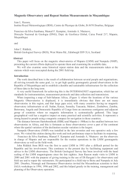
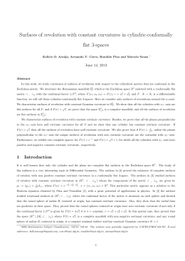
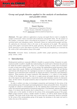
Magnetic field at the symmetry axis of a coaxial pair of coils Nathan Bessa Viana 1 Introduction The purpose of this text is to derive an expression for the magnetic field in the symmetry axis of a coaxial pair of coils. To do that, we consider the field generated by a spire and then sum the contributions of the spires for a fixed coil radius. This result was so used to sum the contributions for different coil radius values and to find the desired expression. 2 Variable definitions In Figure 1 we show a schematic representation of the coils we would like to model. Figure 1: Schematic representation of the coils. Each circle in Figure 1 represents the section of a copper wire used to construct the coils. We assume that each coil has a total of N spires and also that an electric current i is passing trough the wires. The dot in the circle represents the electric current going out the text page and the crosses represent the electric current entering the text page. 3 Magnetic field at the symmetry axis due to one coil We will use the result of the magnetic field generated by a spire in a point located at a distance z from the spire center as a starting point (see Figure 2 bellow). The sense of the magnetic field generated by the spire is ẑ, a unitary vector pointing to the direction of increasing z values. As we are interested in the magnetic field solely in the symmetry axis we do not need to consider the vectorial character of the generated field. The modulus of the magnetic field BSp 1 Figure 2: Spire. generated by the spire of radius a at the point P with distance z from the spire, that has in it an electric current i, is given by [1]: µ0 ia2 BSp = . (1) 2 (a2 + z 2 )3/2 Let us assume now that we have n spires of radius a distributed along a length L, as shown schematically in Figure 3 bellow: Figure 3: Coil with one layer of wires. The coil represented in Figure 3 has just one layer of wires and the reference frame has its origin in the coil center. We define the linear wires density λ by: n . (2) L So the modulus of the magnetic field B1 due to the coil evaluated at the point Q can be written as: λ= µ0 ia2 λ B1 = 2 ! L 2 dz (3) 3 . [a2 + (Z − z)2 ] 2 The sense of the magnetic field is ẑ. Solving the integral and substituting the relation for the wires density (Equation 2) we find: $ $ % % L L Z + Z − µ0 in 2 2 & −& (4) B1 = $ % $ % . 2 2L L L 2 2 2 a + Z+ 2 a + Z− 2 −L 2 2 To proceed with our calculation let us consider now that the spires are distributed in a volume, as shown in Figure 4. Figure 4: Coil with many layers of wires. Considering that we have N spires in the volume marked in grey, we define the volumetric density of spires ρ by: ρ= N . πL(Re2 − Ri2 ) (5) So we have that the number of spires n of one wire layer, with radius r is given by: n = 2πρrLdr, (6) and substituting Equation 6 in Equation 4 we get: $ % $ % L L Z+ 2 Z− 2 µ0 i(2πρrLdr) & dB2 = −& $ % $ % . 2L L 2 L 2 2 2 r + Z+ 2 r + Z− 2 (7) To find B2 we have to integrate Equation 7 with respect to r from Ri to Re . The expression is big but the integration is simple. We should remember that ẑ is the sense of the magnetic field, and after some calculations we find: ) * + * +, µ0 iN L L B2 (Z) = f ,Z − f − ,Z (8) 2 2 L(Re2 − Ri2 ) where - f (ξ, Z) = (Z + ξ)2 1 + 4 * Re Z +ξ +2 − - 1+ * Ri Z +ξ +2 . (9) Magnetic field at the symmetry axis due to the pair of coils Let us define a new axis, x, as described in Figure 5 below: The position x = 0 is in the symmetry axis, exactly in the middle of the two coils. The sense of the magnetic field in the axis is x̂ and the value of the modulus of the magnetic field, B , due to the two coils evaluated at point S is given by: 3 Figure 5: Pair of coils with many layers of wires. * + + L d L d + + x + B2 + −x . 2 2 2 2 Equation 10 is the expression we were looking for. B(x) = B2 5 * (10) Examples As example 1, we show in Figure 6 the values of the magnetic field modulus B (in Gauss) at the symmetry axis of a pair of coils as a function of x (−d/2 < x < d/2, see Figure 5). For this example we have the following characteristic parameters: N = 1000 spires; Ri = 14, 7 × 10⁻³ m Re = 22, 5 × 10⁻³ m L = 8, 0 × 10−3 m; d = 44, 5 × 10⁻³ m; i = 150 × 10−3 A. The magnetic permeability of the vacuum is µ0 = 4π × 10−7 N/A2 [1] and 1G = 10−4 T . As example 2, we show in Figure 7 the values of the magnetic field modulus B (in Gauss) at the symmetry axis of a pair of a Helmholtz (approximately) coil as a function of x. A pair of coils in the Helmholtz condition satisfies the relation: Ri + Re . 2 The coils in example 2 have the following characteristic parameters: d= N = 29 spires; Ri = 28, 7 × 10⁻² m Re = 30, 0 × 10−2 m L = 1, 0 × 10−2 m; d = 35, 0 × 10−2 m; i = 5 A. 4 (11) Figure 6: B as a function of x for the example 1. Figure 7: B as a function of x for the example 2 (approximately Helmholtz coil). 5 Observe that the modulus of the magnetic field at the symmetry axis of the Helmholtz coil, in the region −d/2 < x < d/2, is constant within 5% of variation in the particular case of example 2. References [1] H. M. Nussenzveig, Curso de Fı́sica Básica 3, Edigar Blucher LTDA, 1997. 6
Download