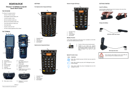
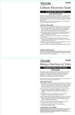
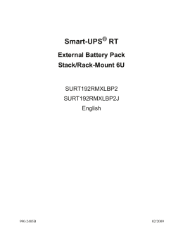
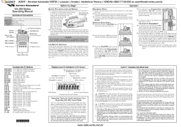
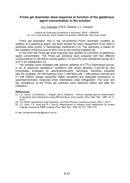
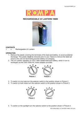
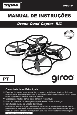
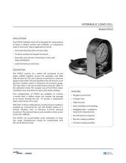
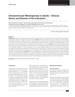
About this Manual
To the best of our knowledge and at the time written, the information contained in
this document is technically correct and the procedures accurate and adequate
to operate this instrument in compliance with its original advertised specifications.
Notes and Safety Information
This Operator’s Manual contains warning symbols which alert the user to check
for hazardous conditions. These appear throughout this manual where applicable, and are defined below. To ensure the safety of operating performance of
this instrument, these instructions must be adhered to.
!
Warning, refer to accompanying documents.
!
Caution, risk of electric shock.
This instrument is designed to prevent accidental shock to the operator when
properly used. However, no engineering design can render safe an instrument
which is used carelessly. Therefore, this manual must be read carefully and completely before making any measurements. Failure to follow directions can result
in a serious or fatal accident.
Technical Assistance
SIMPSON ELECTRIC COMPANY offers assistance Monday through Friday
8:00 am to 4:30 pm Central Time. To receive assistance contact Technical Support or Customer Service at (715) 588-3947.
Internet: http://www.simpsonelectric.com
Warranty and Returns
SIMPSON ELECTRIC COMPANY warrants each instrument and other articles
manufactured by it to be free from defects in material and workmanship under
normal use and service, its obligation under this warranty being limited to making
good at its factory or other article of equipment which shall within one (1) year
after delivery of such instrument or other article of equipment to the original
purchaser be returned intact to it, or to one of its authorized service centers, with
transportation charges prepaid, and which its examination shall disclose to its
satisfaction to have been thus defective; this warranty being expressly in lieu of
all other warranties expressed or implied and of all other obligations or liabilities
on its part, and SIMPSON ELECTRIC COMPANY neither assumes nor authorizes any other persons to assume for it any other liability in connection with the
sales of its products.
This warranty shall not apply to any instrument or other article of equipment
which shall have been repaired or altered outside the SIMPSON ELECTRIC
COMPANY factory or authorized service centers, nor which has been subject to
misuse, negligence or accident, incorrect wiring by others, or installation or use
not in accord with instructions furnished by the manufacturer.
2
NOTES
3
Contents
1. INTRODUCTION ............................................................................... 7
1.1
1.2
1.3
GENERAL DESCRIPTION ................................................................. 7
Items And Accessories ....................................................................... 7
Technical Data .................................................................................... 7
2. PREPARATION FOR USE ................................................................. 8
2.1
2.2
2.3
2.4
2.5
Unpacking And Inspection ................................................................. 8
Warranty ............................................................................................. 8
Shipping ............................................................................................. 8
Power Requirements .......................................................................... 8
Care Of The Instrument ....................................................................... 9
3. OPERATION ...................................................................................... 9
3.1
3.2
3.3
3.4
Precautions ......................................................................................... 9
Operational Features And Items ...................................................... 10
Effects Of Atmospheric Pressure And Temperature ......................... 11
Calibration Of The 897 Noise Dosimeter ......................................... 11
4. SERVICING INSTRUCTIONS .......................................................... 12
4.1
4.2
Lo-Battery Indication ........................................................................ 12
Battery Replacement ........................................................................ 13
4
NOTES
5
NOTES
6
1.
INTRODUCTION
!
Never place the operating calibrator tightly against the ear. The high sound level
present could be harmful, especially to someone with a hearing deficiency.
1.1
GENERAL DESCRIPTION
The Simpson 887-2 Sound Level Calibrator (hereafter referred to as the 887-2, or
simply the Instrument) is an accurate, portable sound source designed specifically for convenient field calibration of the Simpson 897 Noise Dosimeter (hereafter referred to as the Noise Dosimeter). Its compact, rugged construction and
battery-powered operation permit its use in virtually any location.
When acoustically coupled to a Noise Dosimeter, the 887-2 provides a constant,
calibrated, sound pressure level of 114 dB or 94 dB (0 dB reference is 20 µPascals) at the microphone of the Noise Dosimeter. The sound pressure accuracy is
±0.5 dB at 23°C and 760 mmHg. The sound frequency is 1,000 Hz. The case of
the Instrument is constructed of aluminum and designed to minimize loss when
coupling the transducer cavity to the noise Dosimeter microphone.
1.2
Items And Accessories
All items and accessories required for the operation of the 887-2 are furnished
with each instrument, and listed in the following table.
Table 1-1. Items and Accessories Furnished With This Instrument
Quantity
1
1
1
Description
Screwdriver
9V battery, NEDA 1604
Operator’s Manual
Part Number
5-116470
5-114907*
6-115263
*Available from local retail stores.
1.3
Technical Data
Table 1-2 lists the technical specifications for the Simpson 887-2 Sound Level
Calibrator.
Table 1-2. Technical Data
1. Acoustic Output
Frequency:
1000 Hz ±1%
Sound Pressure Level:
114 dB or 94 dB (switch selectable)
(Reference: 0 dB = 20 µPascals)
2. Accuracy:
±0.5 dB at reference conditions.
3. Distortion:
Less than 1%
4. Temperature Range:
0° to +50°C (operating) -40° to 60°C
(storage, battery removed)
5. Output Temperature
Coefficient:
Less than ±0.05 dB/°C
7
6.
7.
8.
Operating Relative
Humidity:
Power Requirements:
Battery Life:
9.
Reference Conditions:
0 to 90%
One 9V battery, NEDA 1604
Approximately 100 hours for 2 hours per
day operation.
23°C, 760 mmHg, 30% to 60% Relative
Humidity.
Aluminum case includes acoustic cavity
and provides shielding. Electronic circuits are packaged on a single printed
circuit board.
13.5 oz (0.35 kg)
5-1/4" long, 2" diameter (131 mm long,
50 mm diameter)
10. Mechanical Construction:
11. Weight:
12. Dimensions:
2.
PREPARATION FOR USE
This section contains information and instructions for the packaging and shipping of the 887-2. Included are unpacking and inspection procedures, warranty,
shipping, and power requirements.
2.1
Unpacking And Inspection
Examine the shipping carton for obvious signs of damage. If shipping carton is in
good condition, inspect the Instrument for possible damage incurred during shipment. If damaged, notify the carrier and supplier and do not attempt further use of
the Instrument. If the Instrument appears to be in good condition, read Operator’s
Manual in its entirety. Become familiar with the Instrument as instructed in the
manual, then proceed to check the electrical performance as soon as possible.
Also, check that all items listed in Table 1-1 are included with the Instrument.
2.2
Warranty
The Simpson Electric warranty policy is printed on the inside front cover of this
manual. Read it carefully before requesting a warranty repair. For assistance of
any kind, including help with the Instrument under warranty, contact the factory.
Give full details of the difficulty and include the Instrument model number, serial
number and date of purchase. Service data or shipping instructions will be sent
to you promptly. If an estimate of charges for non-warranty or other service work
is required, a maximum charge estimate will be quoted. This charge will not be
exceeded without your prior approval.
2.3
Shipping
Pack the Instrument carefully and ship it prepaid to the proper destination. Insure
the Instrument.
2.4
Power Requirements
The 887-2 is powered by one 9V battery (supplied). Refer to Table 1-2, items 7
and 8, for description and paragraph 4.2 for replacement. The battery is packaged separately.
8
2.5
Care Of The Instrument
a.
b.
c.
d.
e.
f.
g.
3.
Immediately clean any spilled materials from the Instrument and wipe dry. If
spillage is corrosive, use a suitable cleaner to remove it and to neutralize
corrosive action.
Remember to turn off the Instrument when not using it.
Avoid prolonged exposure or usage in areas subject to temperature and
humidity extremes, vibration, mechanical shock, dust, corrosive fumes, and
strong electrostatic and electromagnetic interference.
Be sure the transducer cap is firmly in place.
If the Instrument has not been used for 30 days, check battery for leakage,
and replace if necessary.
It is recommended that the Instrument be returned to the factory annually
(sooner if required) for a complete overall check, adjustment, and calibration.
When the Instrument is not in use, store it in a room free from temperature
extremes, dust, corrosive fumes, mechanical vibration, or shock. If storage
time is expected to exceed 30 days, remove the battery.
OPERATION
This section contains the necessary instructions required for operating the 887-2.
3.1
Precautions
The 887-2 is intended for use in conjunction with the Simpson Noise Dosimeters.
!
When the 887-2 is turned on, a 1000 Hz tone is audible. Under this condition,
there is a natural tendency to bring the Instrument against the ear. However,
never place the operating calibrator tightly against the ear. The high sound level
present could be harmful, especially to someone with a hearing deficiency.
Carefully review and become thoroughly familiar with the contents of the
Operator’s Manual for the Noise Dosimeter (precautions, operating notes, specifications, etc.).
Check the calibration of the 887-2 periodically or whenever accuracy is doubted.
For example, inspect the Instrument for evidence that might indicate that it has
been subjected to severe mechanical shock or environmental extremes. This
check can be made by comparison with another 887-2 Calibrator, or with a reference Noise Dosimeter known to be accurate. If another 887-2 or reference Noise
Dosimeter is not available, return the Instrument to the factory for a complete
overall check.
Be sure the sealing ring in the transducer cap is not damaged and that the leakto-atmosphere hole is not clogged. (Refer to Table 3-1, item 4.)
9
3.2
Operational Features And Items
All features and items used to operate the 887-2 calibrator are described in Table
3-1 and illustrated in Figure 3-1.
4
887-2
SOUND LEVEL CALIBRATOR
OUTPUT FREQUENCY: 1000 HERTZ
3
ON
114 dB
OFF
ON
94 dB
2
LOW BATTERY
CAUTION
NEVER PLACE CALIBRATOR AGAINS EAR.
READ OPERATOR'S MANUAL.
SIMPSON ELECTRIC CO., ELGIN IL 61020
MADE IN USA
1
Figure 3-1. Model 887-2
Table 3-1. Operational Features and Items
1.
Battery Cap:
2.
Lo Batt Indicator (LED):
3.
OFF/ON
(94 or 114 dB select
switch)
4.
Transducer Cap:
This is an aluminum cap which screws into one
end of the Instrument housing. It provides easy
access to the battery compartment and also holds
the battery firmly in position.
A small light-emitting diode (LED) indicator will
light if the battery needs to be replaced. The Instrument will automatically shut-down if the battery condition is not adequate to provide the specified sound level pressure.
This 3-position slide switch is used to turn the
Instrument on and select either 94 or 114 dB sound
pressure output levels.
This is a precisely machined cap which screws
into the other end of the housing. The mating of
the transducer cap and the microphone of the
Sound Level Meter being calibrated constitutes
an acoustic coupler. The cap includes a sealing
ring to ensure a closed cavity between the cap
and Sound Level Meter microphone. A small hole
provides a controlled leak to the atmosphere. This
cap must be tight when using the calibrator. The
accuracy of the calibration is questionable if the
transducer cap is loose.
10
3.3
Effects Of Atmospheric Pressure And Temperature
114
113.5
113
112.5
112
SEA LEVEL
CALIBRATOR OUTPUT LEVE (dB SPL)
For any one location, the effects of normal variations of atmospheric pressure are
usually negligible. The effect of elevation is shown in Figure 3-2. This graph
shows the change in Instrument output level compared to that obtained at sea
level. For example, if the Instrument is being used at 7500 feet, calibrate the
Noise Dosimeter for an indication of 113.5 for the 897 Dosimeter.
The effects of temperature are less than ±0.05 dB/°C (reference is 23°C).
111.5
111
mmHg 760 750 700
650
600
550
500
400
450
350
300
INCHES Hg
28
30
FEET ABOVE
SEA LEVEL
(THOUSANDS) 0 1 2
26
24
22
4
6
8
18
20
10
12
16
14 16
14
18 20
Figure 3-2. Effect of Elevation Upon Calibrator Output
3.4
Calibration Of The 897 Noise Dosimeter
To calibrate the 897 Noise Dosimeter using an 887-2 calibrator:
a.
If using the windscreen, remove and carefully insert the microphone fully
into the acoustic cavity of the calibrator (Figure 3-3).
b. Set the calibrator power switch to the “ON” position (Figure 3-3) and check
that the calibrator battery is okay. (Refer to paragraph 4.1.)
NOTE: It is normal for the sound level of this Instrument to take a few seconds to
“ramp up” to the specified output level after it is first switched on. The LO-BATTERY indicator may blink briefly during this time.
c. Set the “OFF-RUN-HOLD” slide switch in the 897 to the “RUN” position. Wait
until the Display Test sequence is completed, then depress the SPL (CAL)
switch (Figure 3-3).
d. Select the desired range. For checking at 94 dB use the 50/100 range; for
checking at 114 dB use the 80/130 range.
11
FULLY INSERT
MICROPHONE
897
SET TO "114dB"
POSITION
DOSIMETER
SOUND MEASURING SYSTEM
887-2
SOUND LEVEL CALIBRATOR
OUTPUT FREQUENCY: 1000 HERTZ
SET TO "RUN"
ON
OFF RUN HOLD
LOCK
114dB
OFF
ON
PRESS
"CAL"
94 dB
LOW BATTERY
CAUTION
SPL
"CAL"
INT
(60 sec)
TEST
SETUP
DOSE
PEAK
Leq
MAX
TIME
PRINT
NEVER PLACE CALIBRATOR AGAINS EAR.
READ OPERATOR'S MANUAL.
SIMPSON ELECTRIC CO., ELGIN IL 61020
MADE IN USA
SIMPSON ELECTRIC CO. ELGIN , IL 60120
Figure 3-3. 897 Dosimeter Calibration
e.
f.
g.
4.
If calibration is required, using the screwdriver supplied with the calibrator,
turn the adjustment control until a reading of either 94.0 dB or 114.0 dB is
indicated on the display.
(Optional) The time and date of this calibration may be recorded in the memory
of the 897 by pressing and holding the “SPL (CAL)” switch until the display
flashes “CAL”. Only the two most recent dates will be stored in the memory of
the 897.
Turn off the calibrator. Remove the microphone and replace the windscreen.
SERVICING INSTRUCTIONS
The 887-2 contains no operator-serviceable parts, except for the battery. This
section contains instructions for replacing the battery. Special training and facilities are required for servicing and calibrating sound level calibrators. Whenever
the Instrument does not appear to be functioning properly, send it to the factory.
4.1
Lo-Battery Indication
The Instrument will function according to specifications for approximately eight
hours after the time the LO-BATTERY indicator initially lights up; after which time,
a “dead battery” detection circuit will automatically shut down the Instrument. The
LO-BATTERY indicator will remain on and the battery must be replaced to restore
the Instrument to normal operation.
12
4.2
Battery Replacement
To replace the battery:
a.
b.
c.
d.
e.
Turn off the calibrator.
Remove the battery cap (Table 3-1, item 1) by turning it counterclockwise.
Pull battery from the compartment and unsnap the connector. (Note routing
of the connector cable with respect to the battery.)
Snap the battery connector onto the mating terminals of the replacement
battery. (The connector is polarized so it only can be connected one way.)
Slide the battery into the battery compartment. Turn the battery so the connector is facing outward. Tuck the connector cable neatly under the battery
so it will not interfere when the battery cap is replaced.
13
NOTES
14
NOTES
15
SIMPSON ELECTRIC COMPANY 520 Simpson Avenue
Lac du Flambeau, WI 54538-0099 (715) 588-3947 FAX (715) 588-1248
Printed in U.S.A.
Part No. 06-115263 Edition 6, 01/07
Visit us on the web at: www.simpsonelectric.com
16
Download