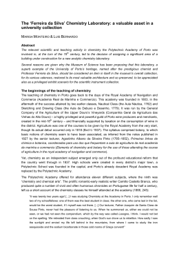
Electronic Supplementary Material (ESI) for Journal of Materials Chemistry A This journal is © The Royal Society of Chemistry 2013 Supporting Information Biphasic Oxidation promoted by Magnetic Amphiphilic Nanocomposites undergoing a Reversible Emulsion Process Ivo Freitas Teixeira, Aline Almeida da Silva Oliveira, Taís Christofani and Flávia Cristina Camilo Moura Experimental Preparation and Characterization of the MANCs Nano-alumina was impregnated with iron nitrate III (Fe(NO 3)3.9H2O - Vetec) and ammonium molybdate ((NH4)6Mo7O24.4H2O – Rio Lab) in different proportions: a group of samples with 10, 5 and 1 % wt of Fe, another with Fe10%Mo1%, Fe5%Mo0.5% and Fe1%Mo0.1%. The impregnated matrix (200 mg) was submitted to a previous temperature programmed reduction (TPR) with H2/N2 (5% H2) up to 900oC. After cooling of system, samples were submitted to TPCVD process (Temperature Programmed Chemical Vapor Deposition) with methane heating up to 900oC (Figure S1). This temperature was kept for an hour. For both experiments, TPR and TPCVD, gas flow was 80 mL min -1 and heating rate 10oC min-1. The materials produced were named MANCs (Magnetic Amphiphilic Nanocomposites). 1 Electronic Supplementary Material (ESI) for Journal of Materials Chemistry A This journal is © The Royal Society of Chemistry 2013 Fe3+ + MoO42-/ Alumina Fe0 + Mo0/ Alumina Forno Oven(900 oC) Fe0 + Mo0/ Alumina Oven (900 oC) Forno Fe0 + Mo0 + C/ Alumina Figure S1. Schematic synthesis of the amphiphilic materials. The MANCs were characterized by Temperature Programmed Reduction - TPR (Quanta Chrome CHEMBET-3000), X-ray diffraction – XRD (difratometer Rigaku D\MAX ÚLTIMA), Mössbauer spectroscopy (spectrometer convencional CMTE MA250, constant acceleration, 57 Co source in Rh matrix, room temperature), magnetization measurements (magnetometer LakeShore 7404 VSM System), thermal analysis – TG (Shimadzu TGA-60, heating rate of 10oC min-1, air flow of 100 mL min-1), elemental analysis CHN (CHN Perkin-Elmer analyzer), Raman spectroscopy (DeltaNu ExamineR, excitation wavelengths of 532 nm (green laser) and 785 nm (red laser)), scanning electron microscopy – SEM (microscope SEG - Quanta 200 – SEI), EDS micro-analysis (EDAX), transmission electron microscopy – TEM (microscope Tecnai G2 200kV – SEI) and BET surface area and porosity (Autosorb 1 Quantachrome). Interface promotion The behavior of the MANCs as emulsifiers was evaluated with two immiscible mixtures (25/75%): water/soy bean and water/decalin. The amphiphilic composites (500 mg L -1) were added to the mixtures and the systems were sonicated (Thornton t-14) for 5 minutes resulting in 2 Electronic Supplementary Material (ESI) for Journal of Materials Chemistry A This journal is © The Royal Society of Chemistry 2013 stable emulsions which were analyzed by optical microscopy (Cole Parmer Instrument, 4150050). The amphiphilic composites were also tested as demulsifiers with a stable emulsion of methyl soybean biodiesel (70%) and water. The materials were dispersed rapidly in the emulsion and after were dragged by an external magnetic field. The separation of the phases promoted by the composites was monitored over time. Reactions in Biphasic Systems The capacity of the amphiphilic materials to emulsify and demulsify was used to turn feasible Fenton reactions, in which the oxidant (hydrogen peroxide – H2O2) is in the aqueous phase and the substrate in the organic phase. Heterogeneous Fenton like reactions were tested, in which the iron phases on the surface of the MANCs act in H2O2 decomposition. Model contaminants for sulfur and nitrogen compounds present in petroleum were tested, e.g. quinolone and dibenzothiophene (DBT). Experiments were carried out with organic contaminated solutions 500 ppm N or S (for quinoline and DBT, respectively) in cyclohexane (5 mL). The MANCs were initially added to organic solution (20 mg) and left in contact before addition of the oxidant in order to reach equilibrium adsorption. After 24h, 1 mL of H 2O2 30% was added to the system. The removal of contaminants, as well as the formation of oxidation products, was monitored by gas chromatography with Flame Ionization Detector (GC-FID, SHIMADZU GC17A) and by gas chromatography coupled to mass spectrometry (GC-MS, SHIMADZU QP2010 – PLUS). Oxidized products extracted by aqueous phase were monitored by mass spectrometry with electrospray ionization (Agilent ion trap mass spectrometer). Additionally, leaching of metals present in the MANCs was monitored by atomic absorption spectrometry. 3 Electronic Supplementary Material (ESI) for Journal of Materials Chemistry A This journal is © The Royal Society of Chemistry 2013 Results and discussion Preparation and Characterization of the MANCs Nano-alumina impregnated with different Fe/Mo ratios were submitted to a temperature programmed reduction (TPR) (Figure S2a) and further to a temperature programmed chemical vapor deposition (TPCVD) (Figure S2b) to produce the amphiphilic materials. The records of Figure S2a refer to hydrogen consumption over heating for the pre-reduction of metallic phases. On the other hand, the records of Figure S2b refer to hydrogen production for TPCVD experiment. Alumina AFe1% AFe5% AFe5%Mo0.5% AFe1%Mo0.1% AFe10% AFe5% AFe10% H2 production/a.u. H2 consumption/a.u. AFe10%Mo1% AFe1%Mo0.1% AFe5%Mo0.5% AFe10%Mo1% AFe1% Isothermal Alumina 0 200 400 600 Temperature/oC 400 800 600 (a) 800 1000 1200 1400 o Temperature/ C 1600 (b) Figure S2. (a) TPR and (b) TPCVD profiles for amphiphilic materials prepared from nanoalumina, Fe/Mo and CH4. TPR analysis (Figure S2a) of the materials prepared without molybdenum showed profiles with three intense peaks related to the reduction of different iron phases. Peaks around 300, 400 and 800oC are related to the reduction of Fe3+ to Fe2+ and Fe0 gradually [1]. 4 Electronic Supplementary Material (ESI) for Journal of Materials Chemistry A This journal is © The Royal Society of Chemistry 2013 For the group of MANCs which have Mo on the surface, a shift of the peaks is observed tending to increase the temperature of iron reduction, suggesting that there is an interaction between Fe and Mo species. The influence of molybdenum in the TPR profiles is slight because of its low content in the sample composition. In the TPR profile obtained for sample AFe10%Mo1% it is possible to observe a peak shoulder at around 320 oC, a small peak at 580oC and a broadening of the peak between 700 and 800 oC. The low-temperature peak can be assigned to the partial reduction (Mo6+ → Mo4+) of Mo oxides or heteropolymolybdates (octahedral Mo species) [2]. The high-temperature peak at around 800oC comprises the deep reduction of all Mo species, including highly dispersed tetrahedral Mo species. The peak at 580oC may be due to the intermediate-reducible crystalline phases of orthorhombic MoO3 [2]. During TPCVD process CH4 decomposes in the presence of the metals on the surface of the material depositing solid carbon and releasing H2 gas. Therefore in Figure S2b the area above the curve is proportional to the amount of carbon deposited on the materials surface. The phases Fe0 and Mo0 act as catalysts in the activation and decomposition of CH4 and formation of carbon, especially in the organized form of filaments and nanotubes. Summarizing, the greater the reduction of metallic phases, the more organized carbon structures should be deposited on the materials surface. The influence of Mo in the carbon deposition is clear in TPCVD curves that show that H2 production is much larger for samples containing Mo. The more symmetric and thinner the TPCVD peak, the more organized and homogeneous the carbon formed. The MANCs prepared with nano-alumina and methane with different contents of Fe and Mo were initially analyzed by DRX (Figure S3). The obtained X-ray diffraction patterns show that the composition of samples prepared with 1 and 5% of Fe do not vary significantly, neither in those samples with molybdenum. It is also observed that peaks relating to alumina with 2Ɵ between 65 and 70o undergo some changes for sample AFe5%Mo0.5%, suggesting that this composite may be coated by organized carbon structures which exhibit a different diffraction 5 Electronic Supplementary Material (ESI) for Journal of Materials Chemistry A This journal is © The Royal Society of Chemistry 2013 pattern and interfere on alumina diffraction. Samples with 10% of Fe present almost only peaks related to iron carbide, metallic iron and carbon. Peaks related to alumina have further their intensity reduced, especially for sample AFe10%. In general X-ray diffraction patterns for samples with higher metal contents demonstrate that they become less crystalline than the others, presenting fewer peaks and peaks less defined. This result suggests that the carbon deposited on the surface of materials with 10% Fe is poorly organized. Molybdenum phases could not be observed due to its low concentration and high dispersion on the materials surface. Relative intensity/a.u. A = Al2O3 AFe1% C = Cgraf A C A Fe = Fe A 0 CFe = Fe3C CFe Fe A A CM = Mo2C A C AFe1Mo0.1% AFe5% CM AFe5Mo0.5% AFe10% AFe10Mo1% 10 20 30 40 50 60 70 80 2 Figure S3. X-ray diffraction patterns obtained for the composites produced. Mössbauer spectra (Figure S4) were obtained for all the amphiphilic materials produced from nano-alumina. Based on the hyperfine parameters generated for each sample (Table 1) it was possible to determine their iron composition. Figure S5 summarizes the iron phase composition obtained for the amphiphilic materials. 6 Electronic Supplementary Material (ESI) for Journal of Materials Chemistry A This journal is © The Royal Society of Chemistry 2013 1,00 1,000 0,998 A-Fe1% A-Fe1%Mo0,1% 0,996 Trasmissão Relativa Transmissão Relativa 0,98 1,000 0,995 0,990 A-Fe5% 0,985 -Fe(C)) Fe3C Fe-Al(desordenado) 1,00 Fe 1,000 0,995 A-Fe5%Mo0,5% -Fe(C) Fe3C 0,990 Fe-Al (desordenado) Fe Fe7C3/Fe5C3 1,00 0,98 A-Fe10% 0,99 0,96 0,94 -12 -9 -6 -3 0 3 Velocidade/mm s 6 9 12 A-Fe10%Mo1% 0,98 -12 -9 -1 -6 -3 0 3 6 9 12 -1 Velocidade/mm s Figure S4. Mössbauer spectra obtained of the amphiphilic materials of nano-Al2O3. Table S1. Hyperfine parameters used for the determination of phases presented in all samples of amphiphilic materials produced with alumina. Sample AFe1% AFe1%Mo0,1% AFe5% AFe5%Mo0,5% AFe10% AFe10%Mo1% Site/Phase Fe3C Fe-Al -Fe(C) Fe3C -Fe(C) Fe-Al Fe Fe3C Fe-Al Fe -Fe(C) Fe3C Fe5C3/Fe7C3 -Fe(C) Fe-Al Fe3C Fe-Al Fe Fe3C Fe5C3/Fe7C3 -Fe(C) Fe- Al / mm s-1 Q / mm s-1 (0.05) 0.14 0.17 -0.04 0.19 0.05 0.19 0.00 0.17 0.16 0.10 0.00 0.19 0.16 -0.05 0.16 0.17 0.16 0.00 0.18 0.17 -0.04 0.16 (0.05) - 0.02 0.65 0.04 0.89 0.00 0.07 0.85 0.00 0.03 0.00 0.78 0.07 0.80 0.00 0.03 0.10 0.80 Bhf / T (0.05) 20.08 20.2 33 20.2 33 20.3 17.4 22.2 33 20.3 17.6 - Area / % 74 20 6 87 2 7 4 73 9 9 9 50 27 6 17 91 6 3 59 28 2 11 7 Iron phases distribution/% Electronic Supplementary Material (ESI) for Journal of Materials Chemistry A This journal is © The Royal Society of Chemistry 2013 Fe Fe5C3/Fe7C3 80 Fe3C Fe-Al Fe(C) 60 40 20 0 1% e1% o0. AF M e1% AF 5% e5% o0. AF M e5% AF % 1% e10 Mo AF % e10 AF Figure S5. Iron phase composition obtained by Mössbauer of amphiphilic materials. In agreement with previous XRD results, Mössbauer analysis showed the formation of large amounts of iron carbide (Fe3C) in all samples that may be associated with the high temperature at which the materials were produced. At 900 oC all iron phases in contact with methane should be reduced to iron carbide. Other characterized phases are alloys involving Fe, Al and C. It is observed that the presence of molybdenium favor the formation of carbides in all samples. In Figure S6 are shown the hysteresis loops and the saturation of magnetization (in detail) measured for all different amphiphilic materials produced. 8 Electronic Supplementary Material (ESI) for Journal of Materials Chemistry A This journal is © The Royal Society of Chemistry 2013 9 AFe1% Mo0,1% AFe5% Mo0,5% AFe10% Mo1% M/emu g -1 6 3 0 30 AFe10% 25 -3 M/emu g -1 20 -6 15 10 AFe10%Mo1% AFe5% 5 AFe1% AFe5%Mo0,5% AFe1%Mo0,1% 0 -9 Materiais anfifílicos -15 -10 -5 0 5 10 15 H/kOe Figure S6. Magnetic hysteresis curves and saturation magnetization (in detail) for all the amphiphilic materials. Table 2 shows data of MS (saturation), MR (remanence) and MR/MS (squareness) obtained for all the amphiphilic materials in order to study the effect of Mo addition in the magnetic properties of the materials. 9 Electronic Supplementary Material (ESI) for Journal of Materials Chemistry A This journal is © The Royal Society of Chemistry 2013 Table S2. Effect of Mo addition on the magnetic properties of amphiphilic materials produced with different Fe concentrations. Sample MS (emu g-1) MR (emu g-1) S=MR/MS AFe1% 1.04 0.44 0.42 AFe1%Mo0,1% 1.04 0.13 0.12 AFe5% 4.72 1.55 0.33 AFe5%Mo0,5% 4.72 1.24 0.26 AFe10% 28.08 5.99 0.21 AFe10%Mo1% 7.34 1.70 0.23 Two important steps of the synthesis of the MANCs are: (i) the impregnation of nanoalumina with iron and molybdenum, and (ii) the reduction of these metals. Nano-alumina, the starting material for the synthesis of the amphiphilic materials is not magnetic. However, as Fe 0 has large saturation magnetization ( 218 emu g-1), amphiphilic materials containing even just 1% of iron exhibit a magnetic hysteresis. The magnetization curves of the amphiphilic materials showed that, as expected, their saturation magnetization as well as the magnetic susceptibility () increased with the Fe content. Regarding the removal of the magnetic particles from a catalytic reaction by means of the application of a magnetic force, this magnetic force will be proportional to the field gradient applied and to the magnetic moment of the particles. Hence, the magnetic force acting in the particle will be proportional to its magnetic susceptibility. In consequence if the field applied is sufficient to saturate the particle then the magnetic force will be proportional to the saturation magnetization of the particle [3]. From magnetization measurements it is observed that the presence of molybdenum does not modify the saturation magnetization of composites with 1 and 5% Fe, which is of 1.1 and 4.7 10 Electronic Supplementary Material (ESI) for Journal of Materials Chemistry A This journal is © The Royal Society of Chemistry 2013 emu g-1, respectively. However, with the increase of Fe content to 10%, the results suggest the presence of Mo produces a four-fold reduction of the saturation magnetization, since the sample AFe10% has magnetization of 28.1 emu g-1 while for sample AFe10%Mo1% it is 7.3 emu g-1. The reduction of the ferromagnetic nature of the samples due to Mo addition is larger for low Fe concentrations characterized by the squareness parameter (S). S is defined as the ratio of remanence magnetization (MR) to saturation magnetization (MS). These indicates that the addition of Molybdenum has a lower overall effect on the magnetic properties of samples with 5%Fe, having a similar magnetic performance at zero applied field than those samples with Fe10%Mo1%. The magnetic properties of the MANCs are strategic and very important for the intended application. Being magnetic, the amphiphilic materials can be removed easily from a reaction system after catalysis by application of a magnetic field gradient. Those materials exhibiting larger magnetic moments may be able to follow the magnetic field gradient and be pulled into the strongest magnetic field region facilitating their removal. The carbon content was determined by elemental analysis (Figure S7). The carbon content for the different amphiphilic composites varies from 2 to 16% for composites AFe1% and AFe10%, respectively. In general, the increase of catalysts concentration (Fe/Mo) on alumina surface is responsible for an increment on the amount of carbon deposited by CVD reaction with methane, as expected based on TPCVD experiments. 11 Electronic Supplementary Material (ESI) for Journal of Materials Chemistry A This journal is © The Royal Society of Chemistry 2013 18 16 Carbon content/% 14 12 10 8 6 4 2 0 % e1% o0,1 A-F %M 1 e A-F % % e5% o1% e10 o0,5 A-F A-F 0%M %M 1 5 e e F AA-F A Figure S7. Carbon content of the MANCs obtained by CHN. In order to characterize the carbon deposits formed after TPCVD of nano-Al2O3, Fe/Mo and CH4, Raman spectra were obtained for MANCs. Figure S8 shows Raman spectra ( = 532 D/G =1.26 AFe1% D/G =0.46 AFe1% Mo0.1% D/G =0.10 AFe5% D/G =0.13 AFe5% Mo0.5% D/G =0.40 AFe10% D/G =0.40 AFe10% Mo1% Intensidade relativa/u.a. Relative intensity/u.a nm) obtained for the MANCs. Fe2O3 AFe1% AFe1%Mo0.1% 1,2 nm AFe5% 1,1 nm AFe5%Mo0.5% AFe10% AFe10%Mo1% 1200 1400 1600 -1 Raman shift / cm 1800 (a) 150 200 250 300 350 400 450 500 -1 Raman shift/cm (b) Figure S8. Raman spectra of the different MANCs produced. 12 Electronic Supplementary Material (ESI) for Journal of Materials Chemistry A This journal is © The Royal Society of Chemistry 2013 Two important bands can be observed in the spectra of Figure S8a. The D band (1340 cm-1) is characteristic of defective or disorganized carbon structures, such as amorphous carbon, while the G band (1580 cm-1) is related to well organized graphitic structures, i.e. carbon nanotubes and nanofibers [4]. The D/G ratio indicated in Figure S8a is the ratio between the intensities of D and G band. The smaller this ratio, the more organized the carbon structure formed on the materials surface. It is observed that the D/G ratio is significantly less for samples with 5% iron, with or without molybdenum. The other samples exhibit D/G ratio very similar. Therefore it can be said that samples AFe5% and AFe5%Mo0.5% have higher content of graphitic structures that may include carbon nanotubes and carbon nanofibers. The influence of Mo on the formation of organized carbon structures is clear in the situation of less Fe content: D/G ratio decreases from 1.26 to 0.46 for AFe1% and AFe1%Mo0.1%, respectively. With the increase of iron catalytic sites, Mo makes no significant influence, what can be related to the greater action of Fe as catalyst of CH4 decomposition. It is possible to say that D/G ratios for composites with 5 and 10% of Fe with or without Mo is the same, 0.1 and 0.4, respectively. Another important region of a Raman spectrum for the characterization of graphitic structures is between 150 and 300 cm -1. In this range are found RBM (Radial Breathing Mode) bands related to the movement of all carbon atoms of a cylindrical structure (such as a nanotube) vibrating in the radial direction with the same phase (totally simetric) as if the tube was breathing. These bands can only be detected for single-walled carbon nanotubes and are related to the tube diameter. Figure S8b shows the spectra obtained for all the amphiphilic materials in the region of low frequency using the red laser ( = 785 nm). The RBM bands identified in Figure S8b around 200 and 230 cm-1 are related to the formation of single-walled carbon nanotube (SWCNT) with estimated diameters of 1.1 and 1.2 nm [5,6]. SWCNT can be found in small amount on the sample AFe1%Mo0.1% and more significantly on samples with 5% of Fe, which also have the lowest D/G ratios ( 0.10). This information shows indirectly that the size of the Fe particles or FeMo are much smaller in these samples than in the others, since 13 Electronic Supplementary Material (ESI) for Journal of Materials Chemistry A This journal is © The Royal Society of Chemistry 2013 SWCNT are produced only from particles of diameter between 1 and 5 nm [7]. This could explain a better activity of these two samples in the catalysis of biphasic system reactions, described further in this paper. The broad and little intense band that appears about 350 cm -1 can be attributed to the formation of iron carbide [8]. Figure S9 shows some SEM images obtained of nano-alumina, AFe1%, AFe5%, AFe5%Mo0.5% and AFe10%. SEM images obtained of pure nano-alumina showed that this matrix presents a structure similar to nano rods of Al2O3. When this matrix is submitted to CVD with methane in the absence of metal catalysts it is suggested by SEM and EDS that carbon is deposited on its surface in the form of amorphous carbon (Figure S9). The SEM images of the samples prepared by TPCVD of alumina, Fe/Mo and CH4 showed interesting results regarding the formation of carbon deposits. In the presence of Fe e Mo, organized carbon structures are produced during the CVD process. The morphology characteristic of the matrix is maintained but images suggest the existence of carbon filaments and metal nanoparticles coated with graphitic carbon. Both nanoparticles and filaments present diameters around 50 nm. 14 Electronic Supplementary Material (ESI) for Journal of Materials Chemistry A This journal is © The Royal Society of Chemistry 2013 Nano Al2O3 1,0 µm AFe5%Mo0.5% 500 nm AFe5% 300 nm AFe10% 300 nm Figure S9. Images obtained by SEM of the MANCs AFe1%, AFe5%, AFe5%Mo0.5% and AFe10%Mo1%. It is known that iron and molybdenum catalyze the deposition of carbon as organized structures, such as nanotubes, nanofibers and graphite [9-11]. Thus, the greater the metals content it is expected a higher formation of nanotubes and nanofibers. However, it was not possible to observe these structures in samples with 10% of iron by SEM. Due to this fact, composites AFe10% and AFe10%Mo1% were analyzed in more detail by transmission electron microscopy (TEM) in order to verify if carbon structures with nanometric diameters were formed. Images obtained by TEM for samples AFe10% and AFe10%Mo1% show single and double-walled carbon nanotubes with diameters of approximately 5 nm (Figure S10). There are also nanoparticles of 10 nm average completely coated. The interplanar distance of the material that coats the nanoparticles was measured at 3.5 Å, very similar to the theoretical value of graphite carbon, which is 3.35 Å. It is observed that for these samples, more filaments are 15 Electronic Supplementary Material (ESI) for Journal of Materials Chemistry A This journal is © The Royal Society of Chemistry 2013 produced in the presence of molybdenum. These structures of nanometric size could not be seen by SEM due to the low resolution of this technique compared to TEM. Figure S10. Images obtained by TEM of samples AFe10% and AFe10%Mo1%. Measurements of specific surface area and porosity were carried out through N2 adsorption by the BET method for nano-alumina and the amphiphilic products. The specific surface area of pure alumina is 46 m 2 g-1 and most of the amphiphilic materials present surface area around 50 m2 g-1 unless AFe5%Mo0.5% with area of 128 m2 g-1 probably due to the higher formation of carbon filaments in this sample. Interface promotion Mixtures of water with soybean oil or decalin were sonicated for 1 min. The natural mixtures are heterogeneous, i.e. the two phases remain separated even after sonication. However stable emulsions are formed between soil bean oil or decalin with water in the presence of the amphiphilic materials. The produced MANCs are very efficient favoring the 16 Electronic Supplementary Material (ESI) for Journal of Materials Chemistry A This journal is © The Royal Society of Chemistry 2013 formation and stabilization of oil droplets in the aqueous phase because they remain on the interface oil/water, avoiding the droplets coalescence. Images obtained by optical microscopy show the formation of emulsions with the solid emulsifiers on the interface of the disperse droplets. Figure S11 presents images of emulsions formed between decalin and water for samples AFe5% and AFe5%Mo0.5%. AFe5%Mo0.5% AFe5% Figure S11. Images obtained by optical microscopy of the emulsions promoted by the MANCs prepared. The MANCs were also tested in the separation of a stable emulsion of biodiesel and water. This emulsion is formed naturally during biodiesel synthesis due to the coproduction of soaps that act as surfactants stabilizing biodiesel droplets dispersed in water. The emulsion used in the experiment showed high stability, which was not disturbed by the addition of pure nano-alumina. When added to a stable emulsion the amphiphilic materials interact on the surface of the droplets already dispersed in the aqueous continuous phase. The amphiphilic materials can be then dragged by the approximation of an external magnetic field and so they leave the interface and destabilize the emulsion, favoring the coalescence of droplets ant the consequent separation of phases. 17 Electronic Supplementary Material (ESI) for Journal of Materials Chemistry A This journal is © The Royal Society of Chemistry 2013 The demulsification process after addition of the amphiphilic composites was monitored over time, 30 minutes static, 10 minutes under action of an external magnetic field and 30 more minutes static. In the static initial situation the materials did not destabilize the emulsion. However, with the application of a magnet, the emulsion was separated within 2 min (Figure S12) Figure S12. Demulsification steps of a biodiesel-water emulsion promoted by the MANC AFe5%Mo0.5%. It is observed that the materials disperse very well through the emulsion. In the presence of a magnet, they deposit quickly, destabilizing the emulsion. So, the mechanical barrier of the interface is broken, the coalescence of the droplets is favored and, consequently, the separation of phases takes place. All the amphiphilic materials prepared in this work were able to break biodiesel-water emulsions under action of a magnetic field in less than 5 minutes. Over time the separation of phases become even clearer. 18 Electronic Supplementary Material (ESI) for Journal of Materials Chemistry A This journal is © The Royal Society of Chemistry 2013 Reactions in Biphasic Systems Based on the ability of the amphiphilic composites to interact on the interface of biphasic systems, they were tested as catalysts of biphasic oxidation reactions. This reaction is limited by the interface of the two phases since the reactants are in different phases. Iron catalyzes Fenton reactions because is able to decomposes hydrogen peroxide into hydroxyl groups (•OH). The efficiency of the reaction in the presence of the MANCs is increased because hydroxyl groups are generated on the surface of organic droplets dispersed in the aqueous continuous phase of the emulsion formed. This facilitates the contact between the oxidant groups and the organic substrates. At the end of reaction an external magnetic field can be applied to the system, depositing the materials on the bottom. With the MANCs leaving the interface, the phases are separated and the oxidized products (more polar) are extracted by the aqueous phase. Sulfur compounds are important contaminants of petroleum and their removal from fuel is currently of great interest. Dibenzothiophene (DBT) is a typical sulfur contaminant of petroleum widely used in the literature [12, 13] as a model to study the group of sulfur contaminants. The results of biphasic catalysis oxidation obtained for this contaminant were very promising (Figure S13). The experiment with no catalyst exhibited maximum oxidation of less than 10%. However, 100% of oxidation was obtained in the presence of MANCs AFe5%, AFe1%Mo0.1% and AFe5%Mo0.5%. The other MANCs tested showed oxidation of about 80% in 3 hours of reaction. 19 Electronic Supplementary Material (ESI) for Journal of Materials Chemistry A This journal is © The Royal Society of Chemistry 2013 DBT concentration/% DBT/% Concentração 100 AFe1% 80 Branco Blank AFe10%Mo1% AFe1% AFe1% Mo0,1% AFe5% AFe10% AFe5% Mo0,5% AFe10% AFe10% Mo1% 60 40 AFe5%Mo0.5% 20 0 AFe1%Mo0.1% AFe5% 0 50 100 150 200 250 300 350 400 Time/min Tempo de oxidação/min Figure S13. DBT oxidation promoted by the MANCs (room temperature, 20 mg MANCs, 5 mL DBT in cyclohexane - 500 ppm, 0.5 mL 30% H2O2, 0.5 mL HCOOH). It is observed in Figure S13 that all MANCs tested reduces DBT concentration in organic phase over 70% and the material AFe5% exhibits faster oxidation. The superior performance of sample AFe5% may be associated with its good amphiphilicity: combination of Fe nuclei sufficient to catalyze the reaction and partial carbon coating required for the amphiphilic character without compromising the activity of iron cores. Analysis by GC-MS showed formation of an oxidation product of DBT, the dibenzothiophene sulphone (DBT-O2, m/z 216), after 15 min of reaction with H2O2 still in the organic phase (Figure S14). Figure S14. Typical chromatogram obtained by GC-MS within 15 min of DBT oxidation reaction in presence of MANCs. 20 Electronic Supplementary Material (ESI) for Journal of Materials Chemistry A This journal is © The Royal Society of Chemistry 2013 Similar experiments were carried out for quinoline (Figure S15). It was observed that adsorption of quinolone by the MANCs was also very low, indicating that the material plays an important role in the oxidation. AFe1% AFe1% Mo0,1% AFe5% AFe5% Mo0,5% AFe10% AFe10% Mo1% Quinoline concentration/% Quinolina/% 100 80 60 40 20 0 0 30 60 90 120 Time/min Tempo/min Figure S15. Oxidation of quinoline promoted by MANCs (room temperature, 20 mg of material, 5 mL quinoline in cyclohexane - 500 ppm N, 0.8 ml H2O2 30% and 0.2 mL HCOOH). Figure S15 shows curves of quinoline removal with similar profiles, but again it is noted that the sample AFe5% presents higher efficiency, as in the experiments with DBT. In general, materials with 5% Fe, i.e. AFe5% and AFe5%Mo0.5% are the most effective in the oxidation of quinolone, followed by the MANCs containing 10% Fe. The materials containing only 1% Fe are the less efficient. This tendency can be explained by the fact that the materials prepared with 1% Fe have low carbon content, being more hydrophilic, hindering the interaction of these materials with the organic phase. On the other hand, materials with 10% Fe, are very coated, which prevents the activation of hydrogen peroxide by Fe cores. MANCs with Fe5% seem to 21 Electronic Supplementary Material (ESI) for Journal of Materials Chemistry A This journal is © The Royal Society of Chemistry 2013 have a good balance of exposed active Fe cores to Fenton and a partial carbon coating sufficient to confer amphiphilic properties and good catalytic activity to the materials. For experiments with quinoline it was used a kinetic treatment of the type ln [quinoline]/[quinoline]0 (where [quinoline] is the final concentration of the contaminant in organic solution and [quinoline]0 is the initial concentration) versus time. Curves were treated until 60 min and linearizations are shown in Figure S16. 0,5 0,0 -1,0 -1,5 -2,0 -2,5 -3,0 AFe1% AFe1% Mo0,1% AFe5% AFe5% Mo0,5% AFe10% AFe10% Mo1% -3,5 0 ln[quinolina]/[quinolina] 0 ln[quinoline]/[quinoline] -0,5 -4,0 -4,5 0 10 20 30 40 50 60 Tempo/min Time/min Figure S16. ln [quinoline]/[quinoline]0 versus time for oxidation reactions with MANCs Curves plotted on the graph in Figure S16 suggest that quinoline oxidation shows dependence of pseudo first order with respect to concentration of quinoline, and the equation of reaction rate can be represented as: Rateoxidation = Koxidation x [quinoline] No oxidation products of quinoline were observed in organic phase by GC-MS. Leaching of metals present in the MANCs was monitored at the end of oxidation reactions by atomic absorption spectrometry (AA). It is possible to observe in Tables S3 and 22 Electronic Supplementary Material (ESI) for Journal of Materials Chemistry A This journal is © The Royal Society of Chemistry 2013 Table S4 that Fe leached varies from 0.02 to 0.7% and Mo leached from 0.03 to 0.1% of the initial amount. This amount of metal leached is not responsible for the activity observed in the reactions.The materials that leach more Fe and Mo are those with 1% of Fe, especially due to their lower carbon content. The carbon coating protects the mettalic cores and prevents leaching. For the same reason, it is also observed that materials with Mo leach less Fe. They are propbably more protected by carbon organized structures. Table S3. Leaching of Fe at the end of oxidation reactions determined by AA. Table S4. Leaching of Mo at the end of oxidation reactions determined by AA. References of Supporting Information [1] R.C.C. Costa, F.C.C. Moura, P.E.F. Oliveira, F. Magalhães, J.D. Ardisson, R.M. Lago; Chemosphere 78 (2010) 1116–1120. [2] L. Qu, W. Zhang, P.J. Kooyman, R. Prins, J. Catal. 215 (2003) 7–13. [3] R. Gerber, Applied Magnetism, ed. Kluwer (1994) 165–220. 23 Electronic Supplementary Material (ESI) for Journal of Materials Chemistry A This journal is © The Royal Society of Chemistry 2013 [4] K. Shen, S. Curran, H. Xu, S. Rogelj, Y. Jiang, J. Dewald, T. Pietrass, J. Phys. Chem. B 109 (2005) 4455-4463. [5] P.T. Araujo, I.O. Maciel, P.B.C. Pesce, M.A. Pimenta, S.K. Doorn, H. Qian, A. Hartschuh, M. Steiner, L. Grigorian, K. Hata, A. Jorio, Phys. Review B 77 (2008) 241403(R). [6] F.C.C. Moura, J.C. Tristão, R.M. Lago, R. Martel, Catal. Today 133–135 (2008) 846–854. [7] H. Yoshida, T. Shimizu, T. Uchiyama, H. Kohno, Y. Homma, S. Takeda, Nano Lett. 9 (2009) 3810–3815. [8] J. Vivas-Castro, G. Rueda-Morales, G. Ortega-Cervantez, L. Moreno-Ruiz, M. Ortega-Aviles, J. Ortiz-Lopez, Synthesis of Carbon Nanostructures by Microwave Irradiation, Carbon Nanotubes - Synthesis, Characterization, Applications, ed. Dr. Siva Yellampalli (2011). [9] A.A.S. Oliveira, I.F. Teixeira, L.P. Ribeiro, J.C. Tristão, A. Dias, R.M. Lago, J. Braz. Chem. Soc. 21 (2010) 2184-2188. [10] H. Azoui; K. Baczko; S. Cassel, Green Chem. Adv. 10 (2008) 10, 11-13. [11] L.B. Wang; H. Chen; Y.A. He, Appl. Catal. A 242 (2003) 85-88. [12] Y. Xiong, J. Ye, X. Gu, Q. Chen, J. Magn. Magn. Mater.320 (2008) 107–112. [13] J. van Wonterghem, S. Morup, Phys. Rev. Lett. 55 (1985) 410. 24
Download