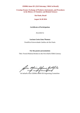
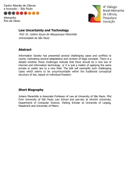
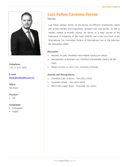
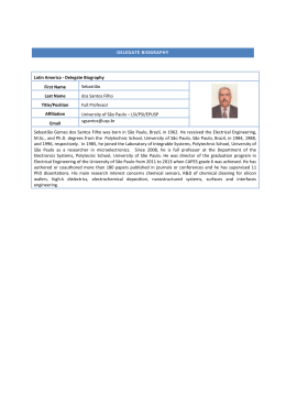
Artigo Original
Revista Brasileira de Física Médica. 2011;5(2):205-8.
Comparative study of two methodologies for
structural shielding design of imaging facilities
Estudo comparativo de dois métodos para o cálculo
estrutural de barreiras em instalações radiológicas
Lana T. Taniguti1 and Paulo R. Costa2
1
Bioscience Institute - Physics and Biophysics Department, State University of São Paulo – Botucatu (SP), Brazil.
2
Physics Institute - Nuclear Physics Department, University of São Paulo – São Paulo (SP), Brazil.
Abstract
The present study aimed at showing which implications can be found in structural radiation shielding design, depending on the calculation method
adopted. Two methods were analyzed: one that considers the sum of thickness contributions, and other that considers the sum of unshielded air
kerma contributions. To compare the results, a case analysis was done. A hypothetical radiographic room, which contains a table of exam and a chest
bucky, was considered. The thickness contribution method presented the highest results, reaching a maximum relative difference of 85% from the
results of the 147 National Council of Radiation Protection and Measurements, and 57% from the unshielded air kerma contributions method.
Keywords: shielding against radiation; radiation protection; air kerma; radiology.
Resumo
O presente estudo teve como objetivo mostrar quais implicações podem ser encontradas no cálculo estrutural de barreiras, dependendo do método
de cálculo utilizado. Dois métodos foram analisados: um que considera a soma das contribuições de espessura e outro que considera a soma das
contribuições de kerma no ar sem barreiras. Para comparação dos resultados, realizou-se uma análise de caso. Considerou-se uma sala radiográfica
hipotética, a qual continha uma mesa para exames e um bucky torácico. O método de contribuição de espessura apresentou os maiores resultados
alcançando uma diferença relativa máxima de 85% dos resultados do relatório 147 do National Council of Radiation Protection and Measurements,
e 57% do método das contribuições de kerma no ar sem barreiras.
Palavras-chave: barreiras contra radiação; proteção contra radiação; kerma no ar; radiologia.
Introduction
Materials and methods
In 1925, which was the year of the first International
Congress of Radiology, radiation protection practices began to be sketched, mainly, the need of shielding radiation
sources to prevent unnecessary exposure to patients and
workers1.
Recently, structural shielding design of radiological facilities intends to protect workers and individual members
of the public, decreasing the dose to restricted levels established by national regulations2,3.
Under this perspective, the National Council of Radiation
Protection and Measurements (NCRP) published a structural shielding design methodology in report 147, which
became a reference in the area4-7.
Therefore, this study aimed at comparing two methods
for calculating the final shielding thickness, using the 147
NCRP methodology.
Methodology of the NCRP 147
Equation 1 shows Archer’s formulation8 to calculate the
shielding thickness (x).
[ [
1
. ln
x=
F(W).L(W)
G(W)
F(W)
G(W)
1+
F(W)
BL(W) +
(1)
where:
α(W), β(W) and γ(W) are fitting parameters, which are
dependent of the attenuation properties of the considered
shielding material and also of the workload spectra (W).
Transmission factor (B) consists of the ratio of the
shielded air kerma (K(x)) by the unshielded air kerma (K(x=0)),
as shown in Eq. 24,8. The shielded air kerma is related
to the planned restriction of the area concerned, which
Corresponding author: Lana Tahara Taniguti – Physics Institute of State – University of São Paulo – Rua do Matão, Travessa R, 187 – São Paulo (SP), Brazil –
E-mail: [email protected]
Associação Brasileira de Física Médica®
205
Taniguti LT, Costa PR
means radiation restriction level (P) corrected by the occupancy factor (T).
B=
K(x)
K(x = 0)
=
P 1
.
T K(x = 0)
(2)
In addition, unshielded air kerma depends on equipment output (KW1), workload distribution (W), average number of patients examined in a week (N), and source’s distance (d), as indicated in Eq. 34,8.
Thickness contribution method
Figure 1 schematically shows the thickness contribution
method for a radiographic room.
This method uses Eq. 1 to calculate each shielding
thickness contribution, using specific workload distributions. For example, Figure 1A shows the use of the X-ray
tube for abdominal images, which utilizes a workload W1,
while Figure 1B shows its use for chest examinations,
whose workload is W2.
The final shielding thickness will be the sum of all thickness contributions for the analyzed barrier.
K 1 . W. N
K(x = 0) = w 2
d
(3)
In practice, for the equipment that is used with the
X-ray tube directed to more than one position, there are
two methods for calculating the required shielding thickness, especially for secondary barriers.
The first method consists initially on calculating the shielding thickness contribution using Eq. 1 for each X-ray tube position. Afterward, these individual thickness contributions are
summed in order to find the final shielding thickness.
The second method is operated by calculating the unshielded air kerma contribution, using Eq. 3 for each X-ray
tube position. The total unshielded air kerma is obtained
summing all individual unshielded air kerma contributions.
This value is used to find the transmission factor, which is
applied to calculate the final shielding thickness.
A
X-Ray tube position 1
Air kerma contribution method
Figure 2 schematically shows the air kerma contribution
method for a radiographic room.
This method uses Eq. 3 to calculate each unshielded air
kerma contribution. The sum of these contributions will be
used to calculate the transmission factor, B, to finally find the
shielding thickness necessary to protect the desired area.
Since α, β and γ are dependent on workload spectra, the
sum of all workload distributions, of each X-ray tube positioning, needs to be considered. The resulting values are summarized at the α, β and γ parameters for all barriers, which in
NCRP 147 is mentioned as RadRoom (all barriers)4.
Case study: radiographic room
A case analysis was done in order to compare both methods. The considered facility consisted on a radiographic
A
X-Ray tube position 1
x1(W1)
K(x=0)1
X-Ray tube position 2
X-Ray tube position 2
B
B
x2(W2)
x(W1 + W2) = x1(W1) + x2(W2)
K(x=0)2
C
Figure 1. Illustration of the thickness contribution method scheme.
206
Revista Brasileira de Física Médica. 2011;5(2):205-8.
K(x=0) = K(x=0)1 + K(x=0)2
C
Figure 2. Illustration of air kerma contribution method scheme.
Comparative study of two methodologies for structural shielding design of imaging facilities
room, which examines 125 patients per week, presented
as one of the examples at NCRP 147 (Example 5.34). This
hypothetical room was used to evaluate the result differences on the application of the two methods.
Figure 3 shows the X-ray tube positions, which were
considered to be used during the room routine, and
Figure 4 represents the case analyzed, showing the calculation parameters used.
A computer algorithm was developed9, and a computer
calculation software was used to execute the calculations.
Only secondary shielding thicknesses were calculated,
since primary barriers calculations for both methods result
in equal thickness values.
Results
Table 1 shows the shielding thickness results for the radiographic room presented in the Methodology, using the thickness and the air kerma contribution methods. Results of the
NCRP 1474 are also presented to compare the results.
Figures 5 and 6 indicate a comparative analysis of
the results, separated by lead and concrete thicknesses,
respectively.
Figure 3. The three X-ray tube positions considered to the case
analysis, indicating the respective use factors.
Discussion
Table 1 shows that all final shielding thickness, calculated
by the thickness contribution method, resulted in higher
values when compared to NCRP 147 results, which can
also be seen in Figures 5 and 6. This can be explained
by the fact that NCRP 147 calculation considers only one
X-ray tube position, although the radiographic room presents three ones.
Nevertheless, barriers A, E and F presented lower values compared to those presented in NCRP 147. This is
explained by the use of conservative distances by NCRP
147. In barrier A, for example, this publication used a distance of 3 m from the scatter radiation source (patient) to
the point to be protected, instead of 4.1 m presented by
the architectonical plant.
Therefore, the thickness contribution method also
showed the highest thicknesses needed for shielding the
room, when compared to unshielded air kerma contribution method. This fact demonstrates that calculating individual thicknesses, and summing all of them in the end
of the process represent a final shielding thickness higher
than calculated by others methods, such as the sum of
unshielded air kerma contributions.
For thickness contribution method applied to the studied radiographic room (Methodology), thicknesses differences reached 0.8 mm of lead and 28 mm of concrete
from NCRP 147 results. This corresponds to a relative
difference of 62 and 85%, respectively. The magnitude of
these differences is mainly due to the distances between
the secondary radiation sources from the interest point.
Figure 4. Illustration of the radiographic room used as an example for analyzing the two methods for structural shielding design.
Pink squares correspond to the barriers’ names.
Revista Brasileira de Física Médica. 2011;5(2):205-8.
207
Taniguti LT, Costa PR
Table 1. Results calculated by the thickness contribution method, and values presented by NCRP 1474.
Barrier
A
B
C
D
E
F
G
H
I
Ceiling
Wall around film box
Film Box
Floor around primary barrier
Wall around primary barrier
Wall around primary barrier
Wall
Door
Control wall
Thickness Contribution Method
48
0.7
2.1
61
0.4
1.1
0.7
0.6
0.4
Thickness (mm)
Unshielded Air Kerma Contribution Method
36
0.6
2.0
41
0.3
0.7
0.5
0.4
0.3
NCRP 147 results
44
0.5
1.3
33
0.4
1.0
0.3
Lead thickness [mm]
Conclusions
Thickness Contribution Method
Unshielded Air Kerma Contribution Method
NCRP 147
2.5
2
1.5
1
0.5
0
B
C
E
F
Barrier
G
H
I
Concrete thickness [mm]
Figure 5. Comparative plot of the lead thickness results of both
methods evaluated in this study, and the results presented at
NCRP 1474. Barriers G and H do not have NCRP 147 results because the publication do not present their shielding thicknesses.
70
60
50
40
30
20
10
0
Thickness Contribution
Method
Unshielded Air Kerma
Contribution Method
NCRP 147
A
Barrier
D
Figure 6. Comparative plot of the concrete thickness results of
both methods evaluated in this study, and results presented at
NCRP 1474.
As shorter as this distance is, more evidenced is the resulting thickness difference. This occurs because other
contributions of X-ray tube positions were not considered
by NCRP 147.
Also, from Table 1, unshielded air kerma contribution
method showed, in general, higher results when compared
to NCRP 147 values. This fact can also be explained by
the previous argument. However, these differences are
lower than those presented by the thickness contribution
method. This is due to the use of the summed workload
distribution RadRoom (all barriers) by NCRP 147.
208
Revista Brasileira de Física Médica. 2011;5(2):205-8.
The present study demonstrated the existence of differences in the final shielding thickness, depending on the
calculation method adopted. The results show that the
sum of the unshielded air kerma contribution method
presented optimized results compared to the sum of the
thickness contribution method.
Thickness differences between both methods reached
0.4 mm of lead and 20 mm of concrete for the considered
radiographic room (Methodology). These can be relevant
at final architectonical and engineering design of a radiological facility.
Acknowledgments
This study was supported by the National Council for
Scientific and Technological Development (CNPq), in
Brazil.
References
1. Archer BR. History of Shielding of Diagnostic X-ray Facilities. Health Physics.
1995;69(5):750-8.
2. Archer BR. Recent History of the Shielding of Medical X-Ray Imaging
Facilities. Health Physics. 2005;88(6):579-86.
3. Costa PR. Modelo para determinação de espessuras de barreiras protetoras
em salas para radiologia diagnóstica. [Thesis]. São Paulo: Energetic and
Nuclear Researches Institute of State University of São Paulo; 1999.
4. National Council on Radiation Protection and Measurements. Structural
Shielding Design for Medical X-Ray Imaging Facilities. Report nº 147.
Bethesda: NCRP Publications; 2004.
5. Turner JE. Front Matter, in Atoms, radiation and radiation protection.
Germany: Wiley-VCH; 2007.
6. Stabin MG. Radiation protection and dosimetry: an introduction to health
physics. New York: Springer; 2007;
7. Cember H, Johnson TE. Introduction to Health Physics. Fourth Edition.
McGraw-Hill; 2008.
8. Archer BR, Thomby JI, Bushong SC. Diagnostic X-ray shielding design
based on an empirical model of photon attenuation. Health Physics.
2008;44:507-17.
9. Taniguti LT. Cálculo Estrutural de Barreiras: desenvolvimento de um
algoritmo computacional de interface online. [dissertation]. Botucatu:
Bioscience Institute of State University of São Paulo; 2010.
Download