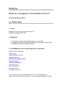
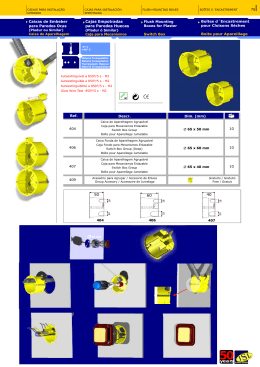
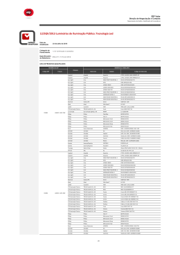
Geschraubte
Plattenwärmetauscher
Gasketed Plate Heat Exchanger
Echangeurs de chaleur à plaques et
joints démontables
1. ALLGEMEIN
Wärmetauscher dienen zur
Wärmeübertragung zwischen zwei
Medien.
Geschraubte Plattenwärmetauscher
sind Bauteile mit hoher Leistungsdichte
und bieten eine hohe Effizienz bei
kompakten Abmaßen. Darüber hinaus
zeichnen sie sich durch eine hohe
Flexibilität aus.
Diese Baureihe bildet zu der gelöteten
Ausführung eine sinnvolle Ergänzung
für höhere Leistungsbereiche und
Applikationen mit Seewasser.
1. GENERAL
Heat exchangers are used to transfer heat
between two media.
Gasketed plate heat exchangers are high
performance components and provide
a high level of efficiency combined with
compact dimensions. They also have a
high degree of flexibility.
For higher capacity ranges and marine
applications, this series is a useful
supplement to the brazed version.
Les échangeurs de chaleur sont destinés
à la transmission de chaleur entre deux
fluides.
Les échangeurs de chaleur à plaques et
joints démontables sont des composants
à haut degré d’étanchéité et offrent une
efficacité élevée pour un encombrement
réduit. Ils se caractérisent également par
une grande flexibilité.
En plus de l’exécution brasée, cette série
constitue un complément idéal pour des
plages de puissance plus élevées et des
applications avec de l'eau de mer.
DEF 5.809.1/11.09
1. GENERALITES
1.1 PRODUKTMERKMALE
Die geschraubten Plattenwärmetauscher
bestehen aus einem Paket einzelner,
geprägter Wärmeübertragungsplatten,
Plattenmaterial Edelstahl 1.4401
(AISI 316), 1.4306 (AISI 304) und Titan.
Die Abdichtung der Platten sowie die
Trennung der Medien erfolgt über
Dichtungen, Dichtungswerkstoff NitrilKautschuk (NBR), wahlweise FluorKautschuk (Viton) oder EPDM.
Der Einbau des Plattenpaketes erfolgt in
einem Gestell, das aus einer Fest- und
einer Druckplatte, Spannschrauben und
Stützen besteht.
Zur Abdeckung des Leistungsbereiches
stehen verschiedene Baugrößen mit
unterschiedlichen Plattenzahlen zur
Verfügung.
Der Rohrleitungsanschluss erfolgt über
Gewinde- oder Flanschanschlüsse.
Je nach Einsatzfall stehen
Sonderausführungen mit höherwertigen
Materialien (Titan) zur Verfügung. Für
diese Anwendungsfälle wenden Sie sich
bitte an die zuständige Fachabteilung.
Ebenso ist die Ausführung von
Sicherheits-Plattenwärmetauschern
möglich. Bei dieser Bauform werden
Leckagen sofort sichtbar und es kommt
in keinem Fall zu einer Vermischung der
Medien.
1.2 ANWENDUNGSBEREICH
DEF 5.809.1/11.09
Kühlkreisläufe im Gegenstrom
die mit Wasser, Kühlflüssigkeit,
HFC-Druckflüssigkeiten oder Ölen
betrieben werden. Für Anwendungen
mit anderen Medien bitte auch hier
die Fachabteilung kontaktieren.
Typische Anwendungen sind:
lHydrauliksysteme
lPressen
lSchmiersysteme
lPrüfstände
lMotoren
2
1.1 FEATURES
The gasketed plate heat exchanger consists
of a pack of individual, embossed heat
transfer plates made of stainless steel 1.4401
(AISI 316), 1.4306 (AISI 304) and titanium.
The plates are sealed and the media kept
separate by using gaskets in nitrile rubber
(NBR) or optionally FKM (Viton) or EPDM.
The plate pack is installed in a frame which
consists of a fixed plate and a pressure plate,
tightening bolts and supports. There are
several sizes with different numbers of plates
available to cover the capacity range.
The heat exchanger is connected inline via
threaded or flange connections.
Depending on the application, special models
are available with higher grade materials
(Titanium). For such applications, please
contact the relevant department.
Safety heat exchangers are also available.
This design ensures that any leakage is
visible immediately and mixing of the fluids is
completely prevented.
1.2 APPLICATIONS
For cooling circuits in reverse flow which
can be operated using water, coolants,
HFC operating fluids or oils.
For applications using other media, please
contact the relevant department.
Typical applications are:
lHydraulic systems
lPresses
lLubrication systems
lTest rigs
lEngines
1.1 CARACTERISTIQUES DU
PRODUIT
Les échangeurs de chaleur à plaques et
joints démontables sont composés d’un
pack de plaques de transfert de chaleur
individuelles nervurées, matériau des
plaques acier inox 1.4401 (AISI 316),
1.4306 (AISI 304) et titane.
La séparation des plaques et des fluides
est effectuée à l’aide de joints,
matériau des joints: nitrile-caoutchouc
(NBR), sur demande fluor-caoutchouc
(Viton) ou EPDM.
Le montage du paquet de plaques
s’effectue au moyen d’un châssis constitué
d’un bâti fixe et d’un bâti de compression
mobile, de vis de tension et de supports.
Des raccordements taraudés ou à bride
sont disponibles pour l’implantation de ces
échangeurs.
Selon le cas d’utilisation, des exécutions
spéciales avec des matériaux haut de
gamme (Titane) sont disponibles. Pour
ces cas d’application, nous vous prions
de vous adresser au service technique
compétent.
De même, une exécution d'échangeurs
à plaques de sécurité est possible. Cette
construction permet la détection immédiate
de fuites et évite le mélange des fluides.
1.2 DOMAINES D’UTILISATION
Circuits de refroidissement à contrecourant pour de l’eau, fluides de
refroidissement, fluides HFC , fluides
sous pression ou huiles. Veuillez
prendre contact avec notre service
technique pour une application avec
d’autres fluides.
Les applications typiques sont:
lSystèmes hydrauliques
lPresses
lSystèmes de lubrification
lBancs d’essai
lMoteurs
2.TYPENSCHLÜSSEL / MODEL CODE / CODE DE COMMANDE
H-38 - IG 10 - 12 - TKTM 33 - LIQUID
Baugröße
Size
Taille
Industriegestell
Industrial stand
Bâti industriel
Druckstufe
Pressure range
Pression de service
Plattenzahl
Number of plates
Nombre de plaques
Plattenform
Plate type
Type de plaques
Thermische Länge
Thermal length
Longueur thermique
Flüssigkeit
Fluid
Fluide
Medium:
lWasser-Glykol (Kühlflüssigkeit)
lHFC-Druckflüssigkeit
lWasser
lÖle
3. OPERATING DETAILS
Fluids:
lWater glycol (coolants)
lHFC operating fluids
lWater
lOil
Betriebstemperatur:
max. 140 °C
Operating temperature:
max. 140 °C
Druckstufen:
max. 10 bar, 16 bar, 25 bar
Pressure ranges:
max. 10 bar, 16 bar, 25 bar
Anmerkung:
Belastungen des Wärmetauschers
durch Druckspitzen sind zu
vermeiden.
Note:
Pressure surges must be avoided.
Wasserqualität:
Siehe Tabelle auf der nächsten Seite
Verschmutzung:
Der Gehalt an suspendierten
Feststoffen sollte unter 10 mg/l
liegen.
Partikelgröße < 0,6 mm (kugelförmig)
Fadenförmige Feststoffe führen
schnell zur Erhöhung der
Druckverluste.
Water quality:
See table on next page
Contamination:
The quantity of particles in suspension
should be less than 10 mg/l.
Particle size < 0.6 mm (spherical)
Thread-like particles cause a rapid rise
in pressure drops.
3. CARACTERISTIQUES DE
FONCTIONNEMENT
Fluide:
lMélange eau/glycol (liquide de
refroidissement)
lFluide hydraulique de type HFC
lEau
lHuile
Température de service:
max. 140 °C
Pression de service:
max. 10 bar, 16 bar, 25 bar
Remarques:
Les pics de pression sont à éviter.
Qualité de l'eau:
Voir tableau page suivante
Pollution:
La teneur en particules solides en
suspension doit être inférieure à 10 mg/l.
Taille des particules < 0,6 mm (forme
sphérique)
Les particules solides filiformes
contribuent à une augmentation rapide
de la perte de charge.
DEF 5.809.1/11.09
3. BETRIEBSDATEN
3
Wasser-Inhaltsstoffe
Substances dissolved in water
Composantes contenues dans l'eau
Aluminium (Al) – gelöst
Aluminium (Al) – in solution
Aluminium (Al) – dissout
Ammoniak (NH3)
Ammonia (NH3)
Ammoniac (NH3)
Chloride (Cl)- (max. 60 °C)
Chlorides (Cl)- (max. 60 °C)
Chlorure (Cl)- (max. 60 °C)
Elektr. Leitfähigkeit
Elect. conductivity
Conductibilité élec.
Eisen (Fe) – gelöst
Iron (Fe) – in solution
Fer (Fe) – dissout
Freie aggressive Kohlensäure (CO2)
Free agressive carbonic acid (CO2)
Dioxyde de carbone agressif libre (CO2)
Gesamthärte
Total hardness
Dureté totale
Glykolanteil
Glycol percentage
Taux de glycol
HCO3- SO4-2
HCO3- SO4-2
HCO3- SO4-2
Hydrogenkarbonat HCO3Hydrogen carbonate HCO3Bicarbonate HCO3Mangan (Mn) – gelöst
Manganese (Mn) – in solution
Manganèse (Mn) – dissout
Nitrate – gelöst NO3
Nitrates – in solution NO3
Nitrate – dissout NO3
pH-Wert
pH value
PH
Sulfate SO42Sulphates SO42Sulfate SO42Sulfit SO3 / Freies Chlorgas Cl2
Sulphite SO3 / free chlorine gas Cl2
Sulfite SO3 / gaz de chlore Cl2
Schwefelwasserstoff H2S
Hydrogen sulphide H2S
Sulfure d'hydrogène H2S
DEF 5.809.1/11.09
A =unter normalen Umständen gute
Beständigkeit
B =korrosionsgefährdet, besonders
wenn mehrere Stoffe mit B
vorliegen
C =nicht geeignet
4
Chloridgehalt
Chloride content
Teneur en chlorure
≤ 10 ppm
≤ 25 ppm
≤ 50 ppm
≤ 80 ppm
≤ 150 ppm
≤ 300 ppm
> 300 ppm
Hinweis: Diese Tabelle ist nicht
vollständig und dient lediglich der
Orientierung (ohne Gewähr).
Konzentration der Inhaltsstoffe in mg/l
Concentration of substance in mg/l
Concentration des composantes
contenues dans l'eau mg/l
Hinweise zu 1.4401
Notes below relate to 1.4401
Remarques concernant 1.4401
< 0,2
> 0,2
A
A
<2
2 – 20
> 20
A
A
A
< 250
> 250
A
B
< 10 μ S/cm
10 – 500 μ S/cm
> 500 μ S/cm
A
A
A
< 0,2
> 0,2
A
A
<5
5 – 20
> 20
A
A
A
4,0 – 8,5 °dH
A
< 20%
20 – 50%
> 50%
A
A
A
< 1,0
> 1,0
A
A
< 70
70 – 300
> 300
A
A
A
< 0,1
> 0,1
A
A
< 100
> 100
A
A
<6
6.0 – 7,5
7,5 – 9,0
>9
< 70
70 – 300
> 300
<1
1–5
>5
B
A/B
A
A
A
A
C
A
A
A/B
< 0,05
> 0,05
A
A
A =under normal conditions, good
resistance
B =prone to corrosion, especially if
several B substances are present
C =not suitable
A =bonne compatibilité dans des
conditions normales
B =danger de corrosion
particulièrement si plusieurs
matières sont présentes avec B
C =ne convient pas
max. Wandflächentemperatur /
max. wall surface temperature / Température max. de la paroi
60 °C
80 °C
120 °C
W 1.4301
W 1.4301
W 1.4301
W 1.4301
W 1.4301
W 1.4401
W 1.4301
W 1.4401
W 1.4401
W 1.4401
W 1.4401
W 1.4401
W 1.4401
W 1.4401
Ti
W 1.4401
Ti
Ti
Ti
Ti
Ti
Note: This table is not exhaustive
and serves only as an indication
(no guarantee).
130 °C
W 1.4401
W 1.4401
Ti
Ti
Ti
Ti
Ti
Attention: Ce tableau n'est pas exhaustif
et ne sert que de manière indicative
(sans garantie).
4.2 ABMESSUNGEN/ DIMENSIONS/ ENCOMBREMENTS
BEFESTIGUNG/ MOUNTING / FIXATION
H2
Befestigung
Mounting
Fixation
Rahmen
Frame
Bâti
Druckstufen: 10 bar
Pressure ranges: 10 bar
Pression de service: 10 bar
Baugröße
Size
Taille
H2
Abmessung H
Dimension H
Dimension H
mm
272
Abmessung C
Dimension C
Dimension C
mm
175
H8 / H16
Baugröße
Size
Taille
Rahmen
Frame
Bâti
H8
H16
Abmessung H
Dimension H
Dimension H
mm
473
748
Abmessung C
Dimension C
Dimension C
mm
381
656
DEF 5.809.1/11.09
Druckstufen: 16 bar
Pressure ranges: 16 bar
Pression de service: 16 bar
5
H8 / H16
Befestigung
Mounting
Fixation
Druckstufen: 16 bar, 25 bar
Pressure ranges: 16 bar, 25 bar
Pression de service: 16 bar, 25 bar
Baugröße
Size
Taille
Rahmen
Frame
Bâti
H14 / H28 / H40
H8
H16
Abmessung H
Dimension H
Dimension H
mm
621
896
Abmessung C
Dimension C
Dimension C
mm
381
656
Rahmen 25 bar
Frame 25 bar
Bâti 25 bar
Rahmen 16 bar
Frame 16 bar
Bâti 16 bar
Druckstufen: 16 bar, 25 bar
Pressure ranges: 16 bar, 25 bar
Pression de service: 16 bar, 25 bar
DEF 5.809.1/11.09
Baugröße
Size
Taille
6
Befestigung
Mounting
Fixation
H14
H28
H40
Abmessung H
Dimension H
Dimension H
mm
694
994
1194
Abmessung C
Dimension C
Dimension C
mm
394
694
894
H18 / H38 / H62
Rahmen 16 bar
Frame 16 bar
Bâti 16 bar
Rahmen 10 bar
Frame 10 bar
Bâti 10 bar
Druckstufen: 10 bar, 16 bar
Pressure ranges: 10 bar, 16 bar
Pression de service: 10 bar, 16 bar
Baugröße
Size
Taille
Befestigung
Mounting
Fixation
H18
H38
H62
Abmessung H
Dimension H
Dimension H
mm
626
946
1296
Abmessung C
Dimension C
Dimension C
mm
380
700
1050
H42 / h44 / h94 / h128
L = 400 - 1000 mm
Befestigung
Mounting
Fixation
Rahmen
Frame
Bâti
Baugröße
Size
Taille
H42 / H44
H94
H128
Abmessung H
Dimension H
Dimension H
mm
1069
1715
2121
Abmessung C
Dimension C
Dimension C
mm
719
1365
1771
DEF 5.809.1/11.09
Druckstufen: 10 bar
Pressure ranges: 10 bar
Pression de service: 10 bar
7
H42 / h44 / h94 / h128
L = 600 - 2000 mm
Befestigung
Mounting
Fixation
Druckstufen: 10 bar, 16 bar, 25 bar
Pressure ranges: 10 bar, 16 bar, 25 bar
Pression de service: 10 bar, 16 bar, 25 bar
Baugröße
Size
Taille
Rahmen
Frame
Bâti
H42 / H44
H94
H128
Abmessung H
Dimension H
Dimension H
mm
1108
1755
2162
Abmessung C
Dimension C
Dimension C
mm
719
1365
1771
Abmessung B
Dimension B
Dimension B
mm
495
480
480
H42 / h44 / h94 / h128
L = 2500 - 4000 mm
Befestigung
Mounting
Fixation
DEF 5.809.1/11.09
Druckstufen: 10 bar, 16 bar, 25 bar
Pressure ranges: 10 bar, 16 bar, 25 bar
Pression de service: 10 bar, 16 bar, 25 bar
8
Rahmen
Frame
Bâti
Baugröße
Size
Taille
H42 / H44
H94
H128
Abmessung H
Dimension H
Dimension H
mm
1238
1884
2291
Abmessung C
Dimension C
Dimension C
mm
719
1365
1771
Abmessung B
Dimension B
Dimension B
mm
495
480
480
H74 / h102
Befestigung
Mounting
Fixation
Druckstufen: 10 bar, 16 bar
Pressure ranges: 10 bar, 16 bar
Pression de service: 10 bar, 16 bar
Baugröße
Size
Taille
Rahmen
Frame
Bâti
H74
H102
Abmessung H
Dimension H
Dimension H
mm
1441
1855
Abmessung C
Dimension C
Dimension C
mm
1070
1484
H82 / H84 / H124 / H172 / H220
Befestigung
Mounting
Fixation
Rahmen
Frame
Bâti
Baugröße
Size
Taille
H82 / H84
H124
H172
H220
Abmessung H Abmessung C Abmessung B
Dimension H
Dimension C
Dimension B
Dimension H
Dimension C
Dimension B
10 bar, 16 bar
mm
mm
mm
1450
890
608
1852
1292
608
2254
1694
608
2654
2094
608
Abmessung B
Dimension B
Dimension B
25 bar
mm
640
640
640
640
DEF 5.809.1/11.09
Druckstufen: 10 bar, 16 bar, 25 bar
Pressure ranges: 10 bar, 16 bar, 25 bar
Pression de service: 10 bar, 16 bar, 25 bar
9
5. ANMERKUNG
DEF 5.809.1/11.09
Die Auslegung eines geschraubten
Plattenwärmetauschers ist von
verschiedenen Parametern abhängig.
In jedem Fall wird eine individuelle
Auslegung empfohlen. Hierzu ist die
Angabe der auslegungsrelevanten
Daten notwendig. Eine Hilfe bietet das
Auslegungsblatt auf Seite 11.
Die Angaben in diesem Prospekt
beziehen sich auf die beschriebenen
Betriebsbedingungen und
Einsatzfälle.
Bei abweichenden Einsatzfällen und/
oder Betriebsbedingungen wenden
Sie sich bitte an die entsprechende
Fachabteilung.
Technische Änderungen sind
vorbehalten.
10
5. NOTE
Sizing a gasketed plate heat exchanger
depends on various parameters.
An individual calculation is always
recommended. Certain details are
required to make such a calculation. The
calculation sheet included on page 11
should help in this process.
The information in this brochure
relates to the operating conditions and
applications described.
For applications or operating conditions
not described, please contact the
relevant technical department.
Subject to technical modifications.
5. REMARQUE
La détermination d’un échangeur de
chaleur à plaques et joints démontables
dépend de différents paramètres.
Nous recommandons, dans tous les
cas, une détermination individuelle. A
cet effet, il est nécessaire d’indiquer
les informations essentielles à la
détermination. Le formulaire de
détermination en page 11 fournit une
aide à ce sujet.
Les données de ce prospectus
se réfèrent aux conditions de
fonctionnement et d’utilisation décrites.
Pour des conditions de fonctionnement
et d’utilisation différentes, veuillez
vous adresser au service technique
compétent.
Sous réserve de modifications
techniques.
6. Auslegungsblatt / Calculation sheet / Fiche Determination
Kunde /
Customer /
client
Projekt-Nr. /
Project no. /
no. du projet
Straße /
Address /
rue
Name /
Name /
nom
Postfach /
Post code /
boîte postale
Liefertermin /
Date of delivery /
date de livraison
Ort /
Country /
localité
Datum /
Date /
date
Tel.-Nr.
e-mail
1.0 Verwendung /
Application /
application
2.0 Auslegungsdaten / Sizing data / informations techniques
Maßeinheit
Unit of
measurement
Unité de
mesure
Warme
Seite
Hot side
Côté
chaud
Kalte
Seite
Cold side
Côté froid
2.1 Leistung / heat to be dissipated / puissance
2.2 Medium / fluid / fluide
2.3 Aggregatzustand / medium state (fluid / gas) / état de la matière
2.4 Durchflussmenge / flow rate / débit
2.5 Eintrittstemtemperatur / inlet temperature / température d’entrée
2.6 Austrittstemperatur / outlet temperature / température de sortie*
2.7 Zul. Druckverlust / permissible pressure drop / perte de charge admissible
2.8 Dichte / density / densité
2.9 Spez. Wärmekapazität / specific heat capacity / chaleur spécifique
2.10 Wärmeleitfähigkeit / thermal conductivity / conductibilité thermique
2.11 Viskosität / viscosity / viscosité
2.12 Betriebsüberdruck / operating pressure / surpression de service
2.13 Auslegungsdruck / design pressure / pression de calcul
2.14 Probeüberdruck / test pressure / surpression d’épreuve
2.15 Auslegungstemperatur / design temperature / température de calcul
3.0 Ausführung / Design / construction
3.1 Bauart / type of construction / type de construction
3.2 Werkstoff / material / matière
Platten / plates / plaques
Dichtungen / gaskets / joints
4. Sonstiges / Miscellaneous / autres
* Provided the heat be dissipated is
given, the outlet temperature can be
calculated, i.e. it is not necessary to give
the outlet temperature
* En cas d’indication de la puissance,
les températures de sortie résultent du
calcul, c’est à dire qu’aucune indication
de cette température n’est nécessaire.
Cooling GmbH
Industriegebiet
D-66280 Sulzbach/Saar
Tel.: 0 68 97 / 509-01
Telefax: 0 68 97 / 509-454
Internet: www.hydac.com
E-Mail: [email protected]
DEF 5.809.1/11.09
* Bei Angabe der Leistung ergeben
sich die Austrittstemperaturen
aus der Berechnung, d.h. keine
Temperaturangaben erforderlich.
11
Download